7
13. Reinstall the coupling (43) on the pump and motor
shaft. If the pump has a shaft pin, the pin axially
locates the pump shaft. If the pump does not have a
shaft pin, then set the coupling so that it grips equal
lengths of the pump and motor shaft.
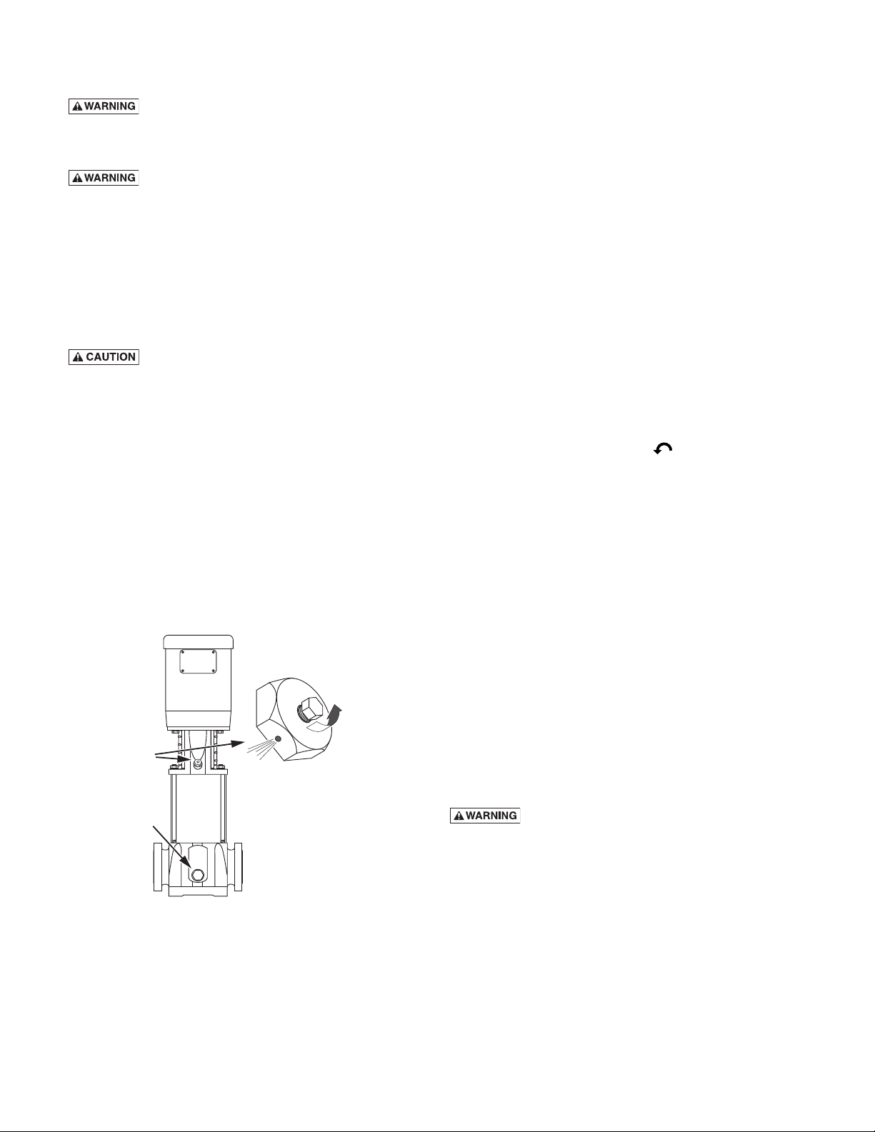
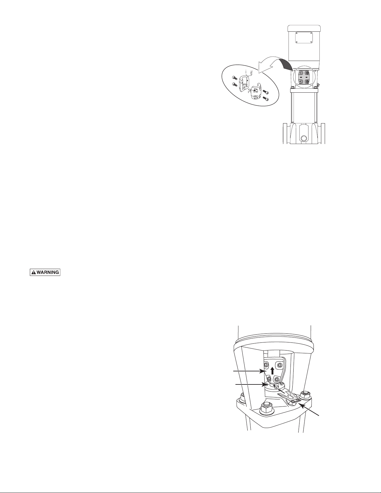
14. Tighten the coupling’s socket head cap screws (73).
NOTICE: Torque settings are critical to prevent
coupling movement. If the coupling is not tightened
to the correct torque, it could slip on the shaft and
overheat and damage both the coupling and the
shaft. Refer to Table III, for torque specifications. Be
sure to tighten the two halves of the coupling evenly
(seeFigure8).
15. Remove the stack height adjustment tool and clip it
to one of the coupling guards.
16. Rotate the shaft to make sure that there is no
interference. After assembly there should be a small
gap between the shaft collar and the bracket. If
anything rubs, repeat steps 13, 14, and 15 to readjust
pump shaft height.
17. Reinstall the coupling guards.
NOTICE: The guards should be in place before the
unit is run.
18. Openthesuctionanddischargevalves.Turnthe
power back on.
Replacing Mechanical Seal
1. FollowSteps1-7underMotorReplacementandthen
proceed with Step 2 below.
2. Loosen the three set screws in the shaft collar above
the mechanical seal and remove the shaft collar.
3. Remove the four retaining bolts (69) that hold down
the seal flange and seal.
4. Use a flat screwdriver to pry up the seal flange.
Remove the top portion of the seal.
5. Using the three round holes on the top of the shaft
sleeve,ornotchinflange(seeFigure9),removethe
remaining portions of the seal.
6. Clean the seal seat area with a wetted cloth.
NOTICE: Be sure that you do not scratch, chip, or
scar the seal face. Be sure that the seal face is clean
before finishing assembly.
7. Wipe a small amount of water onto the O-Ring on
the inside of the new seal.
8. Slidethenewsealassemblyontotheshaftasasingle
unit.
9. Install the four retaining bolts in the seal flange and
tighten them to 3.0 foot-lbs. (4.0 Nm).
10. FollowSteps8through19underMotorReplacement
to reinstall the motor.
Replacing Pump Stack
Thereferencenumbers[shownas(11)or(88)]refer
totheexplodedviews,Figures10-13.Seethe
appropriate exploded view for your model series.
1. Followsteps1-7underMotorReplacement,then
proceed with step 2 below.
2. Remove the motor bracket adapter plate (50), if your
pump has one.
3. Followsteps2-5underMechanicalSeal
Replacement and then proceed with Step 3 below.
4. Removethestayboltnuts(77)andflatwashers(78)
fromthestaybolts(81).Usevicegrips,ifnecessary,
to prevent the staybolts from unscrewing out of the
pump base.
NOTICE: It is not necessary to remove the staybolts
when replacing the stack.
5. With the base firmly attached to a solid floor,
pull the motor stool (36) or motor stool/pump
head assembly (36/53 or 36/56) straight up off the
staybolts.
6. Make a note of the orientation of any tabs in the
top of the stack assembly, then remove the stack
assembly by pulling it straight up.
7. Install the new stack assembly, making sure that the
orientation of the tabs matches the orientation of the
tabs on the old stack assembly.
8. ReplacethestacksleeveO-Ring(82)locatedinthe
motor stool (36/53) or pump head (36/56). Make sure
that the new O-Ring is evenly seated in the O-Ring
groove in the motor stool or pump head.
9. Apply water to the stack sleeve O-Ring in the motor
stool/pumphead(82)andtothetopofthestack
sleeve(48).
Figure 8 - Make Sure that the coupling halves are evenly
tightened
Shaft Sleeve
Flange
Head
Figure 9