Pentax EPK-700 User manual

EPK-700
VIDEO PROCESSOR
OWNER‘S MANUAL

INTENDED USE:
This electro-medical device (Video Processor) is intended to be used for endoscopic diagnosis and treatment.
Together, this Video Processor and Pentax video endoscope provide optical visualization of, and/or therapeutic access to, various bod cavities,
organs and canals. Do not use this device for an purpose other than that for which it has been designed.
This device should onl be used b ph sicians who have thoroughl studied all the characteristics of this device and who are familiar with the
proper techniques of endoscop .
IMPORTANT
Read this manual before operating and keep this book for future reference.
This manual describes the recommended procedures for inspecting and preparing the EPK-700 Video Processor prior to its use and the care and
maintenance after its use. It does not describe how an actual procedure is to be performed, nor does it attempt to teach the beginner the proper
technique or an medical aspects regarding the use of the equipment. Failure to follow the instructions in this manual ma result in damage to
and/or malfunction of the equipment.
Do not use this device for an other purpose than that for which it has been designed.
If ou have an questions regarding an of the information in this manual or concerns pertaining to the safet and/or use of this equipment,
please contact our local Pentax representative.
CAUTION:
Federal (USA) law restricts this device to sale b , or on the order of a ph sician or other appropriatel licensed medical professional.
The CE mark guarantees that this product complies with the EU directive for safety requirements.
Das CE Zeichen garantiert, daß dieses Produkt die in der EU erforderlichen Sicherheitsbestimmungen erfüllt.
Le logo CE certifie que ce produit est conforme aux normes de sécurité prévues par la Communauté Européenne.
Il marchio Ce assicura che questo prodotto è conforme alle direttive CE relative alla sicurezza.
La marca CE asegura que este producto cumple todas las directivas de seguridad de la CE.
A marca CE garante que este produto cumpre todas as normas de segurança previstas pela Comunidade Europeia
CE-märkningen garanterar att denna produkt uppfyller EU-direktivens krav på säkerhet.
Het CE-teken garandeert dat dit product voldoet aan de binnen de EU vereiste veiligheidsbepalingen.
CE-merkintä on takeena siitä, että tämä tuote vastaa EU:ssa voimassa olevia ja direktiivin tarkoittamia turvallisu-
usmääräyksiä.
Το σήµα CE εγγυάται τι το προϊν αυτ πληροί τους κανονισµούς ασφαλείας που απαιτούνται στην ΕΕ.

CONTENTS
3
CONTENTS
1
Safety precautions. . . . . . . . . . . . . . . . . . . . . . . . . . . . . . . . . . . . . . . . . . . . . . . . . . . . . . . . . . . . . . . . . . . . . . . . . . . . . . . . . 05
2
Specifications . . . . . . . . . . . . . . . . . . . . . . . . . . . . . . . . . . . . . . . . . . . . . . . . . . . . . . . . . . . . . . . . . . . . . . . . . . . . . . . . . . . . 08
3
Nomenclature, controls and functions. . . . . . . . . . . . . . . . . . . . . . . . . . . . . . . . . . . . . . . . . . . . . . . . . . . . . . . . . . . . . . . . . . 09
3-1 EPK-700 video processor. . . . . . . . . . . . . . . . . . . . . . . . . . . . . . . . . . . . . . . . . . . . . . . . . . . . . . . . . . . . . . . . . . . . . . . . 09
1 Main body . . . . . . . . . . . . . . . . . . . . . . . . . . . . . . . . . . . . . . . . . . . . . . . . . . . . . . . . . . . . . . . . . . . . . . . . . . . . . . . . 09
2 Front panel . . . . . . . . . . . . . . . . . . . . . . . . . . . . . . . . . . . . . . . . . . . . . . . . . . . . . . . . . . . . . . . . . . . . . . . . . . . . . . . . 10
3 Rear panel . . . . . . . . . . . . . . . . . . . . . . . . . . . . . . . . . . . . . . . . . . . . . . . . . . . . . . . . . . . . . . . . . . . . . . . . . . . . . . . . 11
3-2 Water bottle assembly, model OS-H2 . . . . . . . . . . . . . . . . . . . . . . . . . . . . . . . . . . . . . . . . . . . . . . . . . . . . . . . . . . . . . . 12
3-3 Keyboard. . . . . . . . . . . . . . . . . . . . . . . . . . . . . . . . . . . . . . . . . . . . . . . . . . . . . . . . . . . . . . . . . . . . . . . . . . . . . . . . . . . . . 13
3-4 Monitor display screen . . . . . . . . . . . . . . . . . . . . . . . . . . . . . . . . . . . . . . . . . . . . . . . . . . . . . . . . . . . . . . . . . . . . . . . . . . 14
1 Normal . . . . . . . . . . . . . . . . . . . . . . . . . . . . . . . . . . . . . . . . . . . . . . . . . . . . . . . . . . . . . . . . . . . . . . . . . . . . . . . . . . . 14
2 Freeze (sub-screen display) . . . . . . . . . . . . . . . . . . . . . . . . . . . . . . . . . . . . . . . . . . . . . . . . . . . . . . . . . . . . . . . . . . . 14
4
Preparation and safety check . . . . . . . . . . . . . . . . . . . . . . . . . . . . . . . . . . . . . . . . . . . . . . . . . . . . . . . . . . . . . . . . . . . . . . . . 15
4-1 Preparation . . . . . . . . . . . . . . . . . . . . . . . . . . . . . . . . . . . . . . . . . . . . . . . . . . . . . . . . . . . . . . . . . . . . . . . . . . . . . . . . . . . 15
1 Setting up the EPK-700 . . . . . . . . . . . . . . . . . . . . . . . . . . . . . . . . . . . . . . . . . . . . . . . . . . . . . . . . . . . . . . . . . . . . . . 15
2 Connecting the water bottle. . . . . . . . . . . . . . . . . . . . . . . . . . . . . . . . . . . . . . . . . . . . . . . . . . . . . . . . . . . . . . . . . . . 15
3 Connecting the endoscope . . . . . . . . . . . . . . . . . . . . . . . . . . . . . . . . . . . . . . . . . . . . . . . . . . . . . . . . . . . . . . . . . . . 16
4 Connecting the peripheral equipment . . . . . . . . . . . . . . . . . . . . . . . . . . . . . . . . . . . . . . . . . . . . . . . . . . . . . . . . . . . 17
4-2 Pre-use safety checklist . . . . . . . . . . . . . . . . . . . . . . . . . . . . . . . . . . . . . . . . . . . . . . . . . . . . . . . . . . . . . . . . . . . . . . . . . 17
5
Operation . . . . . . . . . . . . . . . . . . . . . . . . . . . . . . . . . . . . . . . . . . . . . . . . . . . . . . . . . . . . . . . . . . . . . . . . . . . . . . . . . . . . . . . . 20
5-1 Function key indexes . . . . . . . . . . . . . . . . . . . . . . . . . . . . . . . . . . . . . . . . . . . . . . . . . . . . . . . . . . . . . . . . . . . . . . . . . . . 20
5-2 Setting the date and clock . . . . . . . . . . . . . . . . . . . . . . . . . . . . . . . . . . . . . . . . . . . . . . . . . . . . . . . . . . . . . . . . . . . . . . . 20
5-3 Second adjustment. . . . . . . . . . . . . . . . . . . . . . . . . . . . . . . . . . . . . . . . . . . . . . . . . . . . . . . . . . . . . . . . . . . . . . . . . . . . . 21
5-4 Entering screen (patient) data. . . . . . . . . . . . . . . . . . . . . . . . . . . . . . . . . . . . . . . . . . . . . . . . . . . . . . . . . . . . . . . . . . . . . 21
1 Clearing screen information . . . . . . . . . . . . . . . . . . . . . . . . . . . . . . . . . . . . . . . . . . . . . . . . . . . . . . . . . . . . . . . . . . . 21
2 Entering screen information . . . . . . . . . . . . . . . . . . . . . . . . . . . . . . . . . . . . . . . . . . . . . . . . . . . . . . . . . . . . . . . . . . . 21
3 Editing/correcting screen information . . . . . . . . . . . . . . . . . . . . . . . . . . . . . . . . . . . . . . . . . . . . . . . . . . . . . . . . . . . 22
5-5 Processor functions . . . . . . . . . . . . . . . . . . . . . . . . . . . . . . . . . . . . . . . . . . . . . . . . . . . . . . . . . . . . . . . . . . . . . . . . . . . . 23
1 Lamp . . . . . . . . . . . . . . . . . . . . . . . . . . . . . . . . . . . . . . . . . . . . . . . . . . . . . . . . . . . . . . . . . . . . . . . . . . . . . . . . . . . . 23
2 Brightness . . . . . . . . . . . . . . . . . . . . . . . . . . . . . . . . . . . . . . . . . . . . . . . . . . . . . . . . . . . . . . . . . . . . . . . . . . . . . . . . 23
3 Colour balance. . . . . . . . . . . . . . . . . . . . . . . . . . . . . . . . . . . . . . . . . . . . . . . . . . . . . . . . . . . . . . . . . . . . . . . . . . . . . 25
4 XLUM (Transillumination) . . . . . . . . . . . . . . . . . . . . . . . . . . . . . . . . . . . . . . . . . . . . . . . . . . . . . . . . . . . . . . . . . . . . . 25
5 Air pump. . . . . . . . . . . . . . . . . . . . . . . . . . . . . . . . . . . . . . . . . . . . . . . . . . . . . . . . . . . . . . . . . . . . . . . . . . . . . . . . . . 25
6 Copy. . . . . . . . . . . . . . . . . . . . . . . . . . . . . . . . . . . . . . . . . . . . . . . . . . . . . . . . . . . . . . . . . . . . . . . . . . . . . . . . . . . . . 26
7 VCR . . . . . . . . . . . . . . . . . . . . . . . . . . . . . . . . . . . . . . . . . . . . . . . . . . . . . . . . . . . . . . . . . . . . . . . . . . . . . . . . . . . . . 26
8 Enhance . . . . . . . . . . . . . . . . . . . . . . . . . . . . . . . . . . . . . . . . . . . . . . . . . . . . . . . . . . . . . . . . . . . . . . . . . . . . . . . . . . 26
9 Colour bar . . . . . . . . . . . . . . . . . . . . . . . . . . . . . . . . . . . . . . . . . . . . . . . . . . . . . . . . . . . . . . . . . . . . . . . . . . . . . . . . 26
10 Screen characters on/off . . . . . . . . . . . . . . . . . . . . . . . . . . . . . . . . . . . . . . . . . . . . . . . . . . . . . . . . . . . . . . . . . . . . . 27
11 Pointer . . . . . . . . . . . . . . . . . . . . . . . . . . . . . . . . . . . . . . . . . . . . . . . . . . . . . . . . . . . . . . . . . . . . . . . . . . . . . . . . . . . 27
12 Freeze image control mode . . . . . . . . . . . . . . . . . . . . . . . . . . . . . . . . . . . . . . . . . . . . . . . . . . . . . . . . . . . . . . . . . . . 27
13 Stopwatch . . . . . . . . . . . . . . . . . . . . . . . . . . . . . . . . . . . . . . . . . . . . . . . . . . . . . . . . . . . . . . . . . . . . . . . . . . . . . . . . 27
14 Colour adjustment . . . . . . . . . . . . . . . . . . . . . . . . . . . . . . . . . . . . . . . . . . . . . . . . . . . . . . . . . . . . . . . . . . . . . . . . . . 28
15 Scope buttons . . . . . . . . . . . . . . . . . . . . . . . . . . . . . . . . . . . . . . . . . . . . . . . . . . . . . . . . . . . . . . . . . . . . . . . . . . . . . 28
16 Control of video processor function from the endoscope control bottons . . . . . . . . . . . . . . . . . . . . . . . . . . . . . . . 29
6
Maintenance . . . . . . . . . . . . . . . . . . . . . . . . . . . . . . . . . . . . . . . . . . . . . . . . . . . . . . . . . . . . . . . . . . . . . . . . . . . . . . . . . . . . . 30
6-1 After each procedure . . . . . . . . . . . . . . . . . . . . . . . . . . . . . . . . . . . . . . . . . . . . . . . . . . . . . . . . . . . . . . . . . . . . . . . . . . . 30
6-2 Water bottle cleaning . . . . . . . . . . . . . . . . . . . . . . . . . . . . . . . . . . . . . . . . . . . . . . . . . . . . . . . . . . . . . . . . . . . . . . . . . . . 30
1 Cleaning . . . . . . . . . . . . . . . . . . . . . . . . . . . . . . . . . . . . . . . . . . . . . . . . . . . . . . . . . . . . . . . . . . . . . . . . . . . . . . . . . . 30

CONTENTS
4
2 Sterilization . . . . . . . . . . . . . . . . . . . . . . . . . . . . . . . . . . . . . . . . . . . . . . . . . . . . . . . . . . . . . . . . . . . . . . . . . . . . . . . 31
2-1 Steam sterilization . . . . . . . . . . . . . . . . . . . . . . . . . . . . . . . . . . . . . . . . . . . . . . . . . . . . . . . . . . . . . . . . . . . . . . . . . . 31
2-2 ETO Sterilization . . . . . . . . . . . . . . . . . . . . . . . . . . . . . . . . . . . . . . . . . . . . . . . . . . . . . . . . . . . . . . . . . . . . . . . . . . . 32
3 Care during storage. . . . . . . . . . . . . . . . . . . . . . . . . . . . . . . . . . . . . . . . . . . . . . . . . . . . . . . . . . . . . . . . . . . . . . . . . 32
6-3 Storage. . . . . . . . . . . . . . . . . . . . . . . . . . . . . . . . . . . . . . . . . . . . . . . . . . . . . . . . . . . . . . . . . . . . . . . . . . . . . . . . . . . . . . 32
6-4 Changing the lamp . . . . . . . . . . . . . . . . . . . . . . . . . . . . . . . . . . . . . . . . . . . . . . . . . . . . . . . . . . . . . . . . . . . . . . . . . . . . . 32
6-5 Resetting the circuit breakers . . . . . . . . . . . . . . . . . . . . . . . . . . . . . . . . . . . . . . . . . . . . . . . . . . . . . . . . . . . . . . . . . . . . 33
7
Trouble-shooting guide. . . . . . . . . . . . . . . . . . . . . . . . . . . . . . . . . . . . . . . . . . . . . . . . . . . . . . . . . . . . . . . . . . . . . . . . . . . . . 34
8
Function summary diagram . . . . . . . . . . . . . . . . . . . . . . . . . . . . . . . . . . . . . . . . . . . . . . . . . . . . . . . . . . . . . . . . . . . . . . . . . 35

SAFETY PRECAUTIONS – IMPORTANT
5
1 Safety precautions –
important
The following precautions should alwa s be taken when using
electro-medical equipment to ensure safet to all parties involved
– user(s), patient(s), etc.
Please stud and compl with this owner’s manual.
1-1 Training
1. This equipment should onl be used under the supervision
of a trained ph sician in a medical facilit . Do not use in
other locations or for an other purposes than the intended
application.
1-2 Installation
1. This equipment should NEVER be installed or used in areas
where the unit could get wet or be exposed to an adverse
environmental conditions such as high temperature, humidit ,
direct sunlight, dust, salt, etc., which could adversel affect
the equipment.
2. This equipment should NEVER be installed or used in the
presence of flammable or explosive gases or chemicals.
3.
This equipment should NEVER be installed, used or transported
in an inclined position nor should it be subjected to impact or
vibration.
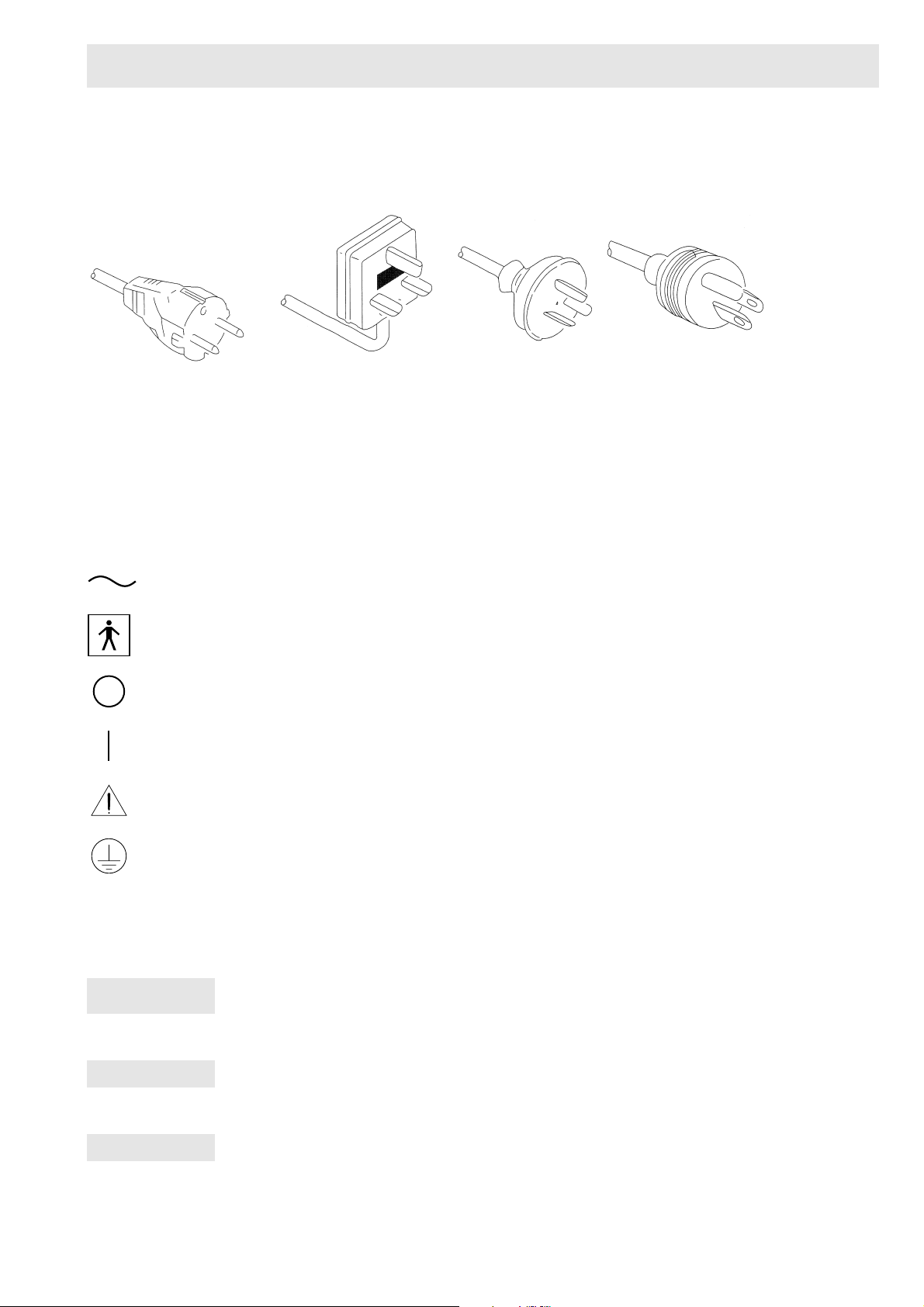
4. For safet reasons, this equipment must be properl grounded.
(This equipment should be connected to a three-pin hospital
grade socket outlet in U.S.A. or Canada.)
5. Ensure that all power requirements are met and conform to
those specified on the name plate located on the rear panel.
6. Do not block the air intake vent of this equipment.
7. Do not allow the power cord to become twisted, crushed or
pulled taut.
8. When using an isolating transformer for an ancillar
equipment, ensure the power requirements of the devices do
not exceed the capacit of the isolating transformer. For
further information, contact our local Pentax distributor.
1-3 Prior to use
1. Confirm that this equipment functions properl and check the
operation of all switches, indicators, etc.
2. To prevent electric shock when used with endoscopes, this
equipment is insulated (t pe BF electro-medical equipment).
Do not allow it to be grounded to other electrical devices being
used on the patient. Rubber gloves should alwa s be worn to
prevent grounding through user(s).
3. Confirm that other devices used in conjunction with this
equipment function properl and that these other devices will
not adversel affect the operation or safet of this equipment.
If an component of the endoscopic s stem is not functioning
properl , the procedure should not be performed.
4. Check and confirm that all cords and cables are connected
correctl and securel and are not damaged.
1-4 During use
1. To prevent electric shock, the endoscope and/or an other
ancillar device should NEVER be applied directl to the heart.
2. Make sure that no contact is made between the patient and this
equipment.
3. To avoid damage to the luminous displa and flat touch
switches, do not press an ke s with sharp or pointed objects.
4. The light emitted b the (Metal Halide) lamp is extremel
intense. Avoid looking directl at the light exiting the endoscope
and/or this equipment.
5. To protect the users’ e es and avoid risk of thermal injur
during an endoscopic examination, use onl the minimum
amount of brightness required.
6. During clinical procedures, avoid unnecessar prolonged use
which could compromise patient/user safet .
7. Continuall monitor this equipment and the patient for an
signs of irregularities.
8. In the event that some t pe of irregularit to the patient or this
equipment is noted, take the appropriate action to ensure
patient safet .
9. If the operation of an of the components of the endoscopic
s stem fails during the procedure and the visualization of the
procedure is lost or compromised, place the endoscope in the
neutral position and slowl withdraw it.
10.
This equipment should onl be used according to the instruction
and operating conditions described in this manual. Failure to
do so could result in compromised safet , equipment
malfunction or instrument damage.
1-5 After use
1. Refer to the operating instructions supplied with all the
components of the endoscopic s stem to establish the right
order in which components should be turned off. Some
peripheral devices ma have to be turned off first to avoid
compromising their operation.
2. Wipe all surfaces clean with gauze slightl moistened with
alcohol.
3. Do not allow connector interfaces or ventilation openings to
become wet or splashed with liquids.

SAFETY PRECAUTIONS – IMPORTANT
6
1-6 Storage
1. This equipment should NEVER be stored in areas where the
unit could get wet or be exposed to an environmental
conditions such as high temperature, humidit , direct sunlight,
dust, salt, etc., which could adversel affect the equipment.
2. This equipment should NEVER be stored in the presence of
flammable or explosive gases or chemicals.
3. This equipment should NEVER be stored or transported in an
inclined position, nor should it be subjected to impact or
vibration.
4. Cords, accessories, etc., should be cleaned and neatl stored.
5. This equipment should be maintained in a clean condition
during storage and be read for subsequent use.
1-7 Service
1. Alterations/modifications to the equipment should NEVER be
made. Repairs should onl be performed b an authorized
Pentax service facilit
2. The lamp should be replaced b an authorized Pentax service
facilit .
1-8 Maintenance
1. The operation and safet of this equipment and an applicable
accessories should be periodicall inspected.
1-9 Disposal
1. The equipment should be returned for disposal to Pentax.
Contact our local Pentax representative or service facilit .

SAFETY PRECAUTIONS – IMPORTANT
7
Power requirements
Check the standard power plug configurations that are used in our countr . If the appropriate power cord is not included in our product, notif
our local Pentax distributor.
Symbols on marking
Alternating current
T pe BF applied part (Safet degree specified b IEC 60601-1)
OFF (Power: disconnection from mains)
ON (Power: connection to the mains)
Attention, consult Owner’s Manual
Protective earth (ground)
Conventions
The following conventions have been established in the text of this manual to aid in the identification of potential hazards during operation;
WARNING
Could result in death or serious injur .
CAUTION
Ma result in minor or moderate injur or propert damage.
NOTE
Ma result in propert damage. Also, advises owner/operator about important information on the use of this equipment.
Continental Europe
(Use an SEV approved
plug for Switzerland)
U.K. Australia
and
New Zealand
U.S.A and
Canada
(Hospital Grade)

SPECIFICATIONS
8
2 Specifications
Item Specification F
or
USA & C
anada
E
urope
& O
ceania
Power Requirements Voltage 120 VAC (NTSC MODEL) 230 V (PAL MODEL)
Frequency 50 – 60 Hz
Power consumption 1.5 A 0.8 A
Voltage fluctuation +/– 10%
Operating Environment Temperature
Relative humidity
Air pressure
10 ~ 40 °C
30 ~ 85 %
700 – 1060 hPa
Storage/Transport Environment
Temperature
Temperature
Relative humidity
Air pressure
–20 ~ 60 °C
0 ~ 85 %
700 ~ 1060 hPa
Illumination Lamp Metal Halide Lamp
MSCR 70-50E
Lamps average life span 200 hours, continuous use
Colour temperature
12,000 K
Lighting format Switching regulator with continuous illumination
Brightness control Selection – Automatic or Manual
Automatic iris Servo type
Scope Compatibility Pentax colour video endoscopes NTSC M
odel
PAL M
odel
Pentax fiberscopes With use of appropriate fiberscope video adapter module
NTSC Modell PAL Modell
Other manufacturers’ fiberscopes With use of appropriate fiberscope video adapter module and
appropriate eyepiece/light guide adapters
Air Feed System Air pump system Electro-magnetic vibrator system
Pressure setting at zero flow rate 0.38 ~ 0.42 kg/cm2
(37 ~ 41 kPa)
0.42 ~ 0.63 kg/cm2
(41 ~ 62 kPa)
Standard air feed volume at inlet of water
bottle
3.1 ~ 5.3 L/min 4.5 ~ 8.0 L/min
Water Feed System Water bottle assembly pressurized by pump Bottle capacity = 250 mL
Brightness Control System Automatic
Manual
Selection - Average or Centre
+/– 5 step adjustment
Colour System Colour correction Red +/– 5 steps
Blue +/– 5 steps
Freeze Function Live video image provided when freeze
mode activated
Cooling Forced air cooling
Video Outputs 2 sets: RGBS (NTSC or PAL), 9-pin D-Sub female connectors
2 sets: Composite (NTSC or PAL), BNC connector
2 sets: Separate Video (Y/C), 4-pin female connector
1 set: Computer, 9-pin D-Sub female connector
Classification as Electro-Medical
Equipment
Type of protection against electric shock Class I equipment, three-pin plug
Degree of protection against electric shock BF Type (Body Floating), using insulated endoscope.
Use on heart is prohibited
Degree of explosion proofing Do not use in potentially flammable surroundings
Audible Noise Sound pressure level < 70 dB (A) (Based on ISO 7779)
Electro-Magnetic Compatibility CLSPR1 1 EN 60601-1-2
Compliance Designed in accordance with UL 2601-1 EN 60601-1
Size Dimensions Width = 380 mm Height = 153 mm Depth = 405 mm
Weight Main Body = 13.5 kg (29.8 lbs)

NOMENCLATURE, CONTROLS AND FUNCTIONS
9
3 Nomenclature, controls and functions
3-1 EPK-700 Video processor
3-1-1 Main body
No. N
ame
F
unction
Ventilation Grid Allows for adequate ventilation and cooling lamp/unit.
Water Bottle
Receptacle
Accepts air pipe from PENTAX water bottle assembly.
Lamp Cartridge
Access
Provides access to replace lamp cartridge.
Fiber optic
Attachment
AE-P1 adapter for standard Pentax endoscopes. Port accepts video endoscope or fibrescope fibre optic. Adapter can
be changed for use as light source for other manufacturers’ endoscopes or for use with fiberscope video adapter
module.
Endoscope Electrical
Connector
Accepts Colour video endoscope electrical connector or fiberscope video adapter module electrical connector.
CAUTION-AlwaysturnOFFthepowerswitchBEFOREconnecting/disconnectinganendoscope.Connecting/discon-
necting the endoscope while the processor is ON could damage the endoscope.
CAUTION - When you take the fiber optic out of this socket, the sleeve of the fiber optic might be hot. Take care when
removing the fiber optic from the socket.
Scope Locking Lever Open the lever before adjusting or removing an endoscope.
After connecting the endoscope to the processor, close the lever.
Front Panel See the section 3-1- (2)
Power Switch Lamp
Switch
The processor and the lamp are turned I : ON, or O : OFF.
Switch lights green when switched ON. Switch should not be hit with object like endoscope fiber optic, when being
switched ON or OFF.
NOTE - When power is turned OFF, wait 60 seconds before turning power switch ON. Failure to do so may cause a
malfunction.
NOTE - Before turning the EPK-700 power ON, ensure the air flow vents are not obstructed.
Air Pump Switch Selects air pump ON/OFF. LEDs or switches light to indicate which is selected.
Water Bottle See section 3-2.
PENTAX
EPK-700
COPY
RED
BLUE
AUTO
MAN
XLUM
SERVICE
AVE
CENT
CONTROL
COLORBALANCE
BRIGHTNESS
LAMP
FREEZE
+5
-5
0
AIR PUMP
POWER
OFF
OFF ON
ON

NOMENCLATURE, CONTROLS AND FUNCTIONS
10
3-1-2 Front panel
No. N
ame
F
unction
Lamp Service The LED lights when the lamp is NOT ignited after power ON.
CAUTION - Lamp to be replaced only by Pentax service facilities or authorised personnel.
X LUM Switch Maximizes light amount to enable the user to identify the position of the distal end of an endoscope.
Used for transillumination or when processor is used as a conventional light source with fibrescopes.
When activated, the LEDs on 3, 4 and 5 go out and become automatically invalid.
AUTO/MAN Select
Switch
Selects AUTO (automatic) or MAN (manual) brightness control mode. When MANUAL is selected, AVE/CENT SWITCH
light goes OUT and becomes automatically invalid.
AVE/CENT Select
Switch
Selecting AUTO will require selection of light measuring method, AVERAGE or CENTER.
AVERAGE: the brightness level is adjusted with respect to an averaging of the brightness of the video signal.
CENTER: the brightness level is adjusted with respect to the brightness of the center of the screen.
Brightness Indicator Indicates the brightness level selected by the user.
Brightness
Adjustment Switch
Controls the brightness level.
increases the brightness level.
decreases the brightness level.
Colour Balance
Switch
Adjusts the video image colour, Blue or Red by +/– 5 steps.
The balance level is shown at the bottom off the screen.
Copy Switch Depressing the switch will automatically freeze the image, activate a hard copy system to capture the image.
Freeze Switch Freezes the image on the main screen while the sub-screen displays the live endoscopic image.
COPY
REDBLUE
AUTO
MAN
XLUM
SERVICE
AVE
CENT
CONTROLCOLOR BALANCEBRIGHTNESSLAMP
FREEZE
+5
-5
0

NOMENCLATURE, CONTROLS AND FUNCTIONS
11
3-1-3 Rear panel
No. N
ame
F
unction
RGB Video Output NTSC or PAL RGB video out connectors, 9-pin D-sub female connectors.
Interface Connector For RS-232C interface.
Keyboard Connector Accepts the keyboard supplied by Pentax.
Separated Video
Output
Y/C video out connector (4-pin S connector), two (2) outputs on rear panel
Composite Video
Output
NTSC or PAL composite video out connector, BNC type connector, two (2) outputs on rear panel.
Control Is activated by either the endoscope control buttons (C, V) or the processor front panel copy switch to control
peripherals.
Lamp Life Meter Indicates hours for (Metal Halide) lamp installed in video processor. The lamp life meter should be replaced when the
(Metal Halide) lamp is replaced.
Breaker Activates with a red button protruded out when abnormal current flows.
CAUTION - When the circuit breaker is activated, try first to reset. If the circuit breaker is activated again, when the pro-
cessor is turned ON, do NOT use the processor and return it to Pentax.
Power Input Socket Accepts AC power cord.
Rating Plate Displays unit model number, serial number, power requirements.
BREAKER (S) 2A
Y / C-OUTPUT
VIDEO
LIFE METER
RS-232-C
KEY BOARD
RGB OUTPUT
RGB OUTPUT
CONTROL1 CONTROL2
VIDEO
Y / C-OUTPUT
VIDEO PROCESSOR
WARNING
MODEL EPKC-700P
FOR CONTINUED PROTECTION AGAINST FIRE HAZARD,
REPLACE ONLY WITH SAME TYPE AND RATING OF FUSE.
INPUT XXXXXXXXX
ASAHI OPTICAL CO., LTD.
MADE IN JAPAN
SERIAL NO.

NOMENCLATURE, CONTROLS AND FUNCTIONS
12
3-2 Water bottle assembly, Model OS-H2
No. N
ame
F
unction
Bottle Holds sterile water for procedure. (use up to 2/3’s full)
Water Bottle Cap
Assembly
Must be firmly secured to bottle to prevent air leakage.
Air Pipe Stem Inserts into video processor water bottle receptacle.
Air/Water Hose Contains (2) independent tubes - 1 for air, 1 for water.
Air/Water Connector Inserts into Air/Water socket of endoscope umbilical connector.
Air/Water-Drain Lever Must be set to upright (A/W) position for delivery of air and water.
Water Feeding Stem Channel for water to be displaced from bottle and into scope.
NOTE
If the water bottle assembly has been mishandled, the water feeding tube inside the Air/Water hose may be disconnected at
theA/Wconnectorfortheendoscope.Totest,removethecapassemblyandusingasyringe,injectwaterintothewaterfeeding
stem. If the water comes out of both the center hole of the A/W connector and the series of holes around the center hole, the
water feeding tube is disconnected. Use another water bottle assembly.

NOMENCLATURE, CONTROLS AND FUNCTIONS
13
3-3 Keyboard
NOTE
FOR EUROPE
Flat type keyboard with approptiate CE marking should be used with PAL model.
NOTE
TheKeyboard supplied with yourEPK-700 in North Americamay differ slightly fromthe one described here.All keyboards will
have similar functionality, only key positions and select indicators may vary.
No. N
ame
F
unction
Function Keys Refer to FUNCTION KEY INDEXES.
Ctrl (Control) Key Used to access control/function menus.
Alphanumeric Keys Include keys for letters, numbers and special characters (brackets, commas, etc.) as well as command keys (Control,
Shift, Enter etc.).
Shift Keys When Caps Lock is OFF, holding the Shift key and pressing alpha - numeric key will be typed to the monitor screen as
a capital letter or the special character pictured on the key.
Space Bar Gives a space and deletes a previously typed character.
Enter Key Moves cursor to the next field.
Back Space Key Moves cursor left or back and deletes the character.
Caps Lock Key Caps Lock indicator will light to show Caps Lock selected. When Caps Lock is ON, all alpha keys will be typed to the
monitor screen as capitals.
Esc (Escape) Key Returns to the normal mode.
Num Lock Key Locks function of number keys to print numbers only. Status indicator will light when selected.
Number Keys Can be used for numerical data entry. Sometimes preferred over use of lower case number keys in the alpha key
grouping.
Cursor Movement
Keys
Up, Down, Left and Right arrows move the cursor to each direction when Num Lock is OFF.

NOMENCLATURE, CONTROLS AND FUNCTIONS
14
3-4 Monitor display screen
3-4-1 Normal
3-4-2 Freeze (sub-screen display)
Endoscopic image will be displayed in this area of the monitor screen when freeze function is activated.
No. N
ame
F
unction
Name Alphanumeric field, 24 characters long.
ID Alphanumeric field, 12 characters long.
ID Number Numeric field 1–15
Age Alphanumeric field, 3 characters long.
Sex Alphanumeric field, 1 character long.
Date Numeric field, Month/Day/Year
Clock Stopwatch 24h format, Hours: Minutes: Seconds.
Stopwatch Numeric display, [Hours: Minutes: Seconds] appears only in case of stopwatch function activated.
Comment Alphanumeric field, 40 characters long.
Doctor’s Name Alphanumeric field, 12 characters long.
Facility Alphanumeric field, 12 characters long.
Scope Name When video endoscope is connected to the EPK-700, the model name will be displayed. Alphanumeric field,
10 characters long.
Blue Colour Level
Value
Numeric display of Blue colour level +5 to –5.
Red Colour Level
Value
Numeric display of Red colour level +5 to –5.
Brightness Level Value Numeric display of brightness level +5 to –5.
Main Screen Endoscopic image will be displayed on the monitor screen.
NOTE
Appearance of sub-screen covers Date and Clock.
Name
I
D Age Sex
12/30/97
13:50:59
Comment
Scope
PENTAX
Dr.
Facility
±0 ±0 ±0
[1]
Name
I
D Age Sex
Comment
Scope
PENTAX
Dr.
Facility
±0 ±0 ±0
[1]
sub-screen display

PREPARATION AND SAFETY CHECK
15
4 Preparation and safety
check
4-1 Preparation
4-1-1 Setting up the EPK-700
1. Place the EPK-700 video processor on a stable, level surface
(trolle , bench, stand, etc. ...).
2. Make sure the power switch is OFF.
3. Plug the power cord into the power source using the three-pin
plug supplied with the unit.
4. Ensure the ke board is properl connected.
4-1-2 Connecting the water bottle
1. Fill the water bottle approximatel 2/3 full with sterile water.
2. Screw the water bottle cap assembl firml to the water bottle.
3. Set the Air/Water-Drain lever to A/W.
4. Insert the water bottle air-pipe stem into the EPK-700 water
bottle receptacle and press until the water bottle ‘clicks’ into
position.
NOTE
• Avoid places where the EPK 700 may be splashed with
liquid.
• DO NOT use in any environment with explosive or
flammable gases.
• Do not block the venting louvres on the sides of the
video processor.
• WhenmovingtheEPK-700,donothold the endoscope
locking lever.
CAUTION
To prevent electric shock, connect power cords of
ancillary equipment to medical isolating transformers.
NOTE
When using medical isolating transformers, be sure to
checkthatthetotalpowerconsumptionofall the devices
does not exceed the isolating transformers’ power
ratings. Make sure that the power cord is connected to
thepowerline(vs)mains(8rit)withathree-pinplug(Inthe
U.S.A.useUL2601-1rated isolating transformers and/or
power strips only).
NOTE
Do not over tighten the water bottle cap
BREAKER(S) 2A
Y / C-OUTPUT
VIDEO
LIFE METER
RS-232-C
KEY BOARD
RGB OUTPUT
RGB OUTPUT
CONTROL1 CONTROL2
VIDEO
Y / C-OUTPUT
VIDEO PROCESSOR
WARNING
MODEL EPKC-700P
FORCONTINUED PROTECTION AGAINST FIRE HAZARD,
REPLACEONLY WITH SAME TYPE AND RATING OF FUSE.
INPUT 100V~50-60Hz 1.8A
ASAHIOPTICAL CO., LTD.
MADEIN JAPAN
SERIAL NO.
A/W
DRAIN

PREPARATION AND SAFETY CHECK
16
5. Insert the Air/Water connector into the holder on the water
bottle cap assembl until the endoscope is connected
4-1-3 Connecting the endoscope
1. Check to ensure the appropriate (light guide) adapter is
mounted onto the EPK-700. The adapter, AE-P1 is alread
attached to the EPK-700.
2. Check to ensure that the (scope) locking lever is open.
3. Connect the (scope) light guide into the processor.
4. Connect the (scope) electrical connector into the processor.
5. Close the (scope) locking lever
6. Connect the water bottle Air/Water connector to the Air/Water
receptacle on the endoscope’s umbilical connector.
7. Connect the suction tube of the suction device to the suction
nipple on the umbilical connector of the endoscope.
NOTE
Do not press the water bottle too forcefully into the EPK-
700. Mishandling may cause water to leak onto/into the
video processor.
NOTE
Always disconnect the water bottle before moving the
video processor into a position other than in normal use.
Always disconnect the water bottle before packing the
EPK-700 for shipment.
CAUTION
Always turn OFF the processor BEFORE connecting
an endoscope. Connecting the endoscope while the
processor is ON might damage the endoscope.
NOTE
Connecting a video endoscope without a (light guide)
adaptor in place will reduce light output at the endoscope
distal end. Attempting to connect a fibrescope without a
(light guide) adapter and/or an appropriate (light guide)
sleeve in place may damage the fibrescope and the
EPK-700.
PENTAX
EPK-700
COPY
RED
BLUE
AUTO
MAN
XLUM
SERVICE
AVE
CENT
CONTROL
COLOR BALANCE
BRIGHTNESS
LAMP
FREEZE
+5
-5
0
AIRPUMP
POWER
OFF
OFFON
ON
tuyau d'aspiration

PREPARATION AND SAFETY CHECK
17
4-1-4 Connecting the peripheral equipment
1. Referring to the rear panel diagram, connect a TV monitor to
the EPK-700
2. Connect other equipment required such as hard cop
equipment, VCR etc.
Composite video cable (1.5 m), RGB video cable (1.5 m), Y/C video
cable (1.5 m), control (1,2) cable (1.5 m), RS-232C cable (2.0 m)
4-2 Pre-use safety checklist
NOTE
When using the fibrescope video adaptor module, make
suretheeyepieceofthefibrescopeisproperlyconnected
to the module (use adapters as required). Connect the
electrical connector of the module to the electrical
connector of the EPK-700, lining up the red dots on each.
CAUTION
• Whenusedinclinicalorresidentialareasnearradioand
TV receiver units, this equipment may be subjected to
radio interference.
• To reduce electromagnetic interference, switch off the
unit when not in use and remove scopes from the
processor.
• To avoid and eliminate electromagnetic interference,
do NOT operate this equipment near RF equipment.
CAUTION: FOR EUROPE
• This equipment is a Class A Medical Equipment (as
specified in EN 55011) and is intended for hospital or
health care districts.
• Use the connection cables as specified below and the
keyboard with appropriate CE Marking.
WARNING
The following points should be checked on every
occasionbeforeuse.Ifanyfunctionor device in the video
endoscope system does not perform properly, DO NOT
perform the endoscopic examination. Contact the
manufacturer of the device, your Pentax sales
representative or a Pentax service center before using
the equipment for an endoscopic examination.

PREPARATION AND SAFETY CHECK
18
1. Ensure video processor is placed in a stable and level position.
2. Ensure water bottle is properl prepared and connected.
3. Ensure endoscope (and fiberscope video adaptor module if
applicable) is connected properl .
4. Ensure EPK-700 lamp life is less than 200 hours. If lamp life
is 200 hours or more, contact our Pentax sales representative
or a Pentax service center.
5. Turn ON monitor and other peripheral devices.
6. Turn ON EPK-700 power switch. Ensure switch lights green,
the lamp is light and the sound of the ventilation fans can be
heard.
7. If lamp fails to light, turn EPK-700 OFF, wait 60 seconds and
repeat steps 6 and 7.
8. With lamp lit and endoscope connected, check for live
endoscopic image on the monitor.
9. Operate the endoscope’s automatic iris. Bring the tip of the en-
doscope within 1 cm of the palm of our hand and move it to
about 5 cm awa from the palm. Watch the image on the
monitor to ensure the brightness at both distances is similar.
Lift the distal end of the endoscope to the room lights, the light
being emitted at the distal end of the scope should lower
significantl (dependent on the ambient light levels in the
room). Return the distal end of the endoscope to point at the
palm and ensure the light is being emitted from the distal end
of the endoscope.
CAUTION
Always turn ON the processor AFTER connecting an
endoscope.
NOTE
Power function switches should not be actuated by
contact with objects like endoscope light guides, when
being switched ON or OFF.
After power is turned OFF, wait 60 seconds before
turning power switch ON. Failure to do so may cause a
malfunction.
BeforeturningtheEPK-700powerON,ensuretheairflow
vents are not obstructed.
NOTE
If lamp fails to light, DO NOT attempt to perform an
endoscopic examination, contact your Pentax service
facility.

PREPARATION AND SAFETY CHECK
19
10. Check the endoscope control buttons positioned on the control
bod of the endoscope. Each button; F, C and V will beep
when pressed.
11. Select auto or manual brightness control. If selecting AUTO,
also select average or center light measurement mode. And
operate the brightness control buttons to ensure the brightness
indicator and controls are functioning.
12. Operate the colour adjustment as described below.
Cup the distal end of the endoscope loosel in our hand. Ensure
that the monitor displa s a natural colour. Operate the colour adjust
buttons (Red Up and Down and Blue Up and Down) to ensure the
changes are recognizable in the image of our hand. Remember,
the 0 values are considered standard and all colour adjustments
should be made with that in mind.
13. If XLUM is intended to be used during the procedure, operate
the XLUM function. Upon selecting the switch, LED will
light and maximize the brightness level.
14. Turn ON the air pump. The switch LED will light and the
sound of the air pump should be heard.
15. Operate Air/Water deliver through the endoscope. Covering
air venting hole on top of Air/Water button lightl should
deliver air at the distal end of the endoscope b submerging
the distal end in enough water to cover the tip, air flow will
be demonstrated b a trail of bubbles. Pressing the button all
the wa down should deliver water through the tip of the
endoscope.
If all above controls appear to function satisfactoril , then the
endoscopic procedure ma be performed. If an functionalit
above malfunctions, DO NOT attempt to perform the endoscopic
procedure.
NOTE
Allow the processor to run for ten (10) minutes with main
lamp ON before adjusting colours.
F
U
D
L
R
F
CF
V
Cover value
for air
Press value
for water

OPERATION
20
5 Operation
5-1 Function key indexes
The EPK-700 video processor function ma be controlled from
either the processor front panel control buttons, function ke menu
selections or the video endoscope control buttons (F, C, V). The
description for each function below will indicate the control options.
There are two (2) Function ke menus, for details of each function,
refer to the appropriate section of this manual.
Press F10 and the function menu will be displa ed on the main
screen;
Pressing F10 again or ESC ke will remove this menu from the
main screen.
Hold down the Ctrl ke , press F10 and the second function menu
will be displa ed on the main screen;
Pressing Ctrl ke and F10 again or ESC ke will remove this menu
from the main screen.
5-2 Setting the date and clock
1. Press the F7 function ke .
2. The screen cursor will appear as a flashing underline on the
first character of the Date.
3. The format for the Date field is MM/DD/YY,
MM = Month DD = Da YY = Year
The format for the Time field is HH/MM/SS,
HH = 24h notation
AM hours are expressed as number e. g. 7 AM = 07.
PM hours are expressed as the hour + 12 e. g. 7 PM = 7 + 12 =
19.
MM = Minute
SS = Second
4. To change information, t pe the correct information using the
number ke s in the alpha group or press the Num Lock to
activate and use the number ke s at right of the ke board. The
cursor will advance with each number t ped. Do NOT press
Enter during input.
5. To advance through a field without changing the information,
use the Right arrow ke .
6. To end this operation, press Enter or F7 or ESC ke .
NOTE
Before turning the EPK-700 ON, ensure the air flow vents
are not obstructed.
NOTE
There is a SECOND ADJUSTMENT FUNCTION, F6,
which can be used to reset the second counter, see 5-3.
keys
F1 :
F2 : color bar on/off
F3 : character on/off
F4 : pointer on/off
F5 : stopwatch
F6 : sec adjustment
F7 : time setting
F8 :
F9 :
F10 : help on/off
Name
I
D Age Sex
12/30/97
13:50:59
Comment
Scope
PENTAX
Dr.
Facility
±0 ±0 ±0
keys + ctrl
F1 : image parameter
F2 :
F3 : enhancement level
F4 :
F5 : scope button assignment
F6 : color balance
F7 :
F8 :
F9 : reset characters
F10 : help on/off
Name
I
D Age Sex
12/30/97
13:50:59
Comment
Scope
PENTAX
Dr.
Facility
±0 ±0 ±0
Name
I
D Age Sex
12/30/97
13:50:59
Comment
Scope
PENTAX
Dr.
Facility
±0 ±0 ±0
Other manuals for EPK-700
1
Table of contents
Other Pentax Media Converter manuals
Popular Media Converter manuals by other brands

Baumer
Baumer HOG 9 Mounting and operating instructions

Transition Networks
Transition Networks E-100BTX-FX-05 user guide

Edco
Edco ALR Installation & operator's instruction manual

ABB
ABB M2304 user manual

Patton electronics
Patton electronics 2702 G.703 user manual

Skywalker
Skywalker Element Hz ELE7003 installation manual