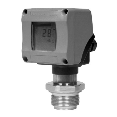
Pepperl+Fuchs Barcon PPC User manual

12
+–
3
Zero
Damping
on off
Span
Display
0,753
IO
BA 201O/98/en/07.01
Software version 1.0
52011571
Barcon Pressure Transmitter
Barcon PPC (HART)
Barcon LHC (HART)
Operating instructions

With regard to the supply of products, the current issue of the following document is applicable:
The General Terms of Delivery for Products and Services of the Electrical Industry, as published by
the Central Association of the "Elektrotechnik und Elektroindustrie (ZVEI) e.V.",
including the supplementary clause "Extended reservation of title".
We at Pepperl+Fuchs recognise a duty to make a contribution to the future.
For this reason, this printed matter is produced on paper bleached without the use of chlorine.

Barcon LHC/PPC (HART)
Short operating instructions
Date of Issue 25.10.2001
3
Short operating instructions
12
+–
3
Zero
Damping
on off
Span
Display
Local operation
with digital display
Remote operation
via HART protocol
Operation:
• Function of the display
Sect. 3.2
• Position and function of the
operating elements on the
electronic insert
Sect. 3.3
Commissioning on site:
• Sect. 4.1
Operation:
• with PACTware Sect. 3.4
• with Universal HART
Communicator Sect. 3.5
Commissioning
with remote communication:
• Sect. 4.2

Barcon LHC/PPC (HART)
Software history
4
Date of Issue 25.10.2001
Software history
Software version Valid operating
instructions (BA)
Device and
Software No. Software revision
Changes in
operating
instructions
1.0 07.01 8010 – –

Barcon LHC/PPC (HART)
Table of contents
Date of Issue 25.10.2001
5
Table of contents
Short operating instructions . . . . . 3
Software history . . . . . . . . . . . . . . . 4
Table of contents . . . . . . . . . . . . . . 5
Notes on safety . . . . . . . . . . . . . . . . 6
Safety conventions . . . . . . . . . . . . 7
1 Introduction . . . . . . . . . . . . . . . . . . 8
2 Installation . . . . . . . . . . . . . . . . . . . 9
2.1 Mechanical design of devices . . . . . . . . . . .9
2.2 Mounting instructions without
diaphragm seal . . . . . . . . . . . . . . . . . . . . . .13
2.3 Mounting instructions with
diaphragm seal . . . . . . . . . . . . . . . . . . . . . .15
2.4 Mounting accessories . . . . . . . . . . . . . . . .17
2.5 Electrical connection . . . . . . . . . . . . . . . . .18
3 Operation . . . . . . . . . . . . . . . . . . . 21
3.1 Access to the operating elements . . . . . .21
3.2 Function of the display . . . . . . . . . . . . . . .22
3.3 Position and function of the operating
elements on the electronic insert . . . . . . .22
3.4 Operation using PACTware®. . . . . . . . . . .23
3.5 Operating with the HART protocol via
universal HART communicator . . . . . . . . .24
4 Commissioning . . . . . . . . . . . . . . . 25
4.1 On-site commissioning . . . . . . . . . . . . . . . 25
4.2 Commissioning and operation using
communication . . . . . . . . . . . . . . . . . . . . . . 26
4.3 Locking/unlocking operation . . . . . . . . . . 28
4.4 Information on the measuring point . . . . . 29
5 Diagnosis and troubleshooting . . 30
5.1 Diagnosis of errors and warnings . . . . . . 30
5.2 Current simulation . . . . . . . . . . . . . . . . . . . 30
5.3 Reset . . . . . . . . . . . . . . . . . . . . . . . . . . . . . . 31
6 Maintenance and repair . . . . . . . . . 32
6.1 Repair . . . . . . . . . . . . . . . . . . . . . . . . . . . . . 32
6.2 Replacement parts . . . . . . . . . . . . . . . . . . . 32
6.3 Mounting the digital display . . . . . . . . . . . 33
6.4 Changing the electronic insert . . . . . . . . . 34
6.5 Changing the measuring cell . . . . . . . . . . 36
6.6 Changing the gasket . . . . . . . . . . . . . . . . . 36
7 Technical data . . . . . . . . . . . . . . . . 37
8 Matrix of parameters . . . . . . . . . . . 42
Index . . . . . . . . . . . . . . . . . . . . . . . . 43
Barcon LHC/PPC (HART)
Notes on safety
6
Date of Issue 25.10.2001
Notes on safety
Approved usage The Barcon is a pressure transmitter for measuring gauge or absolute pressure
depending on the version.
Mounting,
commissioning,
operation
The Barcon has been designed to operate safely in accordance with current technical,
safety and EU standards. If installed incorrectly or used for applications for which it is
not intended, however, it is possible that application-related dangers may arise, e. g.
product overspill by incorrect installation or adjustment. For this reason, the instrument
must be installed, connected, operated and maintained by personnel that are authorised
by the user of the facility and who are suitably qualified. The manual is to be read and
understood, and the instructions followed. Modifications and repairs to the device are
permissible only when they are expressly approved in the manual.
Explosion-
hazardous area
The measuring system used in the explosion-hazardous area must comply with all
existing national standards. The instrument can be supplied with the following
certificates as listed in the table. The certificates are designated by the last letters of the
order code on the nameplate (see table below).
Ensure that technical personnel are sufficiently trained.
All measurement and safety regulations which apply to the measuring points are to be
observed.
Table S.1 Certificates for applications in explosion hazardous areas
Code Certificate Protection
NA Standard None
EX ATEX ATEX II 1/2 G EEX ia IIC T6
E1 ATEX ATEX II 2 G EEX ia IIC T6
SX ATEX ATEX II 1/2 D EEX ia IIC T6
S2 ATEX ATEX II 1/3 D (non- Ex power supply)
E2 ATEX ATEX II 3 G EEx nV IIC T5 (Zone 2)
CG CSA General Purpose
C1 CSA CSA IS (suitable for Div. 2) Cl. I, II, III, Div. 1, Groups A … G
CD CSA CSA Cl. I, Div. 2, Groups A … D, Cl. II, III, Div. 1, Groups E … G
FM FM FM IS (non incendive) Cl. I, II, III, Div. 1, Groups A…G
FD FM FM DIP, Cl. II, III, Div. 1, Groups A … G
TI TIIS TIIS Ex ia IIC T6
7\SHFRGH%DUFRQ
ooo
ooo
oooo
oooo
ooooo
oo

Barcon LHC/PPC (HART)
Safety conventions
Date of Issue 25.10.2001
7
Safety conventions
In order to highlight safety-relevant or alternative operating procedures in the manual,
the following conventions have been used, each indicated by a corresponding icon in
the margin.
Safety conventions
Explosion protection
Electrical symbols
Symbol Meaning
Note!
A note highlights actions or procedures which, if not performed correctly, may
indirectly affect operation or may lead to an instrument response which is not planned
Caution!
Caution highlights actions or procedures which, if not performed correctly, may lead to
personal injury or incorrect functioning of the instrument
Warning!
A warning highlights actions or procedures which, if not performed correctly, will lead
to personal injury, a safety hazard or destruction of the instrument
Note!
Caution!
Warning!
Device certified for use in explosion hazardous area
If the device has this symbol embossed on its name plate it can be installed in an
explosion hazardous area
Explosion hazardous area
Symbol used in drawings to indicate explosion hazardous areas.
• Devices located in and wiring entering areas with the designation "explosion
hazardous areas" must conform with the stated type of protection
Safe area (non-explosion hazardous area)
Symbol used in drawings to indicate, if necessary, non-explosion hazardous areas.
• Devices located in safe areas stiill require a certificate if their outputs run into
explosion hazardous areas.
Direct voltage
A terminal to which or from which a direct current or voltage may be applied or
supplied
Alternating voltage
A terminal to which or from which an alternating (sine-wave) current or voltage may be
applied or supplied
Grounded terminal
A grounded terminal, which as far as the operator is concerned, is already grounded
by means of an earth grounding system
Protective grounding (earth) terminal
A terminal which must be connected to earth ground prior to making any other
connection to the equipment
Equipotential connection (earth bonding)
A connection made to the plant grounding system which may be of type e.g. neutral
star or equipotential line according to national or company practice

Barcon LHC/PPC (HART)
Introduction
8
Date of Issue 25.10.2001
1Introduction
Application The Barcon PPC and the Barcon LHC pressure transmitter measures the pressure of
gases, vapours and liquids and is used in all areas of chemical and process engineering.
Operating principle
Ceramic sensor
The system pressure acts directly on the rugged ceramic diaphragm of the pressure
sensor deflecting it by a maximum of 0.025 mm (0.0098 in). A pressure-proportional
change in the capacitance is measured by the electrodes on the ceramic substrate and
diaphragm. The measuring range is determined by the thickness of the ceramic
diaphragm.
Metal sensor
The process pressure deflects the separating diaphragm with a filling liquid transmitting
the pressure to a resistance bridge. The bridge output voltage, which is proportional to
pressure, is then measured and processed.
Fig. 1.1: Sensor construction
Measuring system The complete measuring system consists of
• Barcon pressure transmitter with 4 mA … 20 mA signal output with
superposed digital signal (HART communication) and
• power supply 11.5 V … 45 V DC, in Ex area 11.5 V … 30 V DC.
Operation can be carried out via:
• a digital display for operating and calling up measured values locally,
• the universal handheld HART Communicator,
• the Pepperl+Fuchs PACTware operating program.
Fig. 1.2: The measurement system
Electrode
Ceramic sensor Metal sensor
Diaphragm
Ceramic substrate Resistance
bridge
Filling fluid
Barcon 4 mA ... 20 mA
Non-Ex area:
11.5 V … 45 V DC
Ex-i area:
11.5 V … 30 V DC
Process

Barcon LHC/PPC (HART)
Installation
Date of Issue 25.10.2001
9
2 Installation
ContentsThis section describes:
• the mechanical design of Barcon,
• the mechanical installation of Barcon with and without diaphragm seal,
• the electrical connection.
2.1 Mechanical design of devices
lid (standard)
lid with lid lock
(Ex-version, only)
electronics
holder
central
mount
housing
F15
(stainless steel)
flat seal silicon 40 x 43 x 1
(set of 5, but included with
the sensor)
screws 3 x 10
(included)
screws 3 x 8
lid with sight glass: glass (Ex i)
lid with lid lock and
sight glass: glass
lid with sight glass: polycarbonate
display module complete
with retaining ring
retaining ring separate
profile seal 64.2 x 72.7 x 5
(set 5 pieces)
Mechanical design of Barcon with stainless steel housing
measuring cells
measuring range
0 bar ... 0,1 bar
0 bar ... 0,4 bar
0 bar ... 1 bar
0 bar ... 4 bar
0 bar ... 10 bar
0 bar ... 40 bar
-0,1 bar ... +0,1 bar
-0,4 bar ... +0,4 bar
-1bar ... +1 bar
-1bar ... +4 bar
-1bar ... +10 bar
–
–
–
–
–
–
–
–
–
–
–
high
pressure
absolute
pressure
negative
high press.
–
–
–
–
–
½ NPT
M20 x 1,5
G½
M12 x 1 plug
Harting plug
cable entry
electronic module HART
programmed with sensor parameters
(When ordering, please state the serial number
of the instrument (given on the nameplate).)

Barcon LHC/PPC (HART)
Installation
10
Date of Issue 25.10.2001
flat seal silicon 40 x 43 x 1
(set of 5, but included with
the sensor)
screws3x10
(included)
screws 3 x 8
display module complete
with retaining ring
retaining ring separate
lid with sightglass
incl. seal
lid
incl. seal
electronics
holder
housing
F18
(aluminium)
kit cover seal
(set 10 pieces
EPDM 70.0 x 3.0)
kit cover seal
(set 10 pieces
EPDM 70.0 x 3.0)
central mount
metal
PAL-clamp
inside
PAL-clamp
outside
PAL-
cable
safety loop for
cover with
certificate EEx d
M20 x 1,5
Mechanical design of Barcon with aluminium housing
½ NPT
M20 x 1,5
G½
M12 x 1 plug
Harting plug
cable entry
measuring cells
measuring range
0 bar ... 0,1 bar
0 bar ... 0,4 bar
0 bar ... 1 bar
0 bar ... 4 bar
0 bar ... 10 bar
0 bar ... 40 bar
-0,1 bar ... +0,1 bar
-0,4 bar ... +0,4 bar
-1bar ... +1 bar
-1bar ... +4 bar
-1bar ... +10 bar
–
–
–
–
–
–
–
–
–
–
–
high
pressure
absolute
pressure
negative
high press.
–
–
–
–
–
electronic module HART
programmed with sensor parameters
(When ordering, please state the serial number
of the instrument (given on the nameplate).)

Barcon LHC/PPC (HART)
Installation
Date of Issue 25.10.2001
11
angled disk
(standard)
complete with
3AllenscrewsM5x12
process connection
G½ flush membrane
process connection
welded with cell
(no spare part)
Process connection PPC-M10
Process connection PPC-M20
thread
G½ external
½ NPT external
½ NPT internal
PF ½ external
PT ½ external
M20 x 1,5 external
seal
FKM Viton
exchangeable thread 1.4435
PTFE+Hastelloy C
(two-piece)
FKM
FKM
NBR
EPDM
FFKM, Kalrez
FFKM, Chemraz
1)
O-ring 26.7 x 1.78
1) fof oxygene only
thread
G½ external
M20 x 1.5 external
½ NPT external, ¼ NPT internal
½ NPT internal, 11.4 mm internal
PT ½ external
G½ external, G¼ internal
G½ external, 11.4 mm internal
PF ½ external
G½ external, Hastelloy
½ NPT external, ¼ NPT internal, Hastelloy
exchangeable thread

Barcon LHC/PPC (HART)
Installation
12
Date of Issue 25.10.2001
Process connection LHC-M40
Diaphragm seals can be filled with different
liquids and can feature a multitude of
flange versions and sanitary couplings.
process connection
and cell welded together
Process connection LHC-M20
DIN 11851, DN 50
DIN 11851, DN 40
DIN 11864-1-A DN 40
DIN 11864-1-A DN 50
SMS 1½"
SMS 2"
Clamp 2"
Varivent 68 mm
DRD D = 65 mm
APV Inline PN 40
G2
2 NPT
process seals of the membrane
O-rings 26.7 x 1.78
FKM
FFKM Kalrez
FKM
EPM
NBR
1)
threaded boss 1.4435
measuring cell with sanitary couplings 1.4435
process seal
inside
process seal
inside
process seal
inside
FDA listed
1) for oxygene only

Barcon LHC/PPC (HART)
Installation
Date of Issue 25.10.2001
13
2.2 Mounting instructions without diaphragm seal
Barcon
without diaphragm seal
– PPC-M10, PPC-M20
– LHC-M20
The Barcon without diaphragm seal is mounted in the same way as a manometer. The
use of shut-off valves and pigtails is recommended. The position depends upon the
application.
• Measurement in gases:
Mount the shut-off valve above the tapping point so that condensate can
run back into the process.
Fig.2.1: Mounting on a shut-off valve for measuring gases
• Measurement in steam:
Mount with a pigtail above the tapping point.
The pigtail reduces the temperature in front of the diaphragm to almost
ambient temperature. Before start-up, the pigtail must be filled with water.
Fig. 2.2: left: Mounting with U-shaped pigtail for measuring steam
right: Mounting with circular pigtail for measuring steam

Barcon LHC/PPC (HART)
Installation
14
Date of Issue 25.10.2001
• Measurement in liquids:
Mount on the shut-off valve below the tapping point or at the same height
Fig.2.3: Mounting on a shut-off valve for measuring liquids
Mounting the PPC-M10 The PPC-M10 with metal sensor is available in the following versions:
• with flush-mounted diaphragm or
• with adapter and internal diaphragm.
The adapter can be screwed on or welded in.
A gasket is enclosed according to the material used and version.
Fig.2.4: PPC-M10 with flush-mounted diaphragm
3
3
4.3
3
G½
G½
G½
Ø 26.4
Ø 26.4
Ø 26.4
27
21.3
50
14 15
2.5
22 21
21
19.4
17
17
17
G½ external with O-ring
Viton seal O-ring 14 x 1.78
Viton or NBR
G½ external
Viton seal
DIN 3852 -E-G½
Teflon
Hastelloy spring
Teflon-backup
PTFE seal
DIN 3852-X-G½
Welded nozzle
Screwed plug Threaded hole

Barcon LHC/PPC (HART)
Installation
Date of Issue 25.10.2001
15
Fig.2.5: Barcon PPC-M10 with screwed or welded adapter. With screw adapter max. torque 80 Nm
2.3 Mounting instructions with diaphragm seal
Barcon
with diaphragm seal
– LHC-M40
The Barcon with diaphragm seal is screwed in, flanged or clamped, depending on the
type of diaphragm seal.
Fig.2.6: Diaphragm seal versions
• The protective cap of the diaphragm seal should only be removed just
before mounting in order to protect the diaphragm.
• The diaphragm of the diaphragm seal of the Barcon must not be dented or
cleaned with pointed or hard objects.
• The diaphragm seal and the pressure sensor together form a closed and
calibrated system which is filled with filling fluid through a hole in the upper
part of the sensor. The following rules should be observed:
- This hole is sealed and is not to be opened.
- The instrument should only be turned by the diaphragm seal at the point
provided and not by the housing.
Seal supplied
Welded
Process connection
flush-mounted diaphragm
With adapter internal
diaphragm
LHC with screw cap LHC with flange LHC with clamp

Barcon LHC/PPC (HART)
Installation
16
Date of Issue 25.10.2001
Mounting with
temperature spacers
The use of temperature spacers is recommended for constant extreme product
temperatures that can cause the maximum permissible ambient temperature of +85 °C
(+185 °F) to be exceeded.
• Note when mounting that the temperature spacer increases the maximum
height by 100 mm (3.94 in).
• Due to the water column in the temperature spacer, the increased height
also causes a zero point shift of approx. 10 mbar (0.15 psi).
Fig.2.7: Mounting with temperature spacers
Mounting with
capillary tubing
To protect from high temperature, moisture or vibration, or where the mounting point is
not easily accessible, the housing of the Barcon can be mounted with a capillary tube to
one side of the measuring point.
A bracket for mounting on a wall or pipe is available for this.
Fig.2.8: Mounting with capillary tubing and bracket away from the measuring point. Values in brackets
apply to instruments with a raised cover.
100
184.5
60.3
81
119.5
26 101 (121)
70
102.5
167
101 (121)26
3
Mounting point
away from
the measuring point
Measuring point:
• very moist
•hot
• strongly vibrating
• difficult to
access

Barcon LHC/PPC (HART)
Installation
Date of Issue 25.10.2001
17
2.4 Mounting accessories
PPC-M20:
wall and pipe mounting
with bracket
Fig. 2.9: left: Mounting with bracket on a vertical pipe
righ Mounting with bracket on a wall
Values in brackets apply to instruments with a raised cover.
PPC-M10:
wall and pipe mounting
with bracket
Fig. 2.10: left: Mounting with bracket on a vertical pipe
righ Mounting with bracket on a wall
Values in brackets apply to instruments with a raised cover.
159
98 (118)
32
94
3
176
60.3
81
111
32 97 (117)
70
60.3
6
184.5
60.3
81
119.5
26 113(133)
70
60.3
6
167.5
114 (134)26
102.5
3

Barcon LHC/PPC (HART)
Installation
18
Date of Issue 25.10.2001
2.5 Electrical connection
Transposed, screened two-wire cabling is recommended for the connecting cable.
Max. wire diameter: 2.5 mm2permanently attached cable
The power supply voltage is:
• Non-Ex: 11.5 V… 45 V DC
• Ex i area: 11.5 V … 30 V DC
Internal protection circuits against reverse polarity, HF interference and overvoltage
peaks.
A test signal can be measured using the terminal plugs for this purpose without
interrupting measurement.
Cable connection • Unscrew the cover
• If present, remove the retainer ring with digital display. In addition:
- Push up the latch with the arrow until the grip of the retaining ring is
audibly released.
- Loosen the retainer ring carefully to prevent the display cable from
breaking. The plug of the display can remain plugged in.
• Insert the cable through the cable entry
• Connect the cable wires as shown in the connection diagram.
• Where appropriate, replace the retainer ring with digital display.The grip of
the retainer ring clips in with an audible click.
• Screw down the cover
Fig.2.11: Lifting off the display and removing the retaining ring
Observe all local regulations for applications in the EEx i area!
Fig.2.12: Graph showing load
To loosen the holder from the electronic
insert, push latch with arrow upwards.
U/V
R/Ω
0
1522
1000
840
500
11.5 30 45
20
Standard
EEx ia IIC T6

Barcon LHC/PPC (HART)
Installation
Date of Issue 25.10.2001
19
Note!
Terminal 3 on the electronic insert is for grounding and is already wired internally. If the
connection cable has a screening or ground cable within it, then this may only be
connected to the grounding terminal of the housing and not to Terminal 3 (see
connecting diagrams).
Fig.2.13: Connection
Plug
Plug assignment
Terminal Function Wire colour code
Harting plug 1
2
8
+
-
PE
Blue (BL)
Brown (BN)
Green-Yellow
(GNYE)
Plug M12 x 1 +
-
PE
Red (RD)
Black (BK)
Green (GN)
Note!
12
+–
3
12
+
+
–
–
3
Zero
Damping
on off
Span
Display
Test 4 mA ... 20 mA
Always connect the screening or ground cable
(if present) to the internal ground terminal of the
housing, not to Terminal 3.
12
3
8
7
6
5
4
–
+

Barcon LHC/PPC (HART)
Installation
20
Date of Issue 25.10.2001
Connecting the
handheld terminal
• Do not replace the battery of the handheld terminal in the explosion
hazardous area.
• For a BARCON with FM or CSA certificate: Electrical connection according
to "Installation drawing" (enclosed in the packing of the Barcon).
• For correct transmission of the communication signal, a minimum
resistance of 250
W
must be present between the connection points and
the power supply.
Fig.2.14: The handheld terminal can be connected anywhere along the 4 mA … 20 mA line.
Connecting the
HART- Modem
for operating with
PACTware
The HART modem connects the Barcon with a HART protocol to the RS 232 C serial
interface of a personal computer. This enables the Barcon to be remotely operated with
operating program PACTware.
Fig.2.15: The HART modem can be connected anywhere along the 4 mA … 20 mA line.
4 mA ... 20 mA min. 250 Ω
IO
IO
12
+ –
3
Zero
Damping
on off
Span
Display
Transmitterpower supply e. g. KFD2-STL3-Ex.1
any device
12
+ –
3
Zero
Damping
on off
Span
Display
4 mA ... 20 mA
Transmitter power supply e. g. KFD2-STL3-Ex.1
PC with PACTware
minimum
Total resistance
250
W
HART
modem
This manual suits for next models
1
Table of contents
Other Pepperl+Fuchs Transmitter manuals

Pepperl+Fuchs
Pepperl+Fuchs LHCR-51 User manual

Pepperl+Fuchs
Pepperl+Fuchs HiD2024 User manual

Pepperl+Fuchs
Pepperl+Fuchs LHCR-51 User manual

Pepperl+Fuchs
Pepperl+Fuchs BARCON User manual

Pepperl+Fuchs
Pepperl+Fuchs LHC-M51 User manual

Pepperl+Fuchs
Pepperl+Fuchs HiD2022 Series User manual

Pepperl+Fuchs
Pepperl+Fuchs SIL KCD2-STC-1.HC User guide