manuals.online logo
Brands
  1. Home
  2. •
  3. Brands
  4. •
  5. Pepperl+Fuchs
  6. •
  7. Transmitter
  8. •
  9. Pepperl+Fuchs HiD2024 User manual

Pepperl+Fuchs HiD2024 User manual

Release date 2014-09-16 17:03 Date of issue 2014-09-16 185930_eng.xml
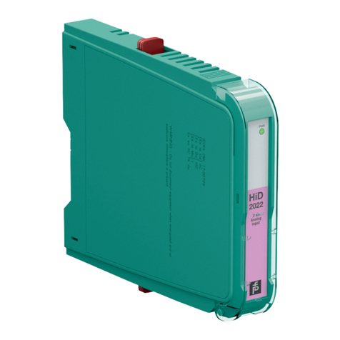
HiD2024
1
Refer to "General Notes Relating to Pepperl+Fuchs Product Information".
Pepperl+Fuchs Group USA: +1 330 486 0002 Singapore: +65 6779 9091Germany: +49 621 776 2222
www.pepperl-fuchs.com [email protected].com [email protected].com [email protected]
SMART Transmitter Power Supply/Current Driver
HiD2024
Termination Board
+
-
+
-
+
-
+
-
+
-
+
-
+
-
+
-
+
-
Zone 2
Div. 2
1
5
2
4
3
8
7
6
11
14
12
15
13
16
17
18
HARTHARTHARTHART
I
II
III
IV
I
II
III
IV
Zone 0, 1, 2
Div. 1, 2
VmA
24V DC
HART
I
PSL2
5a
5b
1a
1b
3a
3b
7a
7b
SL1
8a
7a
10a
9a
9b
10b
8b
7b
1a, 1b
2a, 2b
HART
VmA
HART
I
P
HART
VmA
HART
I
P
HART
VmA
HART
I
P
HART
Connection
Assembly
• 4-channel isolated barrier
• 24 V DC supply (bus powered)
• Analog in or analog out signals
• Sink and source mode outputs
• SMART pass-through
Function
This isolated barrier is used for intrinsic safety applications. It
operates as a SMART transmitter power supply or as a
repeater.
Bi-directional communication is supported for SMART
transmitters that use current modulation to transmit data and
voltage modulation to receive data.
The outputs are fully isolated from the inputs, the power
supply, and each other.
An open field circuit presents a high impedance to the control
side to allow alarm conditions to be monitored by control
systems.
This module mounts on a HiD Termination Board.
Features
HiD
2024
4 ch
Transmitter
Power
Supply/
Current
Driver
PWR
CH 1
ADJUST
CH 2
CH 3
CH 4
LED green:
Power supply
Front view
Potentiometer for calibration:
channel 1 ... 4
Switch 1 ... 4
Place for
labeling
Release date 2014-09-16 17:03 Date of issue 2014-09-16 185930_eng.xml
Technical data HiD2024
2
Refer to "General Notes Relating to Pepperl+Fuchs Product Information".
Pepperl+Fuchs Group USA: +1 330 486 0002 Singapore: +65 6779 9091Germany: +49 621 776 2222
www.pepperl-fuchs.com [email protected].com [email protected].com [email protected]
General specifications
Signal type Analog input
Supply
Connection SL1: 1a(-), 1b(-); 2a(+), 2b(+)
Rated voltage 20.4 ... 30 V DC via Termination Board
Ripple ≤10 %
Rated current 140 mA at 24 V and 20 mA
Power loss ≤1.8 W at 20 mA
Power consumption ≤3.3 W at 20 mA
Hazardous area connection
Number of channels 4
Connection SL2: 5a(+), 5b(-); 1a(+), 1b(-); 3a(+), 3b(-); 7a(+), 7b(-)
Input signal 4 ... 20 mA , limited to approx. 30 mA
Available voltage ≥15 V at 20 mA
Output signal 4 ... 20 mA
Output load 0 ... 650 Ω
Safe area connection
Number of channels 4
Connection SL1: 8a(+), 7a(-); 10a(+), 9a(-); 9b(+), 10b(-); 8b(+), 7b(-)
Input signal 4 ... 20 mA
Input resistance > 100 kΩat max. 23 V, with field wiring open
Voltage drop approx. 6 V or internal resistance 300 Ωat 20 mA
Output signal 4 ... 20 mA or 1 ... 5 V (on 250 Ω, 0.1 % internal shunt)
4 ... 20 mA (sink mode), operating voltage 15 ... 26 V
Output load 0 ... 300 Ω(source mode)
Ripple 20 mV rms
Transfer characteristics
Deviation at 20 °C (68 °F)
≤± 0.1 % incl. non-linearity and hysteresis (source mode 4 ... 20 mA)
≤± 0.2 % incl. non-linearity and hysteresis (sink mode 4 ... 20 mA)
≤± 0.2 % incl. non-linearity and hysteresis (source mode 1 ... 5 V)
≤± 0.2 % incl. non-linearity and hysteresis (analog output mode 4 ... 20 mA)
Influence of ambient temperature < 2 µA/K (0 ... 60 °C (32 ... 140 °F)); < 4 µA/K (-20 ... 0 °C (-4 ... 32 °F))
Frequency range field side into the control side: bandwidth with 0.5 Vpp signal 0 ... 3 kHz (-3 dB)
control side into the field side: bandwidth with 0.5 Vpp signal 0 ... 3 kHz (-3 dB)
Rise time 10 to 90 % ≤20 ms
Electrical isolation
Output/power supply basic insulation according to IEC 62103, rated insulation voltage 50 Veff
Directive conformity
Electromagnetic compatibility
Directive 2004/108/EC EN 61326-1:2006
Conformity
Electromagnetic compatibility NE 21:2006
For further information see system description.
Degree of protection IEC 60529
Ambient conditions
Ambient temperature -20 ... 60 °C (-4 ... 140 °F)
Mechanical specifications
Degree of protection IP20
Mass approx. 140 g
Dimensions 18 x 106 x 128 mm (0.7 x 4.2 x 5 in)
Mounting on Termination Board
Coding pin 1 and 3 trimmed
For further information see system description.
Data for application in connection
with Ex-areas
EC-Type Examination Certificate CESI 02 ATEX 086 , for additional certificates see www.pepperl-fuchs.com
Group, category, type of protection ¬II (1)G [Ex ia Ga] IIC , ¬II (1)D [Ex ia Da] IIIC
Input Ex ia, Ex iaD
Supply
Maximum safe voltage Um250 V AC (Attention! Umis no rated voltage.)
Equipment
Voltage Uo25.2 V
Current Io93 mA
Release date 2014-09-16 17:03 Date of issue 2014-09-16 185930_eng.xml
Technical data HiD2024
3
Refer to "General Notes Relating to Pepperl+Fuchs Product Information".
Pepperl+Fuchs Group USA: +1 330 486 0002 Singapore: +65 6779 9091Germany: +49 621 776 2222
www.pepperl-fuchs.com [email protected].com [email protected].com [email protected]
Switches 1 ... 4
Potentiometer 1 ... 4
The front-mounted potentiometers are used for fine adjustment of current transfer. The factory-setting of the device is calibrated
to the function transmitter power supply. If using the device as current driver, the Offset of the output stage can calibrated via the
potentiometers.
Configure the device in the following way:
• Push the red Quick Lok Bars on each side of the device in the upper position.
• Remove the device from Termination Board.
• Set the DIP switches according to the figure.
The device operates as a SMART transmitter power supply or as a repeater:
• As a SMART transmitter power supply, it provides a fully floating supply to power up to four 2-wire transmitters in a hazardous
area, repeating the current to drive a safe area source or sink mode output.
• As a repeater, it transmits a 4 mA ... 20 mA input signal from a control system to drive HART I/P converters, valve actuators,
and displays in a hazardous area.
Power Po586 mW
Statement of conformity PF 11 CERT 2109 X , observe statement of conformity
Group, category, type of protection,
temperature class
¬II 3G Ex nA IIC T4 Gc
Electrical isolation
Input/Output safe electrical isolation acc. to EN 60079-11: 2007, voltage peak value 375 V
Input/power supply safe electrical isolation acc. to EN 60079-11: 2007, voltage peak value 375 V
Directive conformity
Directive 94/9/EC EN 60079-0:2009, EN 60079-11:2007, EN60079-15:2005 , EN 60079-26:2007 , EN 61241-11:2006
General information
Supplementary information EC-Type Examination Certificate, Statement of Conformity, Declaration of Conformity, Attestation of
Conformity and instructions have to be observed where applicable. For information see www.pepperl-
fuchs.com.
The pins for this device are trimmed to polarize it according to its safety parameter. Do not change!
For further information see system description.
Configuration
CAUTION
Refer to the instruction
manual to install and
operate the unit
CH 1
ON
CH 2
ON
4
1
4
1
4
1
4
1
CH 3
ON
CH 4
ON
SWITCH SETTINGSFUNCTION
for
EACH CHANNEL
Analog input with
source output 4-20mA
Analog input with
source output 1-5V OFF ON OFF ON
1234
Analog input with
sink output 4-20mA OFF OFF ON OFF
OFF OFF OFF ON
Analog output ON OFF ON OFF
Additional information

Other manuals for HiD2024

1

Other Pepperl+Fuchs Transmitter manuals

Pepperl+Fuchs LHCR-51 User manual

Pepperl+Fuchs

Pepperl+Fuchs LHCR-51 User manual

Pepperl+Fuchs LHC-M51 User manual

Pepperl+Fuchs

Pepperl+Fuchs LHC-M51 User manual

Pepperl+Fuchs Barcon PPC User manual

Pepperl+Fuchs

Pepperl+Fuchs Barcon PPC User manual

Pepperl+Fuchs SIL KCD2-STC-1.HC User guide

Pepperl+Fuchs

Pepperl+Fuchs SIL KCD2-STC-1.HC User guide

Pepperl+Fuchs BARCON User manual

Pepperl+Fuchs

Pepperl+Fuchs BARCON User manual

Pepperl+Fuchs HiD2022 Series User manual

Pepperl+Fuchs

Pepperl+Fuchs HiD2022 Series User manual

Pepperl+Fuchs LHCR-51 User manual

Pepperl+Fuchs

Pepperl+Fuchs LHCR-51 User manual

Popular Transmitter manuals by other brands

THOMSON IOX Series Maintenance manual

THOMSON

THOMSON IOX Series Maintenance manual

Teradek Ranger quick start guide

Teradek

Teradek Ranger quick start guide

signia 650003 user guide

signia

signia 650003 user guide

Chamberlain RTXW2 quick start guide

Chamberlain

Chamberlain RTXW2 quick start guide

Bellman & Symfon BE1431 user manual

Bellman & Symfon

Bellman & Symfon BE1431 user manual

SILENTSYSTEM TX-350-CH5 owner's guide

SILENTSYSTEM

SILENTSYSTEM TX-350-CH5 owner's guide

WIKA C-10 operating instructions

WIKA

WIKA C-10 operating instructions

Taurus ALPATEC VILNA 600 manual

Taurus

Taurus ALPATEC VILNA 600 manual

SGM LEKTRA METER Technical documentation

SGM LEKTRA

SGM LEKTRA METER Technical documentation

RKI Instruments 65-2434RK Operator's manual

RKI Instruments

RKI Instruments 65-2434RK Operator's manual

Emerson Rosemount 3051P Reference manual

Emerson

Emerson Rosemount 3051P Reference manual

Honeywell STT25D Operator's manual

Honeywell

Honeywell STT25D Operator's manual

Dwyer Instruments 616WL-2 Installation and operating instructions

Dwyer Instruments

Dwyer Instruments 616WL-2 Installation and operating instructions

NIVELCO NIPRESS D 9 Series user manual

NIVELCO

NIVELCO NIPRESS D 9 Series user manual

Vega VEGABAR 82 operating instructions

Vega

Vega VEGABAR 82 operating instructions

Miller 907732013 owner's manual

Miller

Miller 907732013 owner's manual

Vanco Evolution EVOIPLITE instructions

Vanco

Vanco Evolution EVOIPLITE instructions

Embedded Solutions Bluetooth R91007G manual

Embedded Solutions

Embedded Solutions Bluetooth R91007G manual

manuals.online logo
manuals.online logoBrands
  • About & Mission
  • Contact us
  • Privacy Policy
  • Terms and Conditions

Copyright 2025 Manuals.Online. All Rights Reserved.