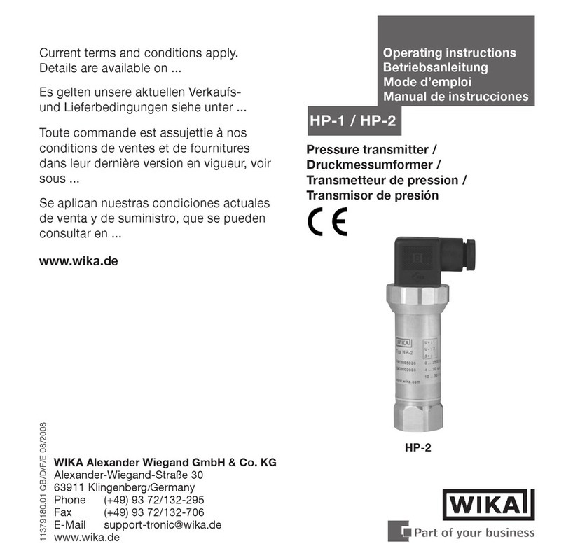
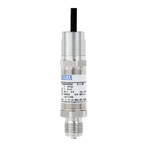
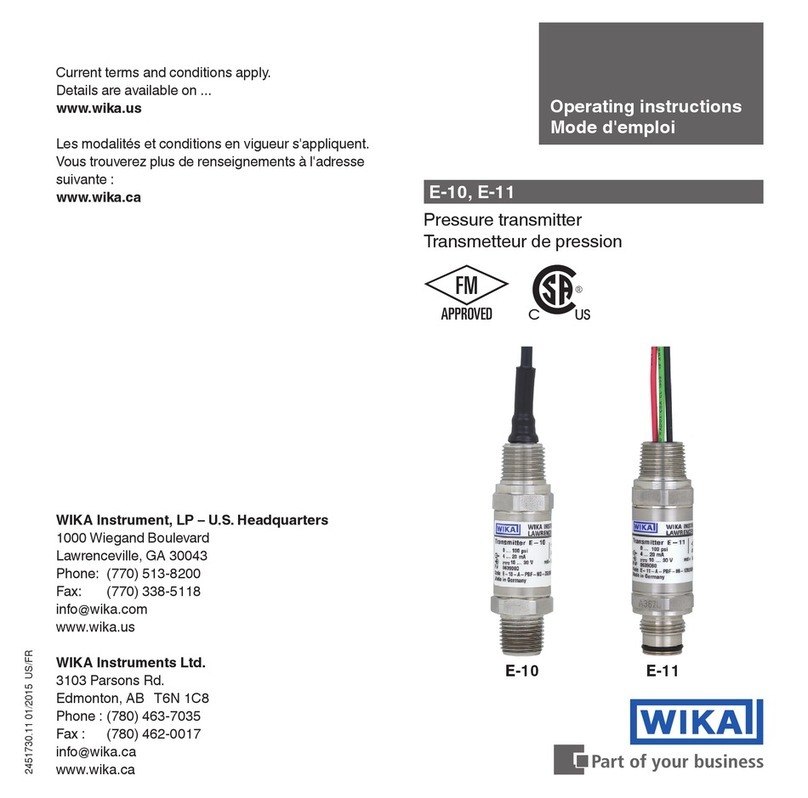
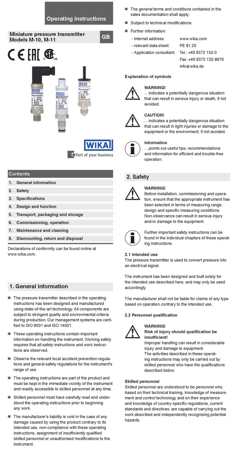
WIKA C-10 User manual

1
GBF
Operating instructions
Betriebsanleitung
Mode d’emploi
WIKA Alexander Wiegand GmbH & Co. KG
Alexander-Wiegand-Straße 30
63911 Klingenberg/Germany
Tel. (+49) 93 72/132-8952
Fax (+49) 93 72/132-706
E-Mail [email protected]
www.wika.de
C-10
GB
GB
Compact Pressure Transmitter for OEM-Applications
DKompakt-Druckmessumformer für OEM Anwendungen
Transmetteur de pression compact pour applications OEM
1439022.06 GB/D/F 12/2003

2
1. General information
2. Safety Instructions
3. Installation
4. Technical data
5. Wiring
WIKA Global
ontent
GB
ontenu
F
1. Allgemeines
2. Sicherheitshinweise
3. Montage
4. Technische Daten
5. Elektrischer Anschluss
WIKA Global
Inhalt
D
1. Généralités
2. onsignes de sécurité
3. Montage
4. aractéristiques techniques
5. Branchement électrique
WIKA Global
Current terms and conditions apply.
Details are available on
www.wika.de/download
Es gelten unsere aktuellen Verkaufs- und
Lieferbedingungen siehe unter
www.wika.de/download
Toute commande est assujettie à nos conditions
de ventes et de fournitures dans leur dernière
version en vigueur, voir sous
www.wika.de/download

3
FDGB
Instruction
!
Hinweis
!
Remarque
!
Bitte untersuchen Sie die Geräte auf eventuell aufgetretene Transportschäden. Sind
offensichtlich Schäden vorhanden, teilen Sie dies bitte dem Transportunternehmen und
WIKA unverzüglich mit.
The following installation and operating instructions have been compiled by us with great care but it is not
feasible to take all possible applications into consideration. These installation and operation instructions
should meet the needs of most pressure measurement applications. If questions remain regarding a
specific application, you can obtain further information (data sheets, instructions, etc.) via our Internet
address (www.wika.de / www.wika.com / download) or contact WIKA for additional technical support (see
WIKA Global).
WIKA pressure transmitters are carefully designed and manufactured using state-of-the-art technology.
Every component undergoes strict quality inspection before assembly and each instrument is fully tested
prior to shipment.
Please inspect the equipment for possible damage during transportation. Should there be
any obvious damage, please inform the transport company and WIKA without delay.
Die nachfolgenden Einbau- und Bedienungshinweise haben wir mit Sorgfalt zusammengestellt. Es ist
jedoch nicht möglich, alle erdenklichen Anwendungsfälle zu berücksichtigen. Sollten Sie Hinweise für Ihre
spezielle Aufgabenstellung vermissen, können Sie über unsere Internet Adresse (www.wika.de /
www.wika.com / download) weitere Informationen (Datenblätter, Hinweise, etc.) erhalten oder sich mit
einem unserer Anwendungsberater (siehe WIKA Global) in Verbindung setzen.
Veuiller s.v.p. contrôler les appareils afin de déterminer tout endommagement éventuel
subi en cours de transport. En cas de dommages manifestes, veuillez les déclarer
immédiatement à lentreprise de transport et à WIKA.
Les instructions de montage et de service présentées ci-après ont été établi avec grand soin. Il reste
toutefois impossible denvisager tous les cas dapplications possibles. Dans le cas où vous constateriez
des lacunes dans ces instructions pour les tâches spéciales quil vous faut exécuter, vous avez la
possibilité de recevoir des compléments dinformations (fiches de caractéristiques, remarques etc.) sous
notre adresse internet (www.wika.de / www.wika.com / download) ou par contact direct avec notre
conseiller applications(voir WIKA Global).
C-10
1. Généralités
La conception et la fabrication des transdmetteurs de mesure WIKA , tels que décrits dans les
instructions de service, satisfont aux toutes dernières règles de lart. Tous les composants sont soumis en
cours de fabrication à un contrôle stricte des critères de qualité.
1. Allgemeines
Die in der Betriebsanleitung beschriebenen WIKA-Druckmessumformer werden nach den neuesten
Erkenntnissen konstruiert und gefertigt. Alle Komponenten unterliegen während der Fertigung strengen
Qualitätskriterien.
1. General information

4
C-10 FDGB
Warnung
!
2. Sicherheitshinweise
Beachten Sie unbedingt vor Montage, Inbetriebnahme und Betrieb, dass das richtige
Druckmessgerät hinsichtlich Messbereich, Ausführung und aufgrund der spezifischen
Messbedingungen der geeignete messstoffberührte Werkstoff (Korrosion) ausgewählt
wurde. Weiter sind die entsprechenden nationalen Sicherheitsvorschriften
(z. B.: VDE 0100) zu beachten.
Bei Nichtbeachten entsprechender Vorschriften können schwere Körperverletzungen und/oder
Sachschäden auftreten.
Druckmessgeräte nur durch ausgebildetes und vom Anlagenbetreiber autorisiertem Fachpersonal
montieren lassen.
Bei gefährlichen Messstoffen wie z.B. Sauerstoff, Acetylen, brennbaren oder giftigen
Stoffen, sowie bei Kälteanlagen, Kompressoren etc. müssen über die gesamten allgemeinen Regeln
hinaus die jeweils bestehenden einschlägigen Vorschriften beachtet werden.
Bitte beachten Sie die Betriebsparameter gemäß Punkt Technische Daten.
Ein anderer Betrieb als der in der folgenden Anleitung beschriebene ist bestimmungswidrig und muss
deshalb ausgeschlossen werden. Können Störungen nicht beseitigt werden, ist das Gerät außer
Betrieb zu setzen und gegen versehentliche Inbetriebnahme zu schützen. Reparaturen dürfen nur vom
Hersteller durchgeführt werden. Eingriffe und Änderungen am Gerät, welche nicht in dieser Betriebs-
anleitung beschrieben sind, sind unzulässig.
Überlastgrenze des entsprechenden Messbereiches nicht überschreiten!
Alle Anschlüsse dürfen nur im drucklosen Zustand geöffnet werden!
Messstoffreste in ausgebauten Druckmessgeräten können zur Gefährdung von Menschen, Umwelt
und Einrichtung führen. Ausreichende Vorsichtsmaßnahmen sind zu ergreifen.
2. onsignes de sécurité
Veuillez absolument prendre en considération, avant le montage, la mise en service et
l'exploitation, que vous avez choisi linstrument adéquat quant à l'étendue de mesure,
le modèle et en raison des conditions de mesures spécifiques, la matière appropriée
pour les pièces en contact avec le fluide (corrosion). Par ailleurs, les réglements
nationales de sécurité (par exemple: VDE 0100) sont à respecter.
Le non-respect des instructions correspondantes est susceptible d'entraîner des risques de blessures
et/ou des dégâts matériels. Seul du personnel qualifié autorisé par le responsable de l'installation doit
installer des instruments. Pour les fluides dangereux comme par exemple l'oxygène, l'acétylène, les
matières combustibles ou nocives, ainsi que pour les systèmes frigorifiques, les compresseurs etc. il
faut en plus des règles techniques courantes tenir compte des prescriptions spécifiques. Veuillez
respecter les paramètres d'utilisation selon le point "caractéristiques techniques". Une autre
utilisation que celle prévue dans les instructions décrites ci-après est contraire aux prescriptions et doit
donc être exclue. Si des perturbations ne peuvent pas être éliminées, l'appareil doit être mis hors
service et protégé contre une mise en service intempestive. Des réparations ne doivent être effectuées
que par le fabricant. Des interventions et transformations sur l'appareil, qui ne sont pas décrit au mode
demploi, sont inadmissibles. Ne jamais dépasser la limite de surpression!
Les raccordements ne doivent être ouverts qu'en état exempt de pression!
Des restes de fluides mesurés se trouvant dans des instruments démontés peuvent mettre en danger
les personnes, l'environnement et les installations. Des mesures de sécurités appropriées sont à prendre.
2. Safety Instructions
aution
!Prior to installing, starting and operating a pressure measuring instrument the user must
ensure that the appropriate instrument has been selected with regard to scale range
and performance and that the wetted parts material are compatible with the media
being measured. In addition the relevant national safety regulations (e.g.: VDE 0100) have to be
observed.
Serious injuries and / or damage can occur should the relevant regulations not be observed.
Only qualified persons authorised by the plant manager are permitted to install and service the pressure
measuring instruments. Dangerous pressure media such as oxygen, acetylene, flammable gases or
liquids and toxic gases or liquids as well as instruments for refrigeration plants or compressors etc.
require attention above the standard regulations. Here the specific safety codes or regulations must be
considered. Please observe the ambient and working conditions outlined in section "Technical data".
Any operation other than that described in the following instructions is inconsistent with the provisions
and has to be excluded for that reason.
If the instrument should become damaged or unsafe for operation it should be removed from service
and marked to prevent it from being used again accidentally. Repairs may be performed by the
manufacturer only. The instrument must not be interfered with or changed in any other way than
discribed. Do not exceed overpressure safety of the respective pressure range!
All pressure connections may only be opened after the system is without pressure!
Remaining media in the pressure port may be hazardous or toxic. This should be considered when
handling or storing the instrument after removal!
!
Avertissement

5
C-10 FDGB
*)
*) Connectors are not included in delivery / Gegenstecker sind nicht im Lieferumfang enthalten /
Les connectors ne sont pas compris dans la livraison.
Circular connector, -pin /
Rundsteckverbinder,
-polig /
Connecteur, plots
M 12x1
IP 65
Order code /
Bestellcode /
Code de commande: M
Mini L- connector
G-series/
Miniatur-Winkelsteck-
verbinder G-Serie /
Connecteur coudé mini,
G-Serie
IP 65 Order code /
Bestellcode /
Code de commande: II
Flying leads /
Kabelausgang /
Sortie câble,
IP 67
Order code /
Bestellcode /
Code de
commande: DL
Pressure connections / Druckanschlüsse / Raccord de pression
ase / Gehäuse / Boîtier
G 1/
EN 837
Order code / Bestell-
code / Code de
commande: GB
For tapped holes and welding sockets please see data sheet IN 00.14 or www.wika.de/download
Einschraublöcher und Einschweißstutzen siehe Datenblatt IN 00.14 oder unter www.wika.de/download
Pour les taraudages et les embases à souder voir fiche technique IN 00.14 ou www.wika.de/download
Others on request / andere auf Anfrage /autres sur demande
G 1/
DIN 3852-E
Order code / Bestell-
code / Code de
commande: HD
1/ NPT
per Nominal size for US standard
tapered pipe thread NPT /
nach Nennmaße für US-Standard
kegeliges Rohrgewinde NPT /
Version standard selon norme US
NPT
Order code /Bestellcode / Code de
commande: NB
3. Installation / Montage / Montage (Dimensions in mm / Abmessungen in mm / Dimensions en mm)
Others on request / andere auf Anfrage /autres sur demande

6
FDGB
C-10
Dimensions Example / Bemaßungs-Beispiel /
Exemple de dimensions
Product label / Typenschild / plaque de
fabrication
max. 50 Nm
Instruction
!To prevent damaging the
pressure transmitters diaphragm,
do not use pointed or hard
objects for cleaning.
WIKA pressure transmitters require no
maintenance!
Recommended recalibration cycle: 1 year.
WIKA reserves the right to alter these technical
specifications.
Hinweis
!Um die Membrane des Druckan-
schlusses nicht zu beschädigen,
zur Reinigung keine spitzen bzw.
harten Gegenstände verwenden.
WIKA Druckmessgeräte sind wartungsfrei !
Empfohlener Nachkalibrier-Zyklus: 1 Jahr
Technische Änderungen vorbehalten.
Remarque
!Pour empêcher lendommage-
ment de la membrane du raccord
de pression, ne jamais utiliser
des objects pointus ou durs pour
le nettoyage.
Les transmetteurs WIKA ne demandent aucune
maintenance!
Il est recommandé de procédur à un ré-
étalonnage tous les ans.
WIKA se réserve le droit de modifier les présentes
spécifications.
S #
: Signal / Signal / Signal de sortie
: Power Supply / Hilfsenergie /
Alimentation
: Serial No. / Fabrik-Nr. / No. Série
: Product No. / Erzeugnis-Nr. /
Code Article
P #
Pin assignment/
Anschlussbelegung/
Position des connections
(With flying lead: Wiring colours /
Bei Kabel: Aderfarben zur Belegung /
avec câble dénundé et étamé: Code couleurs)
Coded manufacture date/
Codiertes Herstelldatum/
Date de fabrication (code)

7
GB
4. Technical data
C-10
Output signal and allowed load
Output current (2-wire-system)
... 20 mA: RA < (UB 10 V) / 0.02 A in Ohm and UB in Volt
Output current (3-wire-system)
0 ... 20 mA: RA < (UB - 3 V) / 0.02 A in Ohm and UB in Volt
Output voltage (3-wire-system)
0 ... 5 V: RA >5 kOhm
0 ... 10 V: RA >10 kOhm
... 20 mA, 2-wire-system
permitted range
Specifications Model C-10
Pressure ranges bar 0.25 0.4 0.6 1 1.6 2.5 4 6 10 16
Over pressure safety bar 224510 10 17 35 35 80
Burst pressure bar 2.4 2.4 4.8 6 12 12 20.5 42 42 96
Pressure ranges bar 25 40 60 100 160 250 400 600 1000
Over pressure safety bar 50 80 120 200 320 500 800 1200 1500
Burst pressure bar 250 400 550 800 1000 1200 1700 2400 3000
{Absolute pressure: 0 ... 0.25 bar abs to 0 ... 16 bar abs}
{Special pressure range 800 ... 1200 mbar abs}
Materials
n Wetted parts Stainless steel
n Case Stainless steel
Internal transmission fluid Synthetic oil, only for pressure ranges up to 0 ... 16 bar
{Halocarbon oil for oxygen applications} 1)
Hilfsenergie UBDC V 10 < UB ≤ 30 (14 ... 30 with signal output 0 ... 10 V)
Response time (10 ... 90 %) ms < 1 (< 10 ms at medium temperatures below -30 °C
for pressure ranges up to 16 bar)
Accuracy *) % of span ≤ 1.0 (limit point calibration)
included Hysteresis % of span ≤ 0.5 (BFSL)
Repeatability % of span ≤ 0.05
1-year stability % of span ≤ 0.2 (at reference conditions)
Permissible temperature of
n Medium -30 ... +100 °C {-40...+125°C} -22 ... +212 °F {-40 ... +257°F}
n Ambient -30 ... + 85 °C -22 ... +185 °F
n Storage -40 ... +100 °C -40 ... +212 °F
n Compensated 0 ... + 80 °C 32 ... +176 °F
Temperature coefficients in
compensated temp range
n Mean TC of zero % of span ≤ 0.3 / 10 K
n Mean TC of range % of span ≤ 0.2 / 10 K
a- conformity 89/336/EWG interference emission and immunity see EN 61326
97/23/EG Pressure equipment directive, Appendix 1
Shock resistance g1000 according to IEC 60068-2-27 (mechanical shock)
Vibration resistance g20 according to IEC 60068-2-6 (vibration under resonance)
Wiring protection Protected against reverse polarity, overvoltage and
short circuiting
Ingress protection per Per IEC 60529 / EN 60529, see section 3, Installation
Weight kg Approx. 0.1
1) Media temperature for oxygen version: -30 ... +60 °C (-22 ... 140 °F).
Cannot be manufactured for absolute pressure ranges < 1 bar abs.
*) Including linearity, hysteresis and reproducibility.
Limit point calibration in vertical mounting position with lower pressure connection.
{ } Items in curved brackets { } are optional extras for additional price.

8
D
C-10
4. Technische Daten
Ausgangssignal und zulässige Bürde
Stromausgang (2-Leiter)
... 20 mA: RA < (UB 10 V) / 0,02 A in Ohm und UB in Volt
Stromausgang (3-Leiter)
0 ... 20 mA: RA < (UB - 3 V) / 0,02 A in Ohm und UB in Volt
Spannungsausgang (3-Leiter)
0 ... 5 V: RA >5 kOhm
0 ... 10 V: RA >10 kOhm
... 20 mA, 2-Leiter
zulässiger Bereich
Technische Daten Typ C-10
Messbereich bar 0,25 0,4 0,6 1 1,6 2,5 4 6 10 16
Überlastgrenze bar 2 2 4 5 10 10 17 35 35 80
Berstdruck bar 2,4 2,4 4,8 6 12 12 20,5 42 42 96
Messbereich bar 25 40 60 100 160 250 400 600
1000
Überlastgrenze bar 50 80 120 200 320 500 800
1200 1500
Berstdruck bar 250 400 550 800
1000 1200 1700 2400 3000
{Absolutdruck: 0 ... 0,25 bar abs bis 0 ... 16 bar abs}
{Sondermessbereich 800...1200 mbar abs}
Werkstoff
n Messstoffberührte Teile CrNi-Stahl
n Gehäuse CrNi-Stahl
Interne Übertragungsflüssigkeit Synthetisches Öl, nur bei Messbereichen bis 16 bar
{Halocarbonöl für Sauerstoff-Ausführungen} 1)
Hilfsenergie UBDC V 10 < UB ≤ 30 (14 ... 30 bei Ausgang 0 ... 10 V)
Einstellzeit (10 ... 90 %) ms < 1 (< 10 ms bei Messstofftemperatur < -30 °C
für Messbereiche bis 16 bar)
Kennlinienabweichung *) % d. Spanne ≤ 1,0 (Grenzpunkteinstellung)
einschließlich Hysterese % d. Spanne ≤ 0,5 (Toleranzbandeinstellung, BFSL)
Reproduzierbarkeit % d. Spanne ≤ 0,05
Stabilität pro Jahr % d. Spanne ≤ 0,2 (bei Referenzbedingungen)
Zulässige Temperaturbereiche
n Messstoff °C -30 ... +100 {-40 ... +125}
n Umgebung °C -30 ... +85
n Lagerung °C -40 ... +100
n Kompensiert °C 0 ... +80
Temperaturkoeffizienten im
kompensierten Temperaturbereich
n Mittlerer TK des Nullpunktes % d. Spanne ≤ 0,3 / 10 K
n Mittlerer TK der Spanne % d. Spanne ≤ 0,2 / 10 K
a- Kennzeichen
89/336/EWG Störemission und Störfestigkeit nach EN 61326
97/23/EG Druckgeräterichtlinie, Anlage 1
Schockbelastbarkeit g1000 nach IEC 6068-2-27 (Schock mechanisch)
Vibrationsbelastbarkeit g20 nach IEC 6068-2-6 (Vibration bei Resonanz)
Elektrische Schutzarten Verpolungs-, Überspannungs- und Kurzschlussschutz
Schutzart Nach IEC 60 529 / EN 60 529, siehe Punkt 3, Montage
Masse kg Ca. 0,1
1) Messstofftemperatur bei Ausführung Sauerstoff: -30 ... +60 °C.
Nicht möglich bei bei Absolutdruck-Messbereichen < 1 bar abs.
*) Einschließlich Linearität, Hysterese und Wiederholbarkeit.
Grenzpunkteinstellung kalibriert bei senkrechter Einbaulage Druckanschluss nach unten.
{ } Angaben in geschweiften Klammern beschreiben gegen Mehrpreis lieferbare Sonderheiten.

9
4. aractéristiques techniques
F
C-10
Signal d. sortie et résistance charge autorisée
Sortie courant (Système à 2 fils)
... 20 mA: RA < (UB 10 V) / 0,02 A en Ohm et UB en Volt
Sortie courant (Système à 3 fils)
0 ... 20 mA: RA < (UB - 3 V) / 0,02 A en Ohm et UB en Volt
Sortie tension (Système à 3 fils)
0 ... 5 V: RA >5 kOhm
0 ... 10 V: RA >10 kOhm
... 20 mA, Système à 2 fils
gamme permise
Données techniques Type C-10
Etendue de mesure bar 0,25 0,4 0,6 1 1,6 2,5 4 6 10 16
Limites de surcharge bar 224510 10 17 35 35 80
Pression de destruction bar 2,4 2,4 4,8 6 12 12 20,5 42 42 96
Etendue de mesure bar 25 40 60 100 160 250 400 600
1000
Limites de surcharge bar 50 80 120 200 320 500 800
1200 1500
Pression de destruction bar 250 400 550 800
1000 1200 1700 2400 3000
{Pression absolue: 0 ... 0,25 bar abs à 0 ... 16 bar abs}
{Etendue de mesure spéciale 800...1200 mbar abs}
Matériaux
n Parties en contact avec le fluide Acier inox
n Boîtier Acier inox
Liquide interne de transmission Huile synthétique,
de pression Seulement pour les étendues de mesure jusqu’à 16 bar
{ Halocarbone pour exécution oxygène} 1)
Alimentation UBDC V 10 < UB ≤ 30 (14 ... 30 avec signal de sortie 0 ... 10 V)
Temps de transmission (10 ... 90 %) ms ≤ 1 (≤ 10 ms avec temp. de fluide < -30 °C pour des
étendues de mesure à 16 bar ou avec membrane affleurante)
Classe de précision *) % E.M. ≤ 1,0 (Réglage sur point limites)
inclu Hystérésis % E.M. ≤ 0,5 (Réglage de la plage de tolérance, BFSL)
Reproductibilité% E.M. ≤ 0,05
Stabilité sur un an % E.M. ≤ 0,2 (pour les conditions de référence)
Température autorisée
n Du fluide °C -30 ... +100 {-40 ... +125}
n De l’environnement °C -30 ... +85
n De stockage °C -40 ... +100
n Plage compensée °C 0 ... +80
Coefficient de température sur
plage compensée
n Coef. de temp. moy. du point 0 % E.M. ≤ 0,3 / 10 K
n Coef. de temp. moy. % E.M. ≤ 0,2 / 10 K
Conformité -a89/336/EWG Emission de perturbations et résistance aux
perturbations selon EN 61 326
97/23/EG Directive Equipements sous Pression, Annexe 1
Résistance aux chocs g1000 selon IEC 60068-2-27 (choc méchanique)
Résistance aux vibrations g
20 selon IEC 60068-2-6 (vibration en cas de résonance)
Protection électrique Pôlarisation, surtensions et court-circuits
Protection selon Selon IEC 60529/EN 60529, voir section 3, Montage
Poids kg Environ 0,1
1) Température du fluide en exécution oxygène: -30 ... +60 °C.
Une exécution oxygène n’est pas possible pour les pressions absolues < 1 bar abs.
*) Inclusif linéarité, hystérésis et reproductibilité.
Réglage sur point limites calibré en position verticale, raccord de pression vers le bas.
{ } Les données entre accolades précisent les options disponibles contre supplément de prix.

10
3-wire system/ 3-Leiter/
Système à 3-fils
2-wire system/ 2-Leiter/
Système à 2-fils
Mini L-Connector
G-series /
Miniatur-Winkelsteck-
verbinder G-Serie /
Connecteur coudé
mini G-Serie
FDGB
C-10
Legend / Legende / Légende
power supply /
Spannunsquelle /
Alimentation
load (e.g. display) /
Verbraucher /
Recépteur
5. Wiring / Elektrischer Anschluss/ Branchement électrique
Circular connector /
Rundsteckverbinder /
Connecteur
M 12x1
Flying leads with
1.5 m of vented
cable /
Kabelausgang mit
1,5 m Länge /
Sortie câble avec
1,5 m longleur
brown/braun/brun
green/grün/vert
white/weiß/blanc
brown/braun/
brun
green/grün/vert

11
1 39022.06 GB/D/F 12/2003
WIKA Global
America
Argentina WIKA Argentina S.A.
Tel: 005 11/ 730/1800
E-Mail: [email protected]
Brazil WIKA do Brasil Industria e Comercio
Tel.: 0055/152/66 16 55
E-Mail: [email protected]
anada WIKA Instruments Ltd.
Tel: 001/780/ 63-7035
E-Mail: [email protected]
U.S.A. WIKA Instrument Corporation
Tel.: 001/770/513 82 00
E-Mail: [email protected]
Asia/Pacific
Australia WIKA Australia Pty. Ltd.
Tel.: 0061/3/98 70 06 66
E-Mail: [email protected]
hina WIKA Instrumentation
Tel.: 0086/512/825 80 67
E-Mail: [email protected]
India WIKA Instruments India Pvt. Ltd.
Tel.: 0091-20-68 20 31
E-Mail: [email protected]
Indonesia WIKA Indonesia
Tel.: 0062/21/55 95 21 52
E-Mail: [email protected]
Japan WIKA JAPAN K. K.
Tel.: 0081/-3-5777-0589
E-Mail: [email protected]
Korea WIKA Korea Ltd.
Tel.: 0082-2-869-0505
E-Mail: [email protected]
Malaysia WIKA Malaysia
Tel. 00 60-3- 6 13 355
E-Mail: [email protected]
Singapore WIKA Singapur
WIKA Instrumentation Pte Ltd
Tel.: 0065 - 8 5506
Taiwan WIKA Instrumentation Taiwan Ltd.
Tel.: 00886 - 03 20 6052
E-Mail: [email protected]
www.wika.de
Europe/Middle East/ Africa
Austria WIKA-Messgerätevertrieb
Ursula Wiegand GmbH & Co. KG
Tel.: 00 3/1/869 16 31
E-Mail: [email protected]
Benelux WIKA Benelux
Tel.: 0031/ 75/53 55 00
E-Mail: [email protected]
Finland WIKA Finland Oy
Tel.: 00358/9/682 9 20
E-mail: [email protected]
France WIKA Instruments s.a.r.l.
Tel.: 0033/1/3 30 8 8
E-Mail: [email protected]
Germany WIKA Alexander Wiegand
GmbH & Co. KG
Tel.: 00 9/9372/132-0
E-Mail: [email protected]
Italy WIKA Italiana S.r.l.
Tel.: 0039/02/93 97 00 1
E-Mail: [email protected]
Russia ZAO WIKA MERA
Tel.: 007-503-23 32
E-Mail: [email protected]
Kasakhstan TOO WIKA Kasachstan
Tel.: 007-3272-92 56 38
E-Mail: [email protected]
South Africa WIKA Instruments (Pty.) Ltd.
Tel.: 0027/11/621 00 00
E-Mail: [email protected]
Spain Instrumentos WIKA S.A.
Tel.: 003 /902 902 577
E-Mail: [email protected]
Switzerland Manometer AG
Tel.: 00 1/ 1/919 72 72
E-Mail: [email protected]
United Arab WIKA Middle East FZE
Emirates Tel.: 00971/ /88 90 90
E-Mail: [email protected]
United Kingdom WIKA Instruments Limited
Tel.: 00 /208/763 60 00
E-Mail: [email protected]
WIKA Global
For further information /
Bei Rückfragen / ++ 9 9372/132-295
En cas de problèmes
Table of contents
Other WIKA Transmitter manuals