Perfect Tuning Universal Gauge User manual

www.PerfectTuning.net 1 November 2017
Universal Gauge
Link ECU
User Manual v1.4
For gauge hardware revision 4 and up, software version 48

www.PerfectTuning.net 2 November 2017
Table of content
Table of content............................................................................................................................................2
Warning.....................................................................................................................................................4
Introduction ..............................................................................................................................................4
1 Wiring....................................................................................................................................................5
1.1 Connection to the Link G4+ or Vi-PEC...........................................................................................5
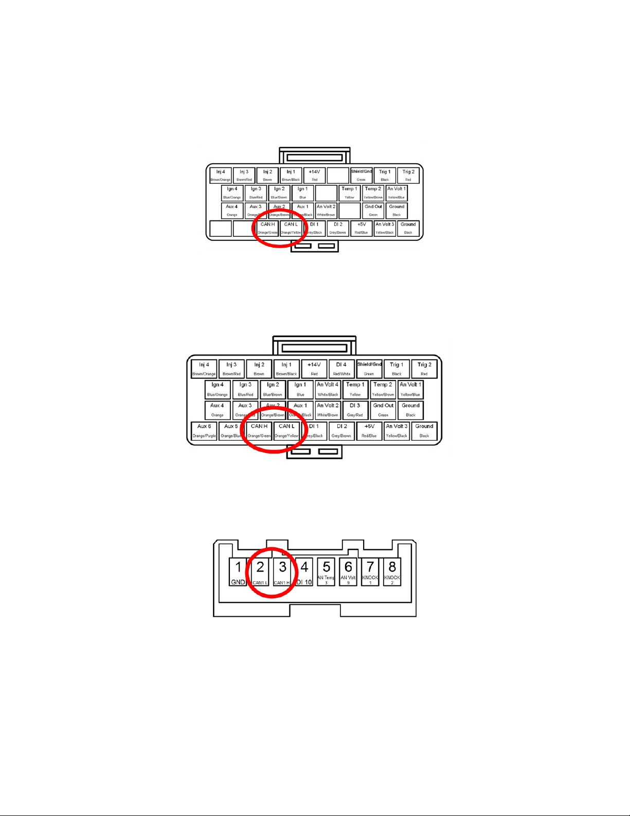
1.1.1 Atom Header pinout: ............................................................................................................6
1.1.2 Monsoon Header Pinout:......................................................................................................6
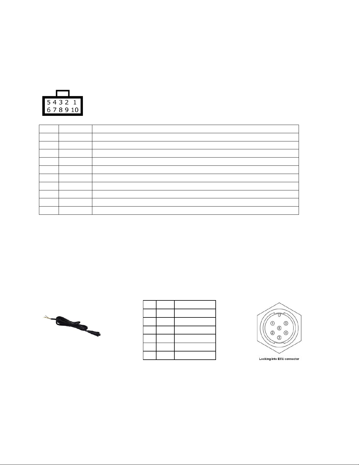
1.1.3 Kurofune Header Pinout .......................................................................................................6
2 Menus and buttons...............................................................................................................................7
2.1 Real-Time Display Screens ............................................................................................................7
2.2 Settings..........................................................................................................................................7
2.2.1 Screen Brightness..................................................................................................................7
2.2.2 LED Brightness.......................................................................................................................7
2.2.3 Units......................................................................................................................................7
2.2.4 Input Configuration...............................................................................................................7
2.2.5 Wi-Fi hotspot.........................................................................................................................7
2.2.6 Safe Mode.............................................................................................................................8
2.2.7 Edit text color........................................................................................................................8
2.2.8 Disable / Enable screen designer..........................................................................................8
2.2.9 Select boot mode..................................................................................................................8
2.2.10 Select ECU Model..................................................................................................................8
2.2.11 General Info ..........................................................................................................................8
2.2.12 Factory Reset.........................................................................................................................8
3 CAN Bus.................................................................................................................................................9
3.1 CAN bus resistor............................................................................................................................9
3.2 Display values from ECU over CAN bus.........................................................................................9
3.2.1 Link G4+ and Vi-PEC i44 or i88 ECU configuration..............................................................10
3.2.2 With Link G4 or Vi-PEC v44, v88..........................................................................................10
3.2.3 Custom values with Link G4 (requires gauge firmware version 60 and up). ......................11
4 WiFi .....................................................................................................................................................13
4.1 How to connect and access the gauge configuration webpage .................................................13

www.PerfectTuning.net 3 November 2017
4.2 Help.............................................................................................................................................13
4.3 Web pages...................................................................................................................................13
4.3.1 Home...................................................................................................................................13
4.3.2 Config. .................................................................................................................................14
4.3.3 Inputs ..................................................................................................................................14
4.3.4 Alarms .................................................................................................................................15
4.3.5 Upgrade...............................................................................................................................16
4.3.6 Admin..................................................................................................................................17
5 Alarms .................................................................................................................................................17
6 Accessories and Sensors......................................................................................................................19
6.1 Perfect Tuning Wideband controller: .........................................................................................19
6.1.1 Calibration procedure.........................................................................................................19
6.2 EGT..............................................................................................................................................19
6.3 Oil pressure sensor .....................................................................................................................20
6.4 Oil, coolant and air temperature sensor.....................................................................................20
6.5 Map sensors................................................................................................................................21
6.5.1 GM 3 bar map sensor..........................................................................................................21
6.6 12v Buzzer...................................................................................................................................22
7 12 Month Limited Warranty ...............................................................................................................22
8 Dimensions..........................................................................................................................................23
9 Contact................................................................................................................................................23
10 Compatible accessories:......................................................................................................................23

www.PerfectTuning.net 4 November 2017
Warning
All parts are sold for OFF ROAD RACE-ONLY ground-vehicle use only.
Keep your eyes on the road when using this product.
Race parts are inherently dangerous and may cause injury or damage if improperly modified or altered
before use. Perfect Tuning will not be held liable for and will not pay you for any injuries or damage
caused by misuse, modification, redesign, or alternation of any of our products. Perfect Tuning will not
be held in any way responsible for any incidental or consequential damages including direct or indirect
labour, towing, lodging, garage, repair, medical, or legal expense in any way attributable to the use of
any item in our catalogue or to the delay or inconvenience caused by the necessity of replacing or
repairing any such item.
The gauge is not waterproof or water resistant. Avoid putting water over it, on the screen and on the
LEDs.
If you’re not sure how to install and connect the gauge after reading this user manual, contact a
competent shop to do the installation.
Do not use longer screw than provided in the two rear mounting holes. Using too long screws can touch
the circuit board inside and damage the gauge.
Introduction
Thank you for your purchase. The customer satisfaction at Perfect Tuning is our biggest priority. If you
have any questions, suggestions or issues do not hesitate to contact us at support@perfecttuning.net or
on Facebook.
The Perfect Tuning Universal Gauge is a good alternative to expensive race dashes or bigger displays. It's
a way more than a simple gauge with the possibility to connect up to 3 sensors directly to the gauge and
by having the possibility to display values from an aftermarket ECU at the same time!
The alarm module is a very nice feature that allows the user to monitor what he wants and never miss
an abnormal condition.
Please note that the gauge will fit in a 52 mm pod but keep in mind that the overall dimensions are 69
mm so it might not fit well in a multiple gauge pod where all the gauges are very near each other.
Follow us on Facebook or subscribe to our YouTube channel to be aware of all the software upgrades
including all the latest features and newest products.

www.PerfectTuning.net 5 November 2017
1Wiring
Always disconnect the vehicle battery when installing the gauge. Do not leave any wires not isolated.
Always solder or crimp the wires and protect with heat shrink. Refer to the user manual to connect the
sensors.
View when looking at the gauge.
Pin
Color
Function
1
Red
12v ( + ). Always install the gauge on a fused supply (3A)
2
Black
Vehicle Ground (- )
3
White
0-5v analog input 1 (optional)
4
Yellow
0-5v analog input 2 (optional)
5
Brown
CAN bus H
6
Purple
CAN bus L
7
Orange
0-5v analog input 3 (optional)
8
Gray
Digital input (not available)
9
Blue
5v output (optional)
10
Green
Digital output. Connected to the ground when output is enabled.
1.1 Connection to the Link G4+ or Vi-PEC
Always refer to the user manual and locate the CAN High (CANH) and CAN Low (CANL) pins.
Link G4+ Thunder, Xtreme, Fury, Storm (Black) wire-in ECUs have a communication port on the front
plate of the ECU directly below the tuning port. The following is the pin information for the
communication port.
The Cable (CANDASH) part number 101-0019 is required or the lug (CANF) part number 101-0020.
Pin
Colour
Function
1
Brown
Ground
2
Blue
NC
3
White
CAN H
4
Green
CAN L
5
Yellow
ECU RS232 TX
6
Gray
ECU RS232 RX
Note: Link G4+ Atom, Monsoon and Kurofune wire-in ECUs do not have a communication port. They do
however have CAN bus pins on their respective connctors: Atom, Monsoon and Kurofune.

www.PerfectTuning.net 6 November 2017
1.1.1 Atom Header pinout:
Viewed looking into ECU header (or wire side of loom connector)
1.1.2 Monsoon Header Pinout:
Viewed looking into ECU header (or wire side of loom connector)
1.1.3 Kurofune Header Pinout
Pins labeled J[1..8] are found on the JST connector on the rear of the ECU.

www.PerfectTuning.net 7 November 2017
2Menus and buttons
There are two buttons to navigate through the different menus of the gauge and edit basic settings.
Press left to move to the left or to go up and press the right button to move to the right or go down.
Press both buttons to select or enter. It’s not possible to go back. If you entered a menu by error, press
both buttons until you’re back to the previous screen or power off the gauge.
2.1 Real-Time Display Screens
Almost the real time screens are configurable. First, validate that “Screen designer” is enabled in the
Settings menu. Then where a value is displayed, press both buttons to open the screen designer. A
rectangle will appear around the value that is selected. Press both buttons to edit this value and a list of
inputs will appear. Select the desired value with left and right button and press both to select the value.
2.2 Settings
This section will describe each configuration screen.
2.2.1 Screen Brightness
Use this menu to change the screen brightness intensity.
2.2.2 LED Brightness
Use this menu to enable or disable automatic light adjustment. It’s possible to specify the led intensity
during day and night. Depending on the LEDs intensity, light can be reflected into the light sensor. If you
have this issue, it’s suggested to disable the automatic dimming of the LEDs.
2.2.3 Units
This screen is used to select the displayed units for different values on the screen. Do not mix up
pressure and MAP. Units are different.
2.2.4 Input Configuration
Configure the three 0-5v analog inputs by selecting which input to configure, and then select the sensor.
For advanced or custom configuration, see the Wi-Fi section.
2.2.5 Wi-Fi hotspot
Advanced configuration of the gauge is made over the configuration web page. Press both buttons to
enable the Wi-Fi hotspot. This will create a Wi-Fi network named PerfectTuning-XXXX (where XXXX will
vary on every gauge). The hotspot is not password protected and this is why it cannot be left always
active. Leaving this screen will disable the hotspot. Once connected to the PerfectTuning-XXXX hotspot,
open a web navigator (Google Chrome is recommended) and navigate to the address 192.168.0.1. This
will bring the configuration webpage. See the Wi-Fi section for more information.

www.PerfectTuning.net 8 November 2017
2.2.6 Safe Mode
Safe mode is for firmware upgrade recovery in case of problems. Safe mode can also be accessed by
pressing both buttons while powering the gauge.
2.2.7 Edit text color
Change the text color in the menus and in few real-time display values.
2.2.8 Disable / Enable screen designer
The screen designer is used to select which value is displayed in the real time screens. To prevent editing
these values, disable the screen designer.
2.2.9 Select boot mode
There are eleven different boot sequences that are available to execute when the gauge is powered up.
The number 11 is no boot sequence.
2.2.10 Select ECU Model
Select between older link G4, v44 and v88 or G4+, i44 and i88. This will change few parameters. The
gauge will reboot after the selection.
2.2.11 General Info
This menu display general gauge information like hardware version, software version and serial number
that can be useful for support.
2.2.12 Factory Reset
Reset all settings to factory default.

www.PerfectTuning.net 9 November 2017
3CAN Bus
The gauge can display values coming from the aftermarket ECU over the CAN bus
3.1 CAN bus resistor
On the back of the gauge, there is a jumper for the 120 ohms end of bus resistor next to the cable
connector. To disconnect the 120 ohms resistor, remove the jumper. Unless there is more than 1 device
connected to the CAN bus, leave the jumper installed.
3.2 Display values from ECU over CAN bus
All this information is available on all models
Value
Description
RPM
Engine rotation speed
MAP (kpa)
Manifold air pressure in KPA
MAP (PSI)
Manifold air pressure in PSI
MGP
Manifold pressure gauge
Baro
Barometer reading
TPS
Throttle position
DUTY
Injector duty cycle
DUTY2
Injector (secondaries) duty cycle
ECT
Coolant temperature (C or F)
IAT
Intake temperature (C or F)
Batt V.
Battery voltage at the ECU. Different than Batt which is voltage
at the gauge.
MAF
Mass air flow
Gear
Transmission gear
INJT
Injector timing
Ign. Adv.
Ignition advance
CINL
Cam Inlet Position L
CINR
Cam Inlet Position R
CEXL
Cam Exhaust Position L
CEXR
Cam Exhaust Position R
AFR1
Air/fuel ratio 1 (Lambda or AFR)
AFR2
Air/fuel ratio 1 (Lambda or AFR)
CODE
ECU error code
FP
Fuel Pressure (kPa, Bar or PSI)
OILT
Oil temperature (C or F)
OILP
Oil Pressure (kPa, Bar or PSI)
AFRT
Air/fuel ratio target (Lambda or AFR)
FL
Wheel speed front left
FR
Wheel speed front right
RL
Wheel speed rear left
RR
Wheel speed rear right
KNK1-8
Knock retard per cylinder
See section

www.PerfectTuning.net 10 November 2017
3.2.1 Link G4+ and Vi-PEC i44 or i88 ECU configuration
Connect to you ECU using PCLink or iVTS software and go to ECU Controls, CAN Setup. Set the Mode to
user defined, bit rate to 1 Mbit/s. Select channel 1 and select Transmit Generic Dash with transmit rate
of 20 Hz. Set the CAN ID to 1000 with Normal format checked.
3.2.2 With Link G4 or Vi-PEC v44, v88
Be aware that there is a problem with the can bus on the G4 ecu only with serial number under 10 000.
Contact your dealer for more details.
Connect to you ecu using PClink or VTS software and go to ECU Controls, CAN Setup. Set the Mode to
user defined, bit rate to 1 MBPS. Select channel 1 and click on load. Select Generic Dash with transmit
rate of 20 Hz. Set the CAN ID to 1000.

www.PerfectTuning.net 11 November 2017
3.2.3 Custom values with Link G4 (requires gauge firmware version 60 and up).
To display values that are not available on the “Generic Dash” stream, a custom stream is required. At
this moment, only fuel content and temperature is available but if any other value is required, please
contact us by email at support@perfecttuning.net and we’ll add it in the next firmware version of the
gauge.
Start by adding a custom transmit user stream on channel 2 with ID of 1100. Transmit rate can be set to
10 Hz.

www.PerfectTuning.net 12 November 2017
Then go to the “Streams” tab and add Frame 1 to Stream 1.
Set “ID Position”to 0 and ID to 0.
Add a parameter and select % Ethanol from the Fuel section. Start Pos: 8, Width: 8, MS First:
Unsigned, Multiplier: 1, Divider: 1, Offset: 0.
Add second parameter Ethanol Temp. from the Fuel section. Start Pos: 16, Width: 8, MS First:
Unsigned, Multiplier: 1, Divider: 1, Offset: -50.
Press apply and you’re good to go!

www.PerfectTuning.net 13 November 2017
4WiFi
4.1 How to connect and access the gauge configuration webpage
The gauge can be configured with any recent smartphone, tablet or laptop that is able to browse a
webpage. Only one connection at the same time is supported.
First, go to “Settings”on the gauge, and enable the “Wi-Fi hotspot”.
Connect to the PerfectTuning-XXXX WiFi hotspot on your device.
Open the browser used to navigate the internet and type 192.168.0.1
Google Chrome web browser is recommended and only one connection is supported.
The home web page will appear.
In rare occasion, it’s possible that some device have trouble connecting to the hotspot. Specifying a fixed
IP of 192.168.0.2 might help or try rebooting the gauge.
4.2 Help
Click on the question mark logo in the web pages for more information about each option.
4.3 Web pages
4.3.1 Home
The home page display information related to the gauge like the serial number, software version,
hardware version, html version, JavaScript version and system version.

www.PerfectTuning.net 14 November 2017
4.3.2 Config.
The configuration page allows changing general settings of the gauge like units, LED ring intensity and
more. The color tool is not available on IOS devices like iPhones and iPads. IOS users must enter the text
color value in hexadecimal.
Always hit “Save Settings”before going to another page.
4.3.3 Inputs
The input page allows editing the analog input configuration. It is possible to select between the
different supported sensors or enter custom values for a different sensor. Custom thermistor tables are
not supported.
Smoothing is important. The default value is 100. 100 mean no smoothing. 15 mean maximum
smoothing. Change this setting to smooth or increase response of the analog inputs.
Always hit ”Save Settings”before configuring next input.

www.PerfectTuning.net 15 November 2017
4.3.4 Alarms
This page is used to configure up to 16 alarms on the gauge. Each alarm can contain 2 conditions. Each
field is explained by clicking on the question mark logo .
Alarms with a smaller number have higher priority.
Always hit “Save Settings”before configuring next alarm.

www.PerfectTuning.net 16 November 2017
4.3.5 Upgrade
1. Download the latest firmware upgrade file suited for your gauge (please verify your serial
number) and select model required at http://perfecttuning.net under the support tab.
2. The firmware upgrade can be done with a smartphone, laptop or a tablet running Windows,
Android or IOS.
3. Power up the gauge, go to settings, Wifi hotspot and enable it by pressing both buttons.
4. On your laptop or smartphone and connect to the new wifi hotspot named PerfectTuning-XXXX.
5. Firefox browser is not supported. Use Google Chrome to do the firmware upgrade. On IOS
devices, this is tricky because the IOS devices cannot store a .bin file easily; the user must save
the firmware file to iCloud first. And then select the file from there in Safari.
6. Open your browser and navigate to http://192.168.0.1
7. Click on the Upgrade tab.
*** WARNING *** for all the gauges running firmware version under 22, contact us to get a
firmware upgrade file. The files on the website won’t work with your gauge ***
8. Click on browse to select the ptugxxxxxxxxx.bin file suited for your gauge.
9. Click on “Begin upgrade”. The upgrade should take less than 30 seconds.
10. Accept the pop-up and don’t do anything else. Wait until an other message appears and check
the gauge for any messages or a gauge reboot.
11. After the reboot, on the gauge, go to settings, general info and validate that the “sw version” is
the same as the file you used for the upgrade. If not, try again.
For all the gauges that are running the software version under 44, an upgrade of the HTML files is
required too.
After upgrading to the latest version, enable wifi and navigate to the web page. Then instead of
upgrading the bin file, select the file named rescueUpgrade.html. Do not send it if you're not on
firmware 45 or over. When it's done. go to 192.168.0.1/rescueUpgrade.html. If the page load, then
send select, index.html and press begin upgrade again.
IT IS VERY IMPORTANT TO FOLLOW ALL THE STEPS IN ORDER TO DO YOUR FIRMWARE UPGRADE
CORRECTLY. NOT FOLLOWING THE STEPS HERE CAN BRICK YOUR GAUGE.
Optional: This page can also be used to change the boot logo image.
There is no support regarding changing the boot image and if there is any problem related to this, this
won’t be covered under the warranty.
Create a .bmp file with 24 bits color depth in paint with a dimension of 160x128 pixels. Name this file
boot.bmp and use the upgrade tab to upload the file to the gauge.

www.PerfectTuning.net 17 November 2017
4.3.6 Admin
The admin page is used to do a factory reset of the gauge.
The WiFi credentials section is for support and advanced users only. These settings are not related to
the Wi-Fi hotspot SSID and password so do not try to change this.
5Alarms
The alarms are not configurable directly on the gauge. See the Wi-Fi section of the user manual to
understand how to connect to the web interface of the gauge and configure the alarms.
An alarm can be ignored by pressing any button. Pressing both buttons when an alarm is active will
disable the alarm until next reboot.
Alarms are only displayed when the real time screens are active. The alarms won’t be generated if the
gauge is in the settings menu.
In each alarm configuration, it’s possible to set a custom name.
Then select on which channel this alarm will be set. Select a condition (< Smaller, > Bigger, = Equal), a
threshold value and a hysteresis value.
Second condition is use to make combination of condition to generate an alarm. The condition “AND”
(condition 1 AND condition 2 must be active for the alarm to be generated) or “Or” (condition 1 or
condition 2 must be active to generate the alarm) can be selected.
A begin and ending delay can be specified in seconds.
Select the LED ring mode (fast blink, slow blink, solid, off) and LED ring color.
The output to ground check box can be used to ground the digital output when the alarm is active.

www.PerfectTuning.net 18 November 2017
Require Ack is used to leave the alarm active as long as the user doesn’t acknowledge the alarm by
pressing a button on the gauge.
Eg: Channel is MAP (PSI). Condition is bigger, threshold is set to 20 and hysteresis is set to 1. Begin delay
is set to 1 and end delay is set to 0.
When the MAP value will go over 20 psi for at least 1 second the alarm will be generated. Because there
is a hysteresis value set to 1. The value must go under 19 psi for 0 seconds for the alarm to end. When
the alarm is active, the LED ring will blink in red quickly. As soon as the value is under 19 psi, the gauge
will display the previous real time screen.

www.PerfectTuning.net 19 November 2017
6Accessories and Sensors
6.1 Perfect Tuning Wideband controller:
Wires color of the Perfect Tuning wideband controller.
Color
Function
Red
12v with 5A fuse.
White
Power ground. Connect to the same ground of the gauge.
Black
Sensor ground. Connect to the same ground of the gauge.
Green
0-5v linear output connected to any analog inputs of the gauge.
Orange
Narrowband output is unused
Blue
Led output for the heater is unused.
6.1.1 Calibration procedure
When the wideband sensor is selected in the Inputs configuration menu, a reboot will be required for
calibration. This will work only with the Perfect Tuning wideband controller. To cancel this calibration,
press both buttons during the calibration sequence.
6.2 EGT
Power the EGT-K controller VCC pin to 12v and GND to ground. Connect the OUT1 to any analog input
of the gauge (white, yellow or pink wire) and the output GND to the black wire of the gauge.
Connect the EGT probe black wire to the TC1- pin and red wire to TC1+.

www.PerfectTuning.net 20 November 2017
6.3 Oil pressure sensor
The oil pressure sensor is compatible with oil, fuel, water or air pressure.
Accuracy: within 1.5% of reading (full scale).
Thread: 1/8”-27 NPT.
Wiring connector: water sealed quick disconnect. Mating connector and wire harness (pigtail) are
included.
Red
5v (blue wire of the gauge)
Black
Ground (black wire of the gauge)
Blue
Signal (white, yellow or pink wire of the gauge).
6.4 Oil, coolant and air temperature sensor
Thermistors must be connected with a 1k provided pull up resistor to 5v and grounded at the same
place where the gauge is grounded.
Resistor is connected to the blue wire of the gauge (5v output) and the other side is connected to any
input (white, yellow or pink wire). Thermistor is connected to the same analog input and the other pin
to the black wire of the gauge. The polarity of the resistor and thermistor is not important.
Table of contents
Other Perfect Tuning Automobile Electronic manuals
Popular Automobile Electronic manuals by other brands

JastecM
JastecM JLM1-2000 manual

Audiovox
Audiovox CMOS2 instruction manual

JVC
JVC KD-AVX77 - EXAD - DVD Player Installation & connection manual

Audiovox
Audiovox A-ACC-BMW-DSP Install supplement

Dynojet
Dynojet Power commander V installation instructions

Audiovox
Audiovox CarStream Installation guide & user manual