PerfectVision PV-HD26226 Guide

V4.7-CPatent # US 8,424,638
OPERATION AND INSTRUCTION MANUAL
Swivel Anchor Model: PV-HD26226
WARNING:
ALL PERSONS USING THIS EQUIPMENT MUST
READ AND UNDERSTAND ALL INSTRUCTIONS. FAILURE TO DO
SO MAY RESULT IN SERIOUS INJURY OR DEATH. USERS SHOULD
BE FAMILIAR WITH PERTINENT REGULATIONS GOVERNING THIS
EQUIPMENT. ALL INDIVIDUALS WHO USE THIS PRODUCT MUST
BE PROPERLY INSTRUCTED ON HOW TO USE THE DEVICE. AVOID
CONTACT WITH PHYSICAL HAZARDS (THERMAL, CHEMICAL,
ELECTRICAL, ETC.). MAKE ONLY COMPATIBLE CONNECTIONS.

User Instructions must always be available to the user and are not to be removed except by the user of this equipment. For proper
use, see supervisor, User Instructions, or contact the manufacturer.
Compliant fall protection and emergency rescue systems help prevent serious injury during fall arrest. Users and purchasers of
this equipment must read and understand the User Instructions provided for correct use and care of this product. All users of this
equipment must understand the instructions, operation, limitations and consequences of improper use of this equipment and be
properly trained prior to use per OSHA 29 CFR 1910.66 and 1926.503 or applicable local standards.
Misuse or failure to follow warnings and instructions may result in serious personal injury or death.
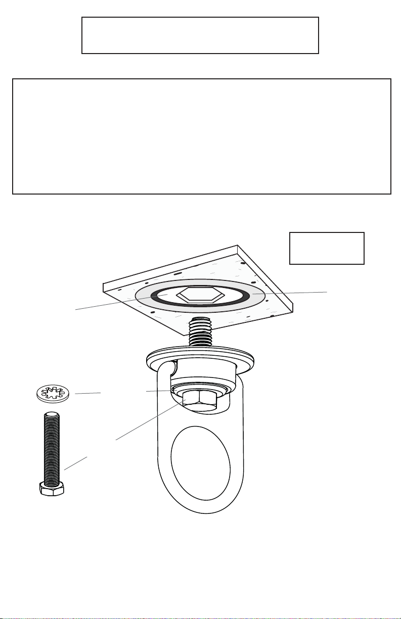
PURPOSE
The PV-HD26226 is an anchorage connector designed to function as an interface between the anchorage and a fall protection, work
positioning, rope access, or rescue system for the purpose of coupling the system to the anchorage. Any references to “anchorage
connector” in this manual include, and apply to, the PV-HD26226.
USE INSTRUCTIONS
1. A user must be of sound mind and body to properly and safely use this equipment in normal and emergency
situations. Users must have a physician ensure they are clear of any medical conditions that may aect the proper
and safe use of this equipment in normal and emergency situations.
2. Before using a personal fall arrest system, user must be trained in accordance with the requirements of OSHA 29
CFR 1910.66 in the safe use of the system and its components.
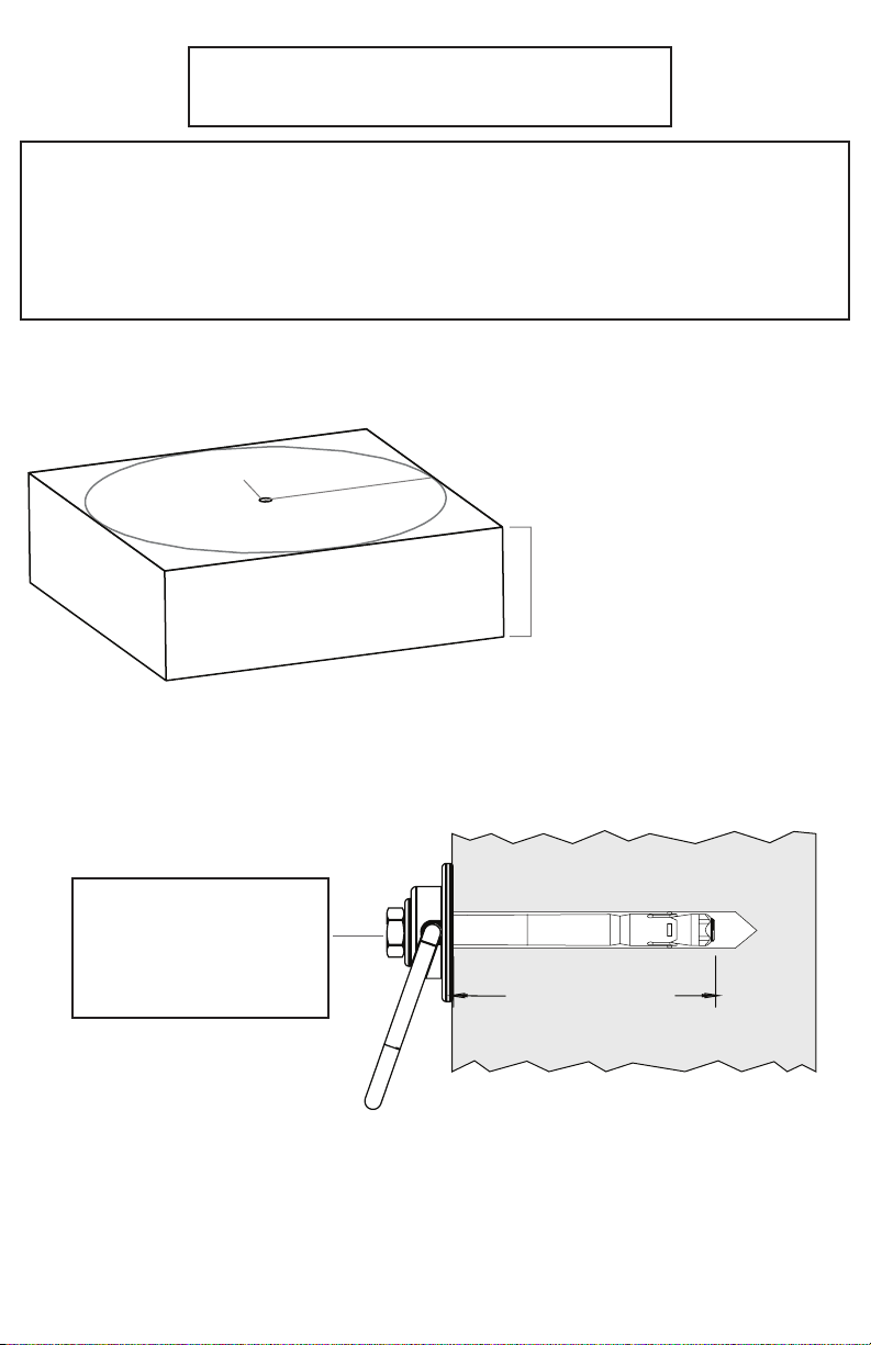
3. Use only with ANSI/OSHA compliant personal fall arrest or restraint systems. The anchorage must have the
strength capable of supporting a static load, applied in the directions permitted by the
system, of at least 10,000-lbf (44kN) in the absence of certication.
4. The user shall be equipped with a means of limiting the maximum dynamic forces exerted on the user during the
arrest of a fall to a maximum of 8 kN (1800-lbf). In the EU these forces must be limited to 6 kN (1350-lbf.)
5. Use of this product must be approved by an engineer or other qualied person to be compatible with any and
all structural & operational characteristics of the selected installation location and system to be connected to this
anchorage connector.
6. The anchorage connector must be inspected prior to each use for wear, damage, and other deterioration. If
defective components are found the anchorage connector must be immediately removed from service in
accordance with the requirements of OSHA 29 CFR 1910.66 and 1926.502.
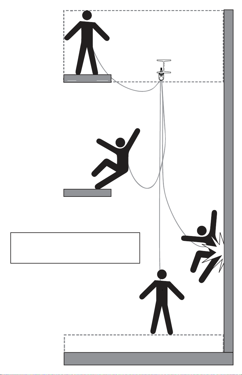
7. The anchorage connector should be positioned in such a way that minimizes the potential for falls and the
potential fall distance during use. The complete fall protection system must be planned (including all components,
calculating fall clearance, and swing fall) before using.
8. A rescue plan, and the means at hand to implement it, must be in place that provides the prompt rescue of users
in the event of a fall, or assures that users are able to rescue themselves.
9. After a fall occurs the anchorage connector must be removed from service and destroyed immediately.
USE LIMITATIONS: The anchorage connector shall not be used outside its limitations, or for any purpose other than that
for which it is intended.
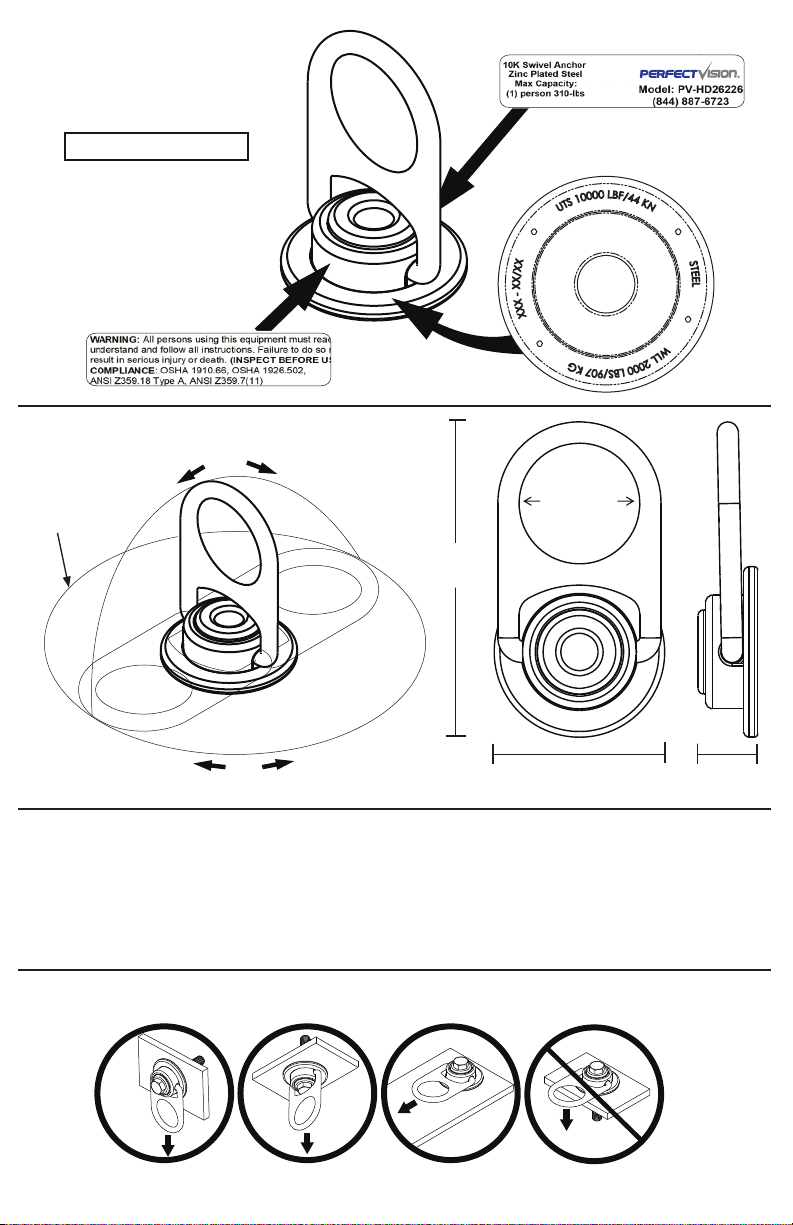
1. The anchorage connector is designed for single user, with a capacity up to 310 lbs (140 kg) including
clothing, tools, etc.
2. The anchorage connector may only be loaded in acceptable directions shown in the LOADING CONDITIONS
DIAGRAM.
3. The anchorage connector is designed to be used in temperatures ranging from -40ºF to +130ºF (-40°C to +54°C).
4. Do not expose the anchorage connector to chemicals or harsh solutions which may have a harmful eect.
5. Do not alter or modify this product in any way.
6. Caution must be taken when using any component of a fall protection, work positioning, rope access, or rescue
system near moving machinery, electrical hazards, sharp edges, or abrasive surfaces, as contact may cause
equipment failure, personal injury, or death.
7. Do not use/install equipment without proper training by a“competent person”as defined by OSHA 29
CFR 1926.32(f).
8. Do not remove the labeling from this product.
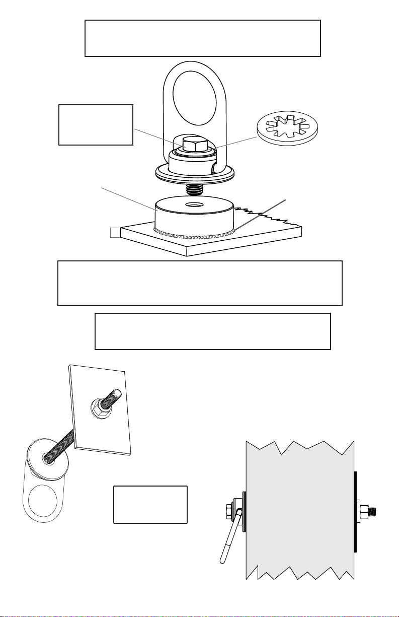
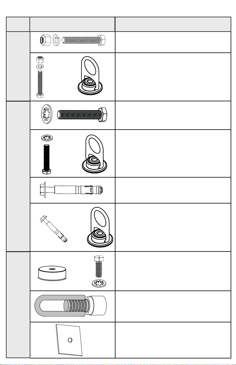
9. Additional requirements and limitations may apply depending on anchorage type and fastening option utilized
for installation. All placements must be approved by an engineer or other qualied person.
10. This anchorage connector should not be used as part of a horizontal lifeline system that has not been designed
and or approved to be used with 10,000-lbf anchorage connectors.
11. The anchorage connector should only be used for personal fall protection and not for lifting equipment.
COMPATIBILITY LIMITATIONS
Anchorage connector must only be coupled to compatible connectors. OSHA 29 CFR 1926.502 prohibits snaphooks from being
engaged to certain objects unless two requirements are met: it must be a locking type snaphook, and it must be “designed for”
making such a connection. “Designed for” means that the manufacturer of the snaphook specifically designed the snaphook to be
used to connect to the equipment listed. The following connections must be avoided, because they can result in rollout* when a
nonlocking snaphook is used:
• Direct connection of a snaphook to horizontal lifeline.
• Two (or more) snaphooks connected to one D-ring.
• Two snaphooks connected to each other.
• A snaphook connected back on its integral lanyard.
• A snaphook connected to a webbing loop or webbing lanyard.
• Improper dimensions of the D-ring, rebar, or other connection point in relation to the snaphook dimensions that
would allow the snaphook keeper to be depressed by a turning motion of the snaphook.
*Rollout: A process by which a snaphook or carabiner unintentionally disengages from another connector or object
to which it is coupled. (ANSI Z359.0-2007)
Read This Instruction Manual Carefully Before Using This Equipment.

LOAD LOAD LOAD
LOAD
LABEL LOCATIONS
8”ø
(203.2mm)
180°
360°
5.5”
(139.7mm)
2.25”ø
(57.15mm)
3”
(76.2mm)
1”
(25.4mm)
Tensile Strength (UTS): 10,000-lbf (44kN)
Working Load: 2,000-lbs (907kg)
Weight: 1.2-lbs (544.3g)
Materials: Zinc Plated Steel
Regulatory Compliance: Meets or exceeds ANSI Z359.18 Type A, ANSI Z359.7-2011
OSHA 1926.502, OSHA 1910.66
LOADING CONDITIONS DIAGRAM
ACCEPTABLE ACCEPTABLE IMPROPER
ACCEPTABLE

STEEL MOUNTING
Torque Range:
75 to 90 ft-lbs
(100-120Nm)
* Use tapered washer with I-beams
that have tapered anges.
.75”
(6mm)
min
drill 5/8” (16mm)Ø
3”(76mm)
min from any edge
Lock Nut
5/8” Lock
Washer
5/8”-11x4”
Hex Bolt *
5/8”-11
* For steel applications a grade 5, grade 8 (or equivalent) bolt no
shorter than 4” (100mm) with a locking nut and washer must be
used. Swivel anchor must be ush with steel surface. A 16mm
bolt of equal strength may be used in place of a 5/8”-11
for metric applications.
1. Use a proper drill and bit for steel.
2. Drill a 5/8” (16mm) hole no less than .75” (6mm) deep 3” (76mm) away from any edge.
3. Hole must be straight and perpendicular to surface.
4. Hole must be free of debris.

CONCRETE MOUNTING
1. Use a proper drill and bit for concrete (SDS drill bit).
2. Drill a .75” (19mm) hole no less than 5” (114mm) deep 9” (229mm) away from any edge.
3. Hole must be straight & perpendicular to surface.
4. Hole must be free of debris
5. Concrete strength must be at least 3000psi (20.7MPa) and no less than 7” (178mm)
thick.
9” (229mm)
drill 3/4” (19mm)Ø
min from any edge
7”
(178mm)
min
Embedment Depth
4.5” min (114mm)
Torque:
110 ft-lbs (149Nm)

BACK PLATE MOUNTING
WELD ON MOUNTING
* Welding procedure must be approved by an engineer or other
qualied person to be compatible with any and all structural &
operational characteristics of the selected installation location.
Torque Range:
to be determined
by an engineer or
qualied person.
Back Plate to be used with 5/8”(16mm)
bolts or all thread. Drill hole perpendicular
into surface so bolt can pass freely through
the substrate. Nut must be fully threaded
on the bolt to insure maximum strength
ratings and integrity of anchor.
* Bolt or All-thread and nut not included with Back Plate.
Torque Range:
75 to 90 ft-lbs
(100-120Nm)
Grade - 5 or 8 bolt
5/8”-11 x 1-3/4”
Weld Puck
(AISI 1018)
3/8” min
(9.5mm)
* Weld
Internal Tooth Lock Washer

STRAIGHT LOOP INSERT
See Straight Loop Insert Manual for anchorage casting instructions.
Internal Tooth
Lock Washer
WARNING: Do not install if insert was knocked over during installation.
Mega Swivel must mount ush to surface when fastened with the
proper torque.
Torque Range:
70 to 80 ft-lbs
Orange
Housing
Plastic Bolt to
be removed
5/8”-11x3.25”
Hex Cap Bolt *
Note: Ensure internal threads are
thoroughly coated with NLGI2
multi-purpose lithium grease
(meeting Sinopec specication
Q/SH303 242-2007 or equivalent).
1. Strip decking to expose the Straight Loop Insert.
2. Ensure that anchorage was properly installed. Orange indicator should be ush with
concrete surface, and at least 9”from any edge or corner. Concrete should be at least
6” thick and cured to a minimum of 3000 psi.
3. Remove plastic bolt and o-ring using 1/2” allen wrench.
4. Save plastic bolt and o-ring to re-insert into Straight Loop Insert when not in use.
5. Insert bolt and washer through Mega Swivel and into the threaded
hole of the Straight Loop Insert.
6. To fasten Mega Swivel, tighten bolt* to 70-80 ft-lbs using torque wrench.

WORK SURFACE
WORK SURFACE
*All products subjected to fall arresting
forces should be removed from service
immediately!
(ANCHOR POINT)
*The structure the
anchorage is attached
to must be able to
support 10,000-lbf
(44kN) and installed
under the supervision
of a qualied person.
MINIMUM CLEARANCE 3ft (1m)
DECK/FLOOR/GROUND LEVEL
WARNING!!! SWING FALLS MAY OCCUR WHEN THE WORKER IS NOT DIRECTLY UNDER ANCHOR POINT.
*The user shall be equipped with a means of
limiting the maximum dynamic forces exerted
on the user during the arrest of a fall to a
maximum of 8 kN (1800-lbf). In the EU these
forces must be limited to 6 kN (1350-lbf.)

+
CONCRETE METALACCESSORIES
KIT CONTENTS PART NUMBER
+
Call for more info.
(Steel Mounting Hardware Kit)
PV-HD26226
(Swivel with Steel Mounting kit)
Call for more info.
(Concrete Hardware Kit)
Call for more info.
(Swivel with Concrete Mounting Kit)
Call for more info.
(Weld-on Mounting Kit)
Call for more info.
(Backing Plate Only)
+
Call for more info.
(Swivel with Straight Loop Insert
Mounting kit)
Call for more info.
(Straight Loop Insert Mounting Kit)
+
Call for more info.
(Straight Loop Insert)

Part Number Comments Inspector Name
Date
MODEL NUMBER:
DATE OF MANUFACTURE:
MAINTENANCE, CLEANING AND STORAGE
Cleaning periodically will prolong the life and proper functioning of the product. The frequency
of cleaning should be determined by inspection and by severity of the environment. Clean with
compressed air and/or a sti brush using plain water or a mild soap and water solution. Do not use
any corrosive chemicals that could damage the product. Wipe all surfaces with a clean, dry cloth
and hang to dry, or use compressed air. When not in use, store anchorage connectors in a cool, dry,
clean environment, out of direct sunlight and free of corrosive or other degrading elements.
INSPECTION AND MAINTENANCE LOG
Inspection:
A. Product shall be inspected by a competent person prior to each use.
B. Official periodic inspection must be made alongside the structure's TIA-222 Annex J maintenance and
condition assessment schedule. The inspection must be performed by a qualified person other than the
intended user.
1. Inspect swivel to make sure it is ush with mounting surface.
2. Make sure all labeling is axed to the unit.
3. Make sure the unit can rotate 360° and D-ring can ip from side to side.
4. When reusing a previously drilled hole, inspect for for debris or wallowing.
5. Inspection results may be recorded in the space provided above.
*If any damage that could aect the strength or operation of the device, or unsafe condi-
tions are found, proper disposal is required. The anchorage connector must be rendered
unusable and then properly discarded.

NOTES

PerfectVision
16101 La Grande Drive | Little Rock, AR 72223
844.887.6723 | www.perfect-vision.com
Product Warranty, Limited Remedy and Limitation of Liability
WARRANTY: THE FOLLOWING IS MADE IN LIEU OF ALL WARRANTIES OR CONDITIONS, EXPRESS OR
IMPLIED, INCLUDING THE IMPLIED WARRANTIES OR CONDITIONS OF MERCHANTABILITY OR FITNESS
FOR A PARTICULAR PURPOSE.
LIMITED REMEDY: Upon notice in writing, PerfectVision will repair or replace all defective items at Perfect
Vision’s sole discretion. PerfectVision reserves the right to require that the defective item be returned to its
plant for inspection before determining the appropriate course action. Warranty does not cover equipment
damage resulting from wear, abuse, damage in transit, failure to maintain the product or other damage
beyond the control of PerfectVision. PerfectVision shall be the sole judge of product condition and warranty
options. This warranty applies only to original purchaser and is the only warranty applicable to this product.
Please contact PerfectVision technical service department for assistance.
LIMITATION OF LIABILITY: IN NO EVENT WILL PERFECTVISION BE LIABLE FOR ANY INDIRECT,
INCIDENTAL, SPECIAL OR CONSEQUENTIAL DAMAGES INCLUDING, BUT NOT LIMITED TO LOSS OF
PROFITS, IN ANY WAY RELATED TO THE PRODUCTS REGARDLESS OF THE LEGAL THEORY ASSERTED.
Table of contents