manuals.online logo
Brands
  1. Home
  2. •
  3. Brands
  4. •
  5. Performance Tool
  6. •
  7. Paint Sprayer
  8. •
  9. Performance Tool M715 User manual

Performance Tool M715 User manual

WARNING!
READ, UNDERSTAND AND FOLLOW ALL INSTRUCTIONS AND
WARNINGS BEFORE OPERATING THIS TOOL. FAILURE TO DO SO
MAY RESULT IN PERSONAL INJURY AND/OR PROPERTY DAMAGE AND
WILL VOID WARRANTY.
1 YEAR WARRANTY
PERFORMANCE TOOL® extends only the following warranties, and only to original retail purchasers. These
warranties give specific legal rights. Except where prohibited by local law, the law of the State of Washington
governs all warranties and all exclusions and limitations of warranties and remedies. There may be other rights
which vary from state to state.
PERFORMANCE TOOL® warrants the product to be free from defects in materials and workmanship under normal
use and service. A defective product may be returned for a free replacement within 90 days from the date of
purchase, provided that product is returned to place of purchase immediately after discovery of defect. After 90
days and up to one year from date of purchase, PERFORMANCE TOOL® will replace at no charge any parts which
our examination shall disclose to be defective and under warranty. These warranties shall be valid only when a sales
receipt showing the date of purchase accompanies the defective product or defective part (s) being returned. For
part (s) after 90 days, please remit your request, postage prepaid to:
PERFORMANCE TOOL, P.O. Box 88259 Tukwila, WA 98138
These warranties exclude blades, bits, punches, dies, bulbs, fuses, hoses, and other consumables which must be
replaced under normal use and service. These warranties shall not apply to any product or part which is used for a
purpose for which it is not designed, or which has been repaired or altered in any way so as to affect adversely its
performance or reliability, nor shall these warranties apply to any product or part which has been subject to misuse,
neglect, accident or wear and tear incident to normal use and service.
PERFORMANCE TOOL® does not authorize any other person to make any warranty or to assume any liability in
connection with its products.
Except for warranties of title and the limited express warranties set forth above, PERFORMANCE TOOL® makes no
express or implied warranties of any kind with respect to its products. In particular, PERFORMANCE TOOL® makes
no implied warranty of merchantability and no implied warranty of fitness for any particular purpose, except that for
goods purchased primarily for personal, family or household use and not for commercial or business use,
PERFORMANCE TOOL® makes an implied warranty of merchantability (and, if otherwise applicable, an implied
warranty of fitness for a particular purpose), but only for the particular qualities or characteristics, and for the
duration, expressly warranted above.
The laws on limitation of implied warranties may differ from state to state, so the above limitations may not apply in
all cases.
PERFORMANCE TOOL® shall not be liable for consequential, incidental or special damages resulting from or in any
manner related to any product, or to the design, use, or any inability to use the product. The sole and exclusive
remedy for a defective product or part shall be the repair, or replacement thereof as provided above. The laws on
limitation of remedies or on consequential, inc idental or special damages may vary from state to state, so the
above limitations may not apply in all cases.
© Copyright 2019 WILMAR CORPORATION, P.O. Box 88259 Tukwila, WA 98138
OWNER'S MANUAL
Item Number M715
On occasion, after printing of our literature is completed, our manufacturers may make changes and/or
modifications to merchandise which will not be reflected in this manual. Although we strive to maintain
complete and accurate information, it is possible in some instances, that the product may differ slightly from
printed specifications. Illustrations are intended for reference only. Actual merchandise may vary.
Wilmar is not responsible for typographical errors.
32 OZ. NON-AEROSOL
RECHARGEABLE LIQUID SPRAYER
Clean or Replace valve #6
See “Stuck or dragging trigger
action” above.
TROUBLE SHOOTING
PROBLEM: POSIBLE REASON: SOLUTION:
Replace.
Replace.
Tighten.
Replace
Filler cap won’t accept air.
Leaks from top of
ller cap.
Leaks from nozzle. A) Dirty or worn face on #6 valve.
B) #14 guiding nut is too tight.
A) Dirty or damaged ller cap.
A) Filler cap has been damaged.
B) #9 is loose.
C) #9 is worn.
Technical specifications are subject to change without notice.
135
8
9
10
11
12
7
2 4 6
13 16
15
14
17
Rebuild Kit (contains part numbers 1-17 excluding part 12)............M715K
No. Description Qty. No. Description Qty.
TECHNICAL SPECIFICATIONS:
Maximum liquid capacity...........................................32 oz.
Working pressure..............................................80-150 psi
Minimum pressure....................................................80 psi
Maximum pressure.................................................200 psi
WARNING
THE MAXIMUM
PRESSURE
SHOULD NOT
EXCEED 200 PSI.
1. Pin Stream Nozzle................ 10. Filler Cap Assembly...........
2. Spray Nozzle........................ 11. Cap Gasket........................
3. Head Washer........................ 12. Cup Body...........................
4. Valve Seat Adaptor............... 13. Sealing Washer..................
5. Inner Washer......................... 14. Guiding Nut.......................
6. Valve..................................... 15. Cotter Pin...........................
7. Valve Spring.......................... 16. Trigger.................................
8. Black Cap............................. 17. Trigger Liner........................
9. Filler Valve
1
1
1
1
1
1
1
1
1
1
1
1
1
1
1
1
1
1
PARTS LIST
REPLACEMENT PARTS AVAILABLE
2
WARNING - DISCONNECT SPRAY GUN FROM AIR SOURCE BEFORE MAKING ADJUSTMENTS
This device complies with Part 15 of the FCC Rules. Operation is subject to the following
two conditions: (1) this device may not cause harmful interference, and (2) this device must
accept any interference received, including interference that may cause undesired operation.
This instruction manual is intended for your benefit. Please read and follow the safety, installation,
maintenance and troubleshooting steps described within to ensure your safety and satisfaction.
The contents of this instruction manual are based upon the latest product information available at
the time of publication. The manufacturer reserves the right to make product changes at any time
without notice.
SAFETY GUIDELINES / DEFINITIONS
WARNING: Read and understand this entire instruction manual before attempting to assemble, install, operate or maintain
this product. Failure to comply with the instructions may result in serious personal injury and/or property damage!
The following signal words are used to emphasize safety warnings that must be followed when using this product:
DANGER:
Indicates an imminently hazardous situation
that, if not avoided, WILL result in death or serious injury.
WARNING:
Indicates a potentially hazardous situation
that, if not avoided, COULD result in death or serious injury.
CAUTION:
Indicates a potentially hazardous situation
that, if not avoided, MAY result in minor or moderate injury.
NOTICE Indicates important information, which if not
followed, MAY cause damage to equipment.
• Keep the area clean and well lit. Cluttered or dark areas can cause accidents.
• Do not use power tools in explosive environments, e.g. in the presence of flammable liquids,
gases or dust. Power tools create sparks which may ignite the dust or fumes.
• Keep children and people away during the use of the tool. Distractions can cause you to lose
control of the tool.
WORKPLACE SECURITY
WARNING. READ, UNDERSTAND AND FOLLOW ALL INSTRUCTIONS AND WARNINGS BEFORE
OPERATING THIS PRODUCT. FAILURE TO DO SO MAY
RESULT IN FIRE, ELECTRICAL SHOCK,
PERSONAL INJURY AND/OR PROPERTY DAMAGE AND WILL VOID WARRANTY.
• Be aware of what you are doing and use common sense while using the tool. Do not use a
tool when you are tired or under the influence of drugs, alcohol or medication. A moment of
distraction while using a tool can cause serious personal injury.
• Use safety equipment. Always wear eye protection. Safety equipment such as dust masks,
non-slip safety shoes, helmets or ear protection used in appropriate conditions will reduce
the risk of injury.
• Avoid accidental starting. Make sure that the switch is in the off position before plugging in to
power or battery, collect or transport. Carrying tools with your finger on the trigger or plugging
the tool in with the trigger pulled can cause accidents and injury.
• Remove any adjusting key before turning the tool on. A key left attached to a rotating part of
the tool may result in personal injury.
• Do not rush. Maintain proper footing and balance at all times. This allows better control of the
tool in unexpected situations.
•
Dress appropriately. Do not wear loose clothing or jewelry. Keep hair, clothing and gloves away
from moving parts. Loose clothing, jewelry or long hair can get caught in moving parts.
PERSONAL SAFETY
Loosen #14 nut 1/16th of a
turn and
apply a drop or two of lubricant to the
#6 valve stem at the rear of the #14.
Tilt the sprayer so that the lubricant
runs into and around the #14. De-
press trigger to work in oil.
Retighten for proper action.
CLEANING THE NOZZLE
1. Remove nozzle from operating position leaving adaptor in place.
2. Using a needle nose pliers, remove spiral from nozzle.
3. Rinse both nozzle and spiral with cleaner.
4. Make sure the nozzle orice hole and the spiral grooves are clean and clear of all dirt before
putting back together.
5. Put spiral back into nozzle and reassemble includ-ing washer. Tighten.
6. If nozzle still does not spray correctly it may need to be replaced.
CLEANING THE #6 VALVE
1. Remove ller cap assembly.
2. Remove nozzle and adaptor and clean.
3. The face of the #6 valve is now visible. The face should be clean and clear of all particles.
You should see a circular depression caused by the back of the adaptor. This depression
should be clean and clear of all debris also.
4. Replace adaptor and washer. Tighten.
5. Depress #15 trigger several times to reset seal between face of #6 valve and the back
of adaptor.
6. Replace cleaned nozzle and washer. Tighten.
7. Replace ller cap assembly. Tighten.
8. Pressurize sprayer.
9. If leak persists, replace #6 valve.
CARE & MAINTENANCE
3 4
ALWAYS DEPRESSURIZE SPRAYER BEFORE REMOVING ANY PARTS. SPRAYER NOT
RECOMMENDED FOR USE WITH PAINTS. MAXIMUM PRESSURE 200 PSI
PLEASE NOTE:
Nozzle in the operating position is set for regular mist. For pinstream, remove
the #2 spiral with needle nose pliers. The #10 ller cap now comes with a special chemical resistant
valve core and uses a regular right hand thread. Water and rust causing solutions, or solutions which
are not compatible with steel, should not be used in this sprayer, and will void your warranty.
CAUTION:
Liquid capacity works well with oil and solvent based materials. Do not use water
or water based materials in this steel sprayer.
CAUTION:
Never point the nozzle of sprayer toward yourself or another person. Always point the
nozzle of the sprayer away from yourself and toward your intended target before depressing the trigger.
1. The pressure may be let out of the sprayer one of the two following ways:
a)
Tip the sprayer upside down and depress the trigger until no pressure is left. If some liquidis left in the
sprayer when you attempt this procedure make sure you aim the nozzle at a place where a little bit of
liquid can be expelled.
b) Remove #8 black cap from ller cap and use small probe to depress #9 valve core until all the
pressure escapes. NOTE: Make sure the sprayer is upright and the ller cap stem is pointing away
from you when depressing the valve core.
2) Remove the 15/16 in. hex ller cap once all the air has been let out of the sprayer.
3) Fill sprayer 2/3 full (32 ounce maximum liquid capacity) with light, clean liquid.
Make sure the liquid you are putting into the sprayer is CLEAN and FREE OF FOREIGN PARTICLES.
4) Replace 15/16 in. hex ller cap and tighten.
5) Charge sprayer with compressed air by holding standard air chuck on valve stem of the ller cap.
Hold the air chuck on the ller cap until you hear the line pressure equalize with the sprayer.
Working pressure is 80-150 psi. At least 80 psi is needed to spray the full 32 oz. without a recharge of air.
6) The sprayer is now ready to use.
7) For best results, the liquid to be sprayed should be lighter than a No. 10 motor oil. (If liquid is
too heavy a pin stream will result). DILUTE WITH A SUITABLE DILUENT UNTIL DESIRED
SPRAY IS OBTAINED.
ALWAYS DEPRESSURIZE SPRAYER BEFORE REMOVING ANY PARTS. SPRAYER NOT
RECOMMENDED FOR USE WITH PAINTS. MAXIMUM PRESSURE 200 PSI
OPERATION
SPRAY ANYWHERETOP LOAD WITH
LIGHT LIQUIDS
PRESSURIZE WITH
AIR CHUCK
NOTE: ALWAYS CHECK WITH YOUR CHEMICAL SUPPLIER IF YOU ARE NOT SURE OF
COMPATIBILITY. READ CAUTION LABEL ON SPRAYER BEFORE FILLING.
A) Liquid too thick.
B) Too little air pressure.
C) Pin stream nozzle is in the operatingposition.
D) The spray nozzle #2 is missing.
Replace the spiral.
Leaks from #14
guide nut.
Tighten #14 1/16th of a turn and apply
a drop or two of lubricant to the #6
valve stem at the rear of the #14.
Tilt the sprayer so that the lubricant
runs into and around the #14. Depress
trigger to work in oil.
PROBLEM: POSIBLE REASON: SOLUTION:
A) Sprayer is completely full of liquid.
B) No air pressure.
C) Nozzle completely clogged.
Only ll sprayer 2/3 full (32 oz.)
Pressurize.
Clean or replace nozzle.
Thin until sprayable. Consult your liquid
supplier for correct thinning procedures.
Must have a minimum of 80 psi.
Replace with spray nozzle. Replace
the spiral.
Pin stream only.
Will not spray at all.
A) #14 guiding nut loose.
Stuck or dragging
trigger action.
A) #14 guiding nut is
too tight.
B) Worn 13. Replace.
TROUBLE SHOOTING
Continued on next page
Other Performance Tool Paint Sprayer manuals

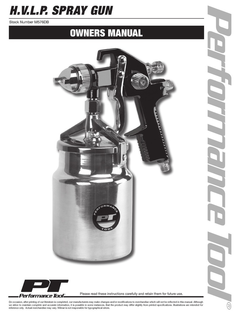
Performance Tool M576DB User manual

Performance Tool

Performance Tool M576DB User manual

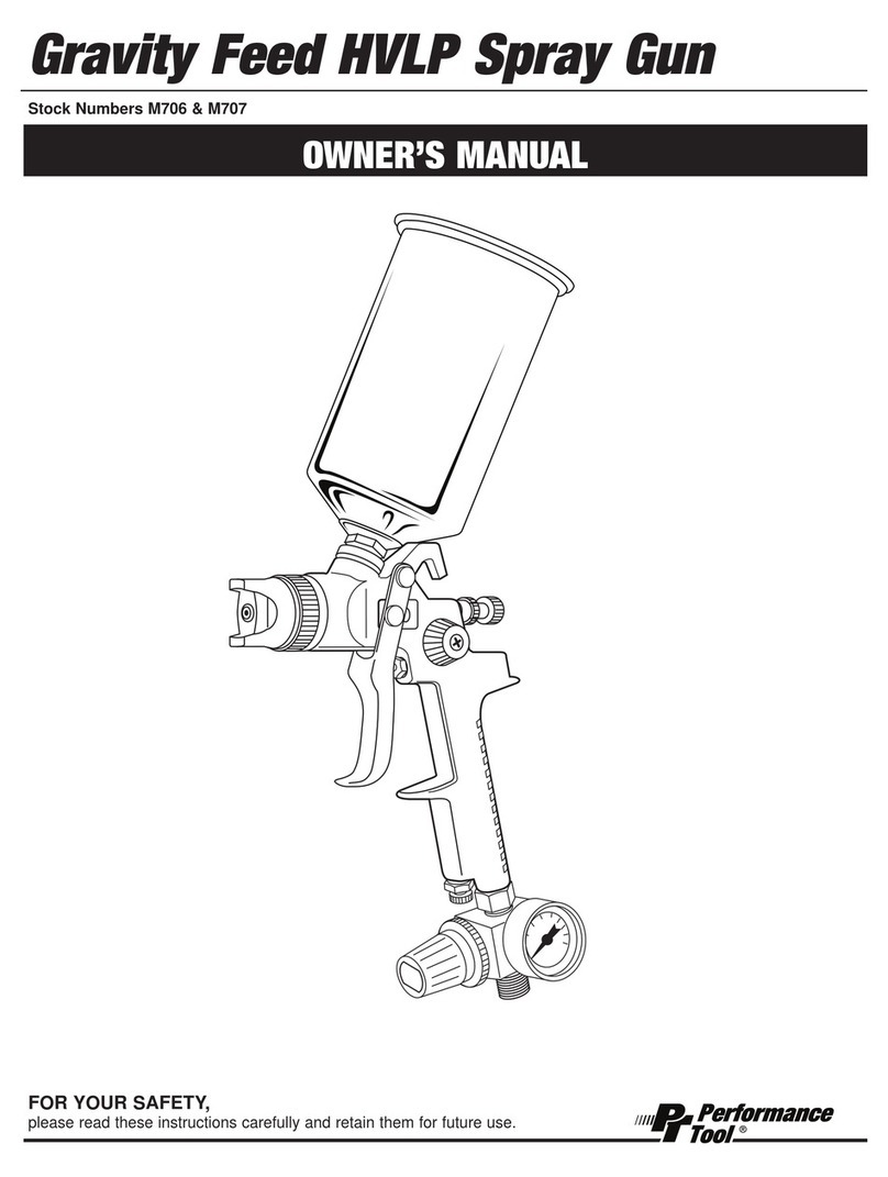
Performance Tool M706 User manual

Performance Tool

Performance Tool M706 User manual

Performance Tool M503 User manual

Performance Tool

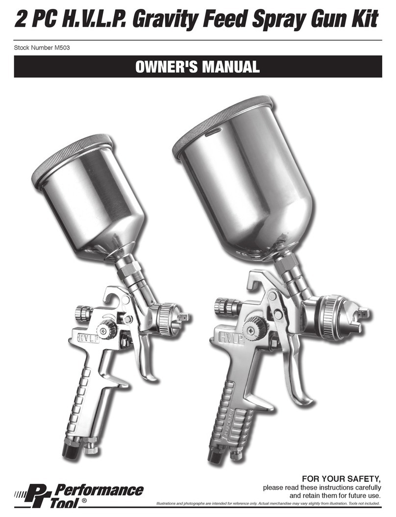
Performance Tool M503 User manual

Performance Tool H.V.L.P. Spray Gun User manual

Performance Tool

Performance Tool H.V.L.P. Spray Gun User manual

Performance Tool M708 User manual

Performance Tool

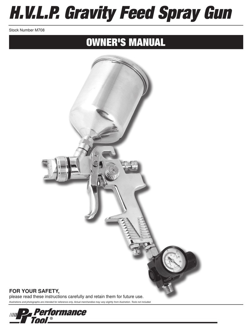
Performance Tool M708 User manual

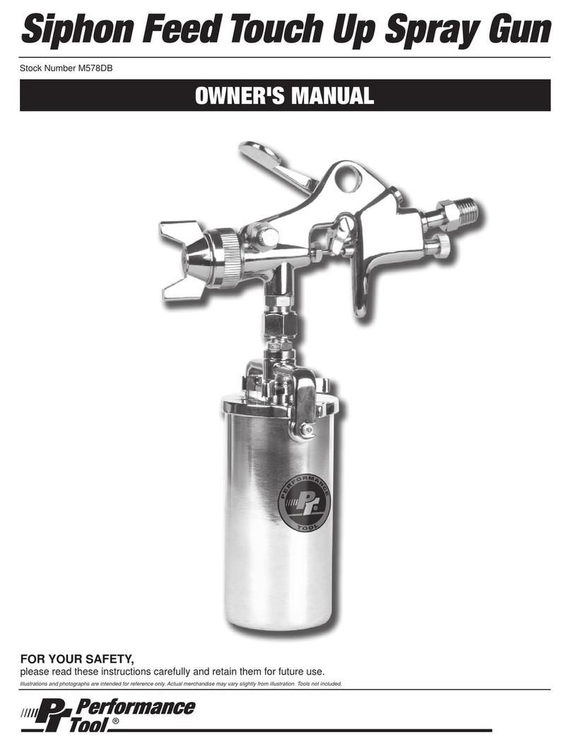
Performance Tool M578DB User manual

Performance Tool

Performance Tool M578DB User manual

Performance Tool M710 User manual

Performance Tool

Performance Tool M710 User manual

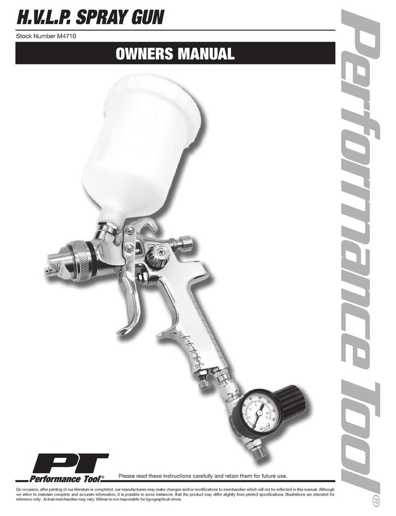
Performance Tool M4710 User manual

Performance Tool

Performance Tool M4710 User manual

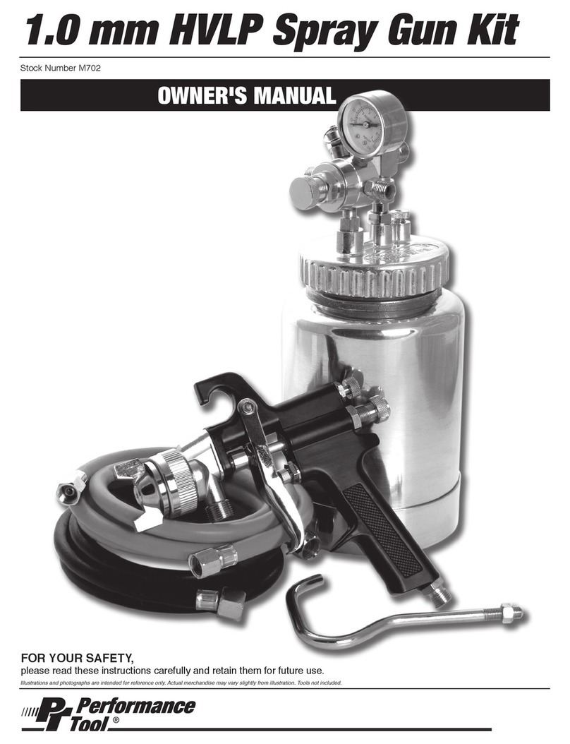
Performance Tool M702 User manual

Performance Tool

Performance Tool M702 User manual

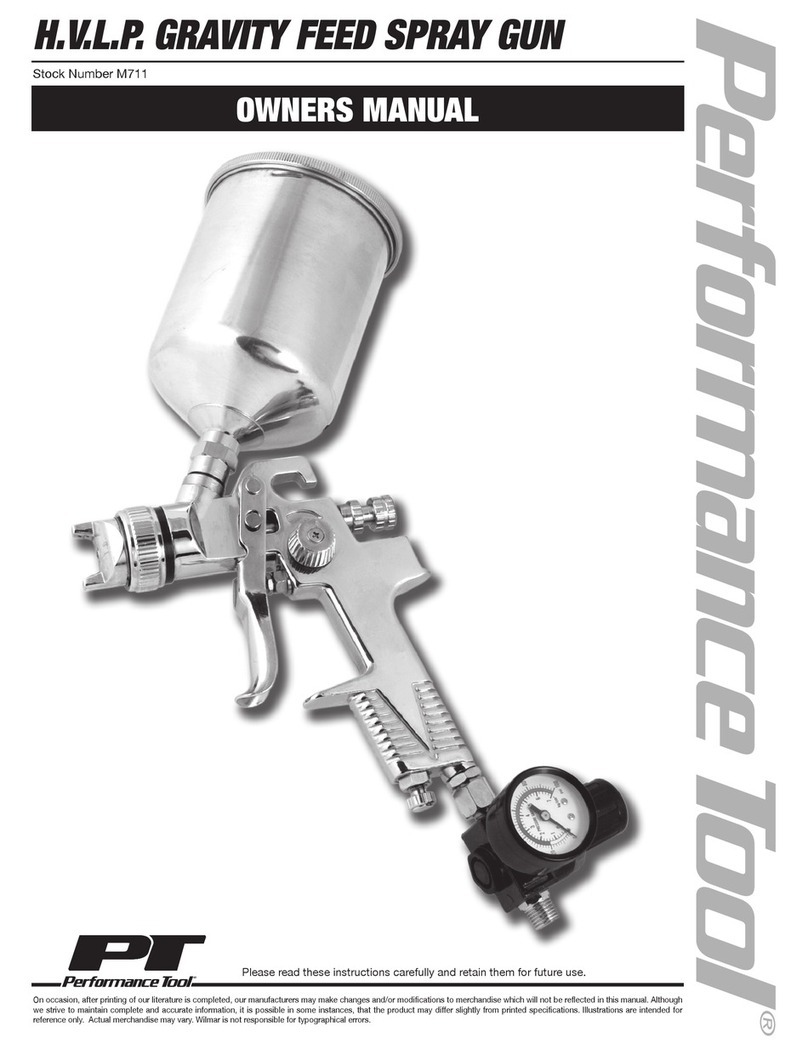
Performance Tool M711 User manual

Performance Tool

Performance Tool M711 User manual

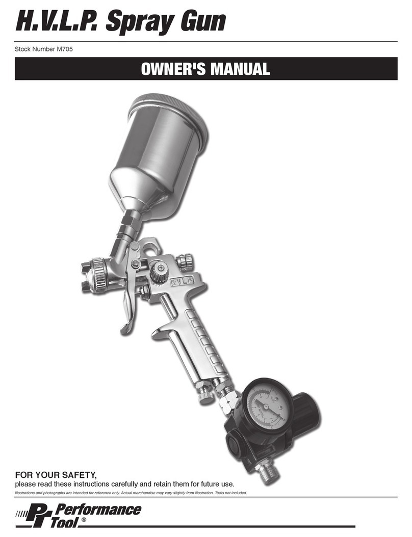
Performance Tool M705 User manual

Performance Tool

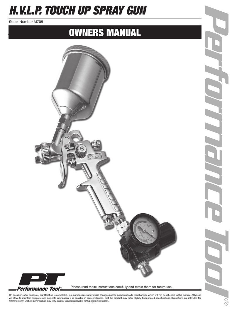
Performance Tool M705 User manual

Popular Paint Sprayer manuals by other brands

Dynalabs DS-MS-20 product manual

Dynalabs

Dynalabs DS-MS-20 product manual

Graco Xtreme 309329 Operation manual

Graco

Graco Xtreme 309329 Operation manual

RED DEVIL 5400-02 owner's manual

RED DEVIL

RED DEVIL 5400-02 owner's manual

DeVilbiss Compact COM-PS430-18-01 Operation manual

DeVilbiss

DeVilbiss Compact COM-PS430-18-01 Operation manual

TeeJet Technologies 844E Installation, programming, and operating manual

TeeJet Technologies

TeeJet Technologies 844E Installation, programming, and operating manual

ST ST104-300L Operation and maintenance instructions

ST

ST ST104-300L Operation and maintenance instructions

Smithco Spray Star 1750 Series Parts & Service

Smithco

Smithco Spray Star 1750 Series Parts & Service

Hardi MASTER PRO VHH Instruction book

Hardi

Hardi MASTER PRO VHH Instruction book

q-Tech QT830 user manual

q-Tech

q-Tech QT830 user manual

Firestone GEOGARD W563581082P Technical Information Sheet

Firestone

Firestone GEOGARD W563581082P Technical Information Sheet

Earth Way S25 SPRAY-PRO Assembly and operating instructions

Earth Way

Earth Way S25 SPRAY-PRO Assembly and operating instructions

Gema OptiFlex Pro B Operating instructions and spare parts list

Gema

Gema OptiFlex Pro B Operating instructions and spare parts list

EUROPRO X-PRO E70 user manual

EUROPRO

EUROPRO X-PRO E70 user manual

Gema OptiGun GA03 Operating instructions and spare parts list

Gema

Gema OptiGun GA03 Operating instructions and spare parts list

Worx Nitro HYDROSHOT WG633E Safety and operating manual original instructions

Worx Nitro

Worx Nitro HYDROSHOT WG633E Safety and operating manual original instructions

Spraying Systems PulsaJet 10000AUH-03-Z1-EPFC user guide

Spraying Systems

Spraying Systems PulsaJet 10000AUH-03-Z1-EPFC user guide

Emist EM360 quick start guide

Emist

Emist EM360 quick start guide

Earth Way SPRAY-PRO S15 Assembly and operating instructions

Earth Way

Earth Way SPRAY-PRO S15 Assembly and operating instructions

manuals.online logo
manuals.online logoBrands
  • About & Mission
  • Contact us
  • Privacy Policy
  • Terms and Conditions

Copyright 2025 Manuals.Online. All Rights Reserved.