Models PTR/PTS Installation & Operation Manual
Printed in USA 3 0213
PRIOR TO INSTALLATION
Uncrating and Inspection
Remove all crating material. Carefully inspect
cabinet for hidden damage. If damage is
discovered, le your claim immediately with the
transport company. Perlick is not responsible for
damage in transit.
Do not cut cardboard
sleeve covering the unit.
Cutting may result in damage to the exterior
of the cabinet. Failure to follow this procedure
may damage the compressor and void
warranty.
1. Uncrate the unit on at, level surface. Remove
the cardboard sleeve by removing the banding
securing the sleeve to the shipping base.
Carefully lift the cardboard sleeve up over the
top of the unit.
2. Carefully lift unit off the base and onto a hand
truck or dolly. Make sure unit is balanced
on transporting device using soft, exible
strapping. Protect unit surfaces with cloth
material where strapping contacts unit.
Do not lift unit by drawer,
shelving or door handles
or damage to the unit could occur.
To prevent personal
injury, two people
minimum required to lift the unit. Larger units
may require additional personnel.
3. Before moving unit, secure door(s) to unit with
tape to prevent from opening.
4. Carefully move unit to installation site and
place in front of opening.
Finished ooring should
be protected with
appropriate material to avoid damage from
moving the unit.
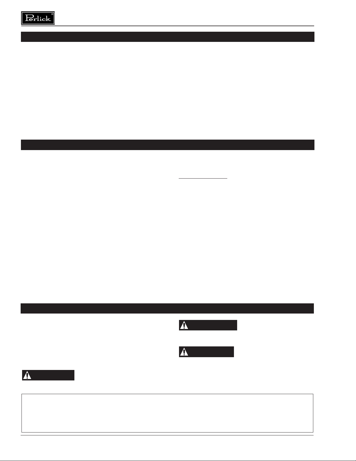
Plumbing
Do not over-tighten drain
fitting or damage to the
threads could occur.
The condensate drain tube (furnished) must be
connected to the unit. One end is attached to the
barbed elbow on the evaporator condensate pan;
the other end is inserted through the evaporator
drain hole and exits the bottom of the cabinet.
The drain hole is located in the cabinet oor pan,
behind the vertical door mullion.
The drain tube must be placed over a oor drain
or into a condensate management system such
as a “Condensate Evapaway’ pan and heater.
Electrical
The cabinet must be connected to a separately
fused power source (see Electrical Specication
Plate afxed to unit) in accordance with National
and Local electrical codes.
Self-contained Perlick units come equipped with
a NEMA 5-15P 90° plug with an 8’ cord extending
beyond the rear of the cabinet. The electrical
outlet must be ush with, or recessed into, the
wall surface.
NOTE: Never use an extension cord to extend the
power cord to the electrical receptacle.
If unit has been laid on its
back or sides, place unit
upright and allow minimum of 24 hours before
connecting power. Failure to follow this
procedure may damage the compressor and
void the warranty.
Do not attempt to operate
the equipment on any
other power source than that listed on the
Electrical Specication Plate attached to the
unit.
ELECTROCUTIONHAZARD!
Electrical grounding is
required. Appliances furnished with a 3-prong
(grounding) polarized plug are equipped for
your protection against possible shock
hazards.
• Never remove the round grounding prong
from the plug.
• Never use a 2-prong adapter.
• Never use extension cord to connect
power to the unit.
• If a 2-prong receptacle is encountered, or
a longer power cord is required, contact
a qualied electrician to have it replaced
in accordance with applicable electrical
codes.
Failure to comply with these
electrical guidelines may
result in possible death or serious injury, re,
or loss of property.