Pertici CM4/S Instruction manual

Via delle Città (SS. 429) 41/43
P.O. BOX 196 - 50052 CERTALDO (FI) ITALY
TEL. +39 0571 651204 - FAX +39 0571 652991
e-mail: pertici@pertici.it - http://www.pertici.it
Ver.: 2.0
MANUALE D’ISTRUZIONE PER L’USO E LA
MANUTENZIONE PULITRICE AUTOMATICA CM4S 1
File: 2240.doc - 03/11/03 14:27

TABLE OF CONTENTS
TABLE OF CONTENTS ...........................................................................................................2
1. INTRODUCTION..................................................................................................................4
2. GENERAL PRECAUTIONS .................................................................................................5
3. CHARACTERISTICS ...........................................................................................................6
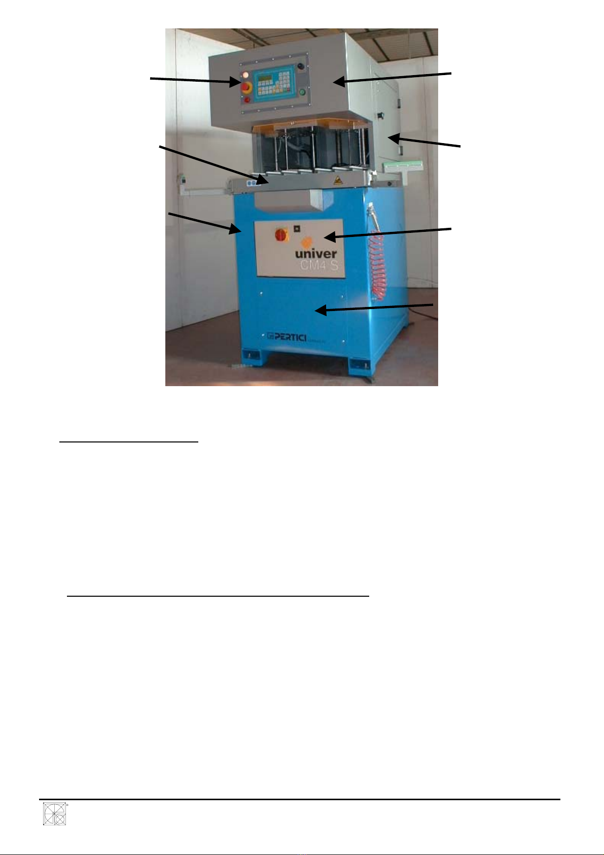
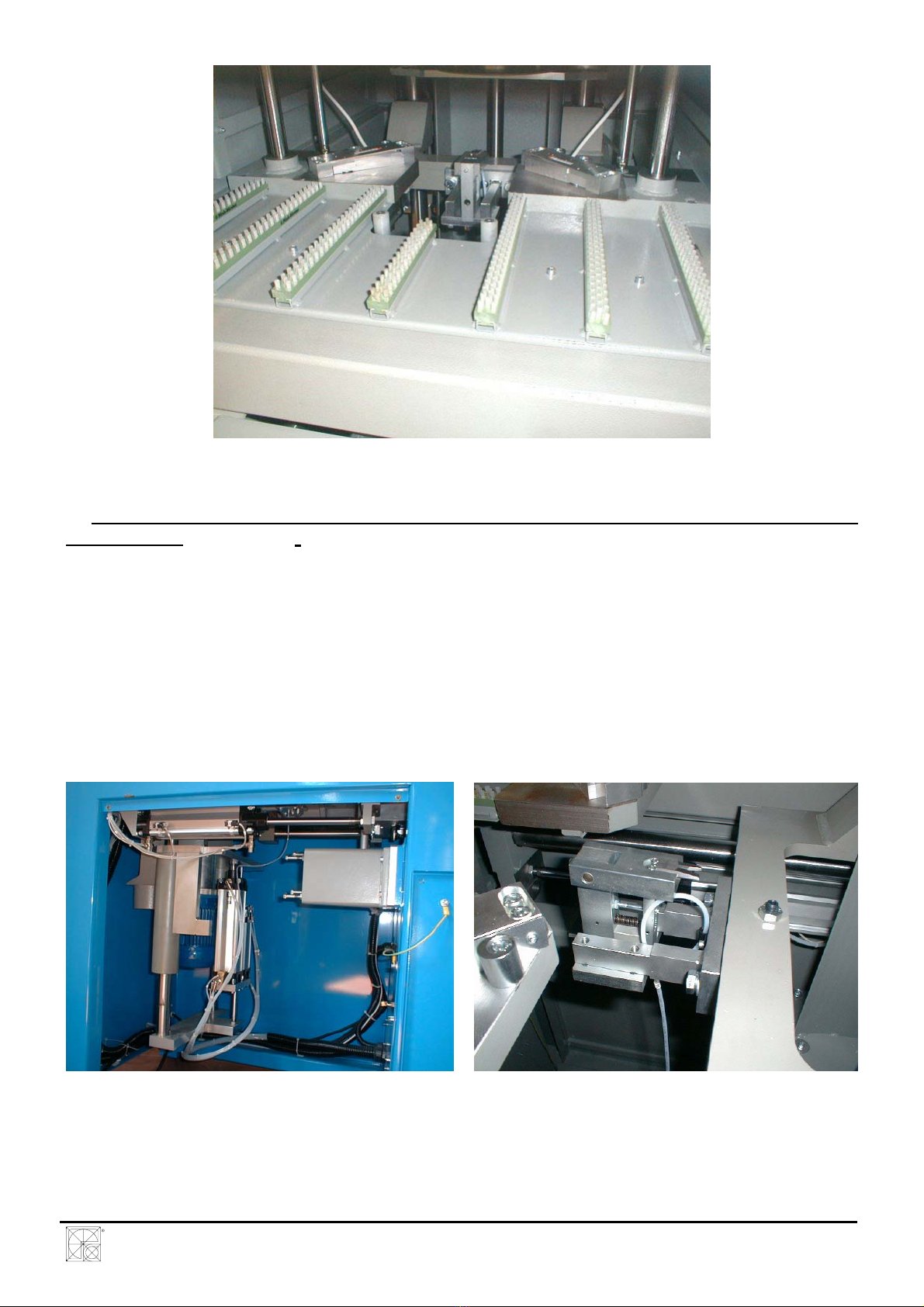
3.1 Description of the machine ......................................................................................6
3.2 Technical features ...................................................................................................10
3.3 Use limits.................................................................................................................10
3.4 Standard kits ...........................................................................................................11
3.5 Optional/Spare parts................................................................................................11
3.6 Tools to be used......................................................................................................11
3.6.1 Groups of milling cutters ............................................................................11
3.6.2 Height of milling cutter groups....................................................................12
3.6.3 Base diameter of the milling cutters ...........................................................12
3.6.4 Quantity of cutting bits ...............................................................................13
3.6.5 Max. diameter of milling cutters .................................................................13
3.6.6 Min. diameter of milling cutters ..................................................................13
3.6.7 Connecting hole of milling cutter pack .......................................................13
3.6.8 Balancing of milling cutter packs................................................................13
3.6.9 Knifes for welding seal removal .................................................................13
3.7 Conformity with safety standards.............................................................................14
4. COMMISSIONING ...............................................................................................................15
4.1 Transport .................................................................................................................15
4.2 Positioning...............................................................................................................15
4.3 Safety zones and dimensions..................................................................................17
4.4 Setting up for work...................................................................................................18
4.5 Compressed air circuit hook-up...............................................................................20
4.6 Connection of the electric equipment ......................................................................21
4.7 Connection to the exhaust system...........................................................................22
5. USE......................................................................................................................................24
5.1 Checks before use...................................................................................................24
5.2 Description of controls .............................................................................................24
5.3 Operating cycle........................................................................................................26
5.4 Emergency device ...................................................................................................27
5.5 Functionality of sensors...........................................................................................27
5.5.1 Microswitches for holding shoulders ..........................................................27
5.5.2 Microswitches for safety of the locking plate..............................................28
5.5.3 Reed sensors.............................................................................................29
5.5.4 Resistive linear transducers .......................................................................29
5.6 Precautions to ensure safety during use .................................................................29
6. ADJUSTMENTS FOR TOOLS OPERATIONS ....................................................................30
6.1 Adjustment of milling cutter packs height ................................................................30
6.1.1 Adjustment of the height of the milling cutter pack 3..................................30
6.1.2 Adjustment of the height of the milling cutter pack 1..................................31
6.1.3 Adjustment of the height of the milling cutter pack 2..................................32
6.1.4 Adjustment of the height of the milling cutter pack 4..................................33
6.2 Adjust of the milling depth .......................................................................................33
6.3 Adjustment and replacement of knifes for welding seal removal .............................34
6.4 Programming of the automatic profile recognition system .......................................36
6.4.1 Modification of the data for the automatic recognition................................37
7. NOISE..................................................................................................................................38
8. MAINTENANCE...................................................................................................................39
MANUALE D’ISTRUZIONE PER L’USO E LA
MANUTENZIONE PULITRICE AUTOMATICA CM4S 2
File: 2240.doc - 03/11/03 14:27

8.1 Ordinary maintenance .............................................................................................39
8.2 Extraordinary maintenance (weekly) .......................................................................39
8.3 – Replacement of milling cutters..............................................................................39
8.3 – Replacement of knifes for welding seal removal...................................................41
9. SPARE PARTS....................................................................................................................42
10. LIST OF ENCLOSURES TO THE INSTRUCTION MANUAL.............................................43
ENCLOSURE 1 ............................................................................................44
ENCLOSURE 2 ............................................................................................45
ENCLOSURE 3 ............................................................................................48
ENCLOSURE 4 ............................................................................................51
ENCLOSURE 5 ............................................................................................53
ENCLOSURE 6 ............................................................................................54
ENCLOSURE 7 ............................................................................................55
ENCLOSURE 8 ............................................................................................56
MANUALE D’ISTRUZIONE PER L’USO E LA
MANUTENZIONE PULITRICE AUTOMATICA CM4S 3
File: 2240.doc - 03/11/03 14:27

1. INTRODUCTION
This manual is intended for the operator and in particular for the personnel responsible for
safety in the use of the machine.
It is therefore recommended to carefully read the contents of this manual, and in particular
those sections on precautions and methods of use, and to keep the manual in its holder in a
safe place near the machine to facilitate future consultation as and when required.
To make the manual easier to follow reference is made to diagrams from the enclosures. The
general reference is DWG. Ax.y whereby:
A indicates that the diagram is from an enclosure,
x indicates the number of the enclosure,
y indicates the page number of the enclosure.
MANUALE D’ISTRUZIONE PER L’USO E LA
MANUTENZIONE PULITRICE AUTOMATICA CM4S 4
File: 2240.doc - 03/11/03 14:27

2. GENERAL PRECAUTIONS
2.1 To use the machine correctly, the user must have a thorough knowledge of these user
instructions and of all the hazards related to an improper use of the machine. Only expert
and authorised personnel must therefore use the machine.
2.2 Safety in the use of the machine can only be guaranteed for the functions and materials
listed in this instruction manual. PERTICI S.p.A. declines all liability if the machine is used
for purposes other than those stated and in ways that do not conform to the user
instructions.
2.3 PERTICI S.p.A. declines all liability for any matters relating to the safety, reliability and
performance of the machine if the instructions and recommendations given in this manual
are not observed, with particular reference to: assembly, use, routine and non-routine
maintenance and repair work.
2.4 The user’s electrical system must comply with 64-8 EEC Standards (CENELEC HD 384,
364 - 4/41 IEC).
The manufacturer accepts no liability if the machine is not correctly connected to the
unipotential ground circuit and if protective devices co-ordinated in such a way as to
guarantee the automatic breaking of the circuit in accordance with the above stated
specifications are not installed upstream of the machine.
2.5 Only original spare parts must be used for non-routine maintenance and repair work.
2.6 For all repair work, contact the technical assistance service designated by the supplier of the
machine. Responsibility for the perfect working order of the machine rests entirely with the
user if it is repaired or maintained incorrectly by non-specialist or unauthorised personnel.
2.7 In particular, maintenance work on the electrical equipment must be performed by specialist
or authorised personnel using original spare parts. The machine must be disconnected from
the electrical power supply before performing any of these operations.
2.8 The automatic corner cleaning machine is designed for the use in covered industrial
environments; any use in other areas relieves PERTICI S.p.A. of all liability.
2.9 The person in charge of the machine must be trained in the correct use of the machine
itself, the safety devices and accessory equipment.
2.10 The safety devices provided with the machine are already correctly installed and attached.
Both the safety devices and the entire machine must be submitted to routine and non-
routine maintenance procedures at the specified intervals.
2.11 Before starting each job and switching on the machine, make sure that there are no chips
or waste material from previous jobs on the work surface.
2.12 The operator must wear suitable clothing and use the correct safety equipment for the type
of work being performed (protective gloves, soundproofed ear guards, safety goggles).
Never wear bracelets or other articles, which may be caught up in the machine.
2.13 Before starting any job with the machine, ensure that there are no persons or other
potential sources of danger in the vicinity of the machine (an area of 150 cm around the
machine) (DWG. A1.9)
MANUALE D’ISTRUZIONE PER L’USO E LA
MANUTENZIONE PULITRICE AUTOMATICA CM4S 5
File: 2240.doc - 03/11/03 14:27

2.14 Make sure the electricity mains connection cable is undamaged and correctly positioned.
2.15 Do not place or use inflammable substances near the machine, as the sparks produced
may cause fires or explosions.
2.16 The operator must exercise the utmost care when, by entering the edge to be polished, the
locking device is activated.
2.17 Always consider the possible consequences before approaching any of the more
dangerous zones (locking zone and milling zone) with your hands.
3. CHARACTERISTICS
The CM4/S produced by PERTICI S.p.A. must be used to remove the rests of PVC that have
been generated during the thermowelding process of the frame and door angles, for the
construction of window and door fixtures.
- Possibility to mount a maximum of 4 groups of milling cutters to remove the welding seals from
the external angle.
- Cutting devices to remove the upper and lower welding seals
- Automatic device for frame positioning
- Automatic device to start the working cycle.
- Working cycle controlled by an electronic unit (PLC)
- Independent adjustment of the milling (polishing) depth on the external side of the angle.
- Low-pressure safety device for frame locking.
- Possibility to modify the working cycle, excluding some machining.
3.1 Description of the machine
A) Base plate (DWG. A1.1)
The base plate consists of a 3-mm thick sheet bed.
The elements of the base plate are bent in order to obtain the maximum rigidity and are
assembled by means of an intermittent weld. The control cabinet is mounted on the base plate
by means of commercial bolts and nuts, while the panel of pneumatic components is connected
to the base plate by welding.
The machine is also supplied complete with four vibration-damping feet, which are fixed to the
lower part of the base plate and permit to place the machine on the floor.
MANUALE D’ISTRUZIONE PER L’USO E LA
MANUTENZIONE PULITRICE AUTOMATICA CM4S 6
File: 2240.doc - 03/11/03 14:27

CONTROL
PANEL TOTAL PROTECTION
OF WORKING AREA
LOAD BEARING
FRAME
LEFT OPENABLE
PANEL
BASE PLATE
DOOR OF ELECTRIC
CABINET
DOOR OF PNEUMATIC
PANEL
Dwg. A1.1
B) Load bearing frame (Dwg. A1.1)
It consists of a structure of steel plates and tubular.
The elements composing the frame are assembled by intermittent weld in order to obtain the
maximum rigidity. The following groups are connected to the holding frame by means of
commercial bolts and nuts:
- holding surface and automatic frame positioning
- group for lifting and forward movement of cutter’s packs
- motor and cutter pack support group
- locking device with upper knife for welding seal removal
- total safety guards for moving parts and working area
C) - Holding surface and automatic frame positioning group (Dwg. A1.2)
It is composed of a sheet structure connected to the holding frame, on which have been fixed
brushes with short and hard bristles, turned upwards, which permit to support the frame to be
processed at the same height of the reference horizontal surfaces for working on the load
bearing frame and on which have been fixed the reference shoulders which permit to obtain the
proper frame position. In order to obtain this position, the operator has to put the frame by hand
onto the machine and push it into contact with the two shoulders. In this way, the mobile part of
the shoulders is able to activate the microswitches placed in the fixed part and to start the
working cycle. Automatically a mechanical device controlled by pneumatic cylinders is activated,
to position the frame in the right position to be processed.
MANUALE D’ISTRUZIONE PER L’USO E LA
MANUTENZIONE PULITRICE AUTOMATICA CM4S 7
File: 2240.doc - 03/11/03 14:27

Dwg. A1.2
D) Group for lifting and forward movement of cutter’s pack and lower cutting device for welding
seal removal (Dwg. A1.3) - (Dwg. A1.4)
It consists of a structure made of iron casting details, steel sheet assembled by means of
intermittent weld, steel plates and rods. This structure works as a support for the motor group,
for the support of the milling cutter’s packs and for the lower cutting device. On this structure are
mounted the pneumatic actuator for lifting of the milling cutter’s packs, the pneumatic actuator
for the forward movement of the cutter’s packs and the actuator for the movement of the lower
cutting device. The pneumatic actuators for lifting, permit the vertical positioning of the 4 cutter
groups, the pneumatic actuator for the forward movement permit the movement of the cutter’s
packs in the frame direction to allow the external milling (polishing) processing. At the same
time, the actuator for the movement of the lower cutting device for welding seal removal controls
the movement upwards, thus permitting to inhibit or to activate the same cutting device.
Dwg. A1.3 Dwg. A1.4
MANUALE D’ISTRUZIONE PER L’USO E LA
MANUTENZIONE PULITRICE AUTOMATICA CM4S 8
File: 2240.doc - 03/11/03 14:27

E) Motor and milling cutter pack holding group (Dwg. A1.3)
It consists of a structure made of steel sheet details, assembled by means of intermittent weld,
aluminium plates and steel rods. A special electric motor with a long shaft has been fixed on this
structure, in order to permit to place up to 4 milling cutter packs. The milling cutter packs are
mounted directly on the motor shaft without any transmission. The motor shaft is supported at
the end to give a bigger rigidity and to eliminate the possible vibrations during the rotation and
processing phases. On the same structure has been mounted a safety guard for the milling
cutter packs made of electro-welded sheet, which can be opened in order to enable the
replacement of the milling cutter packs and that works also as exhaust hood for the chips
produced during processing.
F) Group with locking device and upper cutting device for welding seal removal (Dwg. A1.5) -
(Dwg. A1.6)
It consists of a structure made of aluminium sheet details with steel plates and rods. This
structure is used to carry out the frame locking, first at a low pressure for the operator’s safety
and then at a high pressure for the machining. It works also as a support for the upper cutting
device for welding seal removal and for the automatic profile recognition (optional). On this
structure are assembled: the pneumatic actuators for the vertical blocking, the pneumatic
actuator for the forward movement of the upper cutting device and, if the above mentioned
optional is present, all relevant limit switch sensors and linear potentiometers, which permit to
read the form and the dimensions of the profile composing the frame to be processed.
Dwg. A1.5 Dwg. A1.6
G) Total safety guards for moving parts and working area (Dwg. A1.1)
It consists of a structure made of steel sheet, assembled by means of intermittent weld, which
protects the working area and all other dangerous zones of the machine. On this safety guard
have been placed the electronic control unit of the machine as well as some control push
buttons and some signalling lamps. Limit switch controlled Inspection doors have been made to
carry out the replacement of the cutter’s packs, of the knifes for welding seal removal and to
accede to the internal components in case of maintenance works.
MANUALE D’ISTRUZIONE PER L’USO E LA
MANUTENZIONE PULITRICE AUTOMATICA CM4S 9
File: 2240.doc - 03/11/03 14:27

3.2 Technical features
IMPORTANT !!!!: USE ONLY MILLING CUTTERS WITH THE CHARACTERISTICS
SPECIFIED IN THIS MANUAL.
3.3 Use limits
The corner cleaning machines type UNIVER CM4/S, produced by PERTICI S.p.A. are used for
the processing of plastic profiles, mainly of PVC (Polyvinyl chloride).
The machines have been designed and built to be used in covered industrial environments.
Conditions of use:
Ambient temperature range: from 10°C to 40°C.
Humidity up to 90% at a temperature of 20°C
The maximum diameter of the cutter to be mount on these models in order to work in safety
conditions is:
Ø = 250 mm
The maximum dimensions of the profile composing the frame that can be processed in safety
conditions are:
Max. profile height = 200 mm
Max. profile width = 140 mm
WARNING !!!!! ANY USE OF THE MACHINE FOR PURPOSES OTHER THAN THOSE
INTENDED AND STATED BY THE MANUFACTURER IN THIS USER INSTRUCTION
MANUAL AND IN THE PROMOTIONAL BROCHURE WILL BE CONSIDERED AS
IMPROPER.
PERTICI S.p.A. DECLINES THEREFORE ANY LIABILITY IF THE OPERATOR HAS NOT
OBSERVED THE MANUFACTURER’S SPECIFICATIONS.
MANUALE D’ISTRUZIONE PER L’USO E LA
MANUTENZIONE PULITRICE AUTOMATICA CM4S 10
File: 2240.doc - 03/11/03 14:27

3.4 Standard kits
UNIVER CM4/S
Couple of knifes for upper and lower welding seal
removal on not coated profiles
Safety guard of milling cutter groups with
arrangement for exhaust coupling
3.5 Optional/Spare parts
UNIVER CM4/S
Adjustable supporting arms for profiles
Device for the automatic profile recognition (with limit switches and linear
potentiometers)
Couple of knife for welding seal removal on coated profiles
Industrial dust exhaust three-phase unit (standard) – 2 bags – KW. 1,5 with
accessories
Device for the automatic turning on of exhaust unit
Set of milling cutters (by sample)
3.6 Tools to be used
To execute the corner cleaning the CM4/S uses two types of tools.
- Packs of milling cutters
- Knifes for welding seal removal
3.6.1 Groups of milling cutters
This tool is used to remove the welding seal from the frame external angle.
The milling cutter pack is realised joining various milling cutters with different diameters and
thickness with the aim to “copy” the profile shape.
MANUALE D’ISTRUZIONE PER L’USO E LA
MANUTENZIONE PULITRICE AUTOMATICA CM4S 11
File: 2240.doc - 03/11/03 14:27

3.6.2 Height of milling cutter groups
The machine allows seating 4 groups of milling cutters.
Each pack must have a height of 97 mm.
If the milling cutters composing the group reach a lower height, some spacers with the proper
height must be added.
3.6.3 Base diameter of the milling cutters
To make up the groups it is necessary to determine the diameters of the single milling cutters
composing each group.
All milling cutter diameters have a direct ratio with a reference diameter (base diameter).
The base diameter for the CM4/S is of 80 mm and refers to the milling cutter, which has to
polish the profile part in contact with the holding shoulders.
Starting from the base diameter of the milling cutters, act as follows to calculate the diameter of
the other milling cutters.
Examining a straight profile piece, measure the distance from the surface resting on the
shoulders and the other surfaces to be polished.
Multiply each measure by 2 (to calculate the diameter and not the ray). The result must be
multiplied by 1.414 (to calculate the effective dimension at 45°) and finally added to the base
diameter (80-mm).
Ex. The milling cutter immediately above the base one must have a diameter of:
MANUALE D’ISTRUZIONE PER L’USO E LA
MANUTENZIONE PULITRICE AUTOMATICA CM4S 12
File: 2240.doc - 03/11/03 14:27

80 + (19.3 x 2 x 1.414) =134.58 so approximately 134.6 mm
3.6.4 Quantity of cutting bits
To obtain a good quality of the machining, the PERTICI SPA company suggests the use of
milling cutters with at least 8 (eight teeth) cutting bits.
3.6.5 Max. diameter of milling cutters
The CM4/S permits to install milling cutters with a max. diameter of 260 mm
3.6.6 Min. diameter of milling cutters
The CM4/S permits to install milling cutters with a min. diameter of 70 mm.
3.6.7 Connecting hole of milling cutter pack
The diameter of the milling cutter holding shaft of the CM4/S is Ø 32 h6 (tolerance 0 / -0.016).
The optimum coupling happens when the connecting hole of the milling cutter has a diameter of
Ø 32 G7 (tolerance +0.009 /+0.034).
3.6.8 Balancing of milling cutter packs
Before using a milling cutter pack, it is very important to check its balancing.
The milling cutter pack at the rotating speed of 3000 rounds per minute must not operate a
transversal force greater than 1 gram-force.
ATTENTION: THE USE OF NOT BALANCED MILLING CUTTER PACKS INVOLVES
DAMAGES TO THE BEARINGS OF THE MOTOR SUPPORTING THE MILLING CUTTER
HOLDING SHAFT.
3.6.9 Knifes for welding seal removal
The CM4/S is equipped with two knifes to remove the upper and lower welding seal.
The machine permits the machining of almost all types of commercial profiles.
The standard kit of the machine consists in knifes producing a 3-mm width and 0.5 mm depth
trace.
MANUALE D’ISTRUZIONE PER L’USO E LA
MANUTENZIONE PULITRICE AUTOMATICA CM4S 13
File: 2240.doc - 03/11/03 14:27

As optional can be supplied knifes with a “ZERO PROFILE”, which do not cut the profile very
deep. These knifes are suitable for coloured and/or coated profiles.
3.7 Conformity with safety standards
The corner cleaner machines type UNIVER CM4/S have been designed and built in compliance
with the following directives:
EEC STANDARD 89/392 and following modifications (Machine directive).
EEC STANDARD 89/336 and following modifications (Electromagnetic Compatibility).
The following standards and technical specifications have been used:
D.P.R. N°547 (27.4.1955)
EN 60240-1 standards (September 1993) IEC 44-5/IInd edition.
EN 292-1 (1991)and UNI EN 292, part 1, standards.
EN 292-2 (1991) UNI EN 292, part 2, standards.
EN 50081 - 1 (1992) standards.
EN 50082 - 1 (1992) standards.
MANUALE D’ISTRUZIONE PER L’USO E LA
MANUTENZIONE PULITRICE AUTOMATICA CM4S 14
File: 2240.doc - 03/11/03 14:27

4. COMMISSIONING
4.1 Transport
The corner cleaner machines type UNIVER are shipped fully greased and wrapped in heat-
shrink nylon.
The sturdy design and form of the machines guarantee their safe and damage-free shipment
and storage.
A forklift truck can lift the machines by inserting the forks at the points marked on the machine
packaging. (DWG. A1.7)
DWG. A1.7
If the machine is packed in a wooden crate, the fork insertion points are marked on the crate
itself.
Take great care when performing these operations in order to avoid injury to persons and
damage to the machine or property.
4.2 Positioning
The machine must be positioned on a stable floor. Do not install the machine near to areas
containing gas or flammable substances, as the sparks and glowing fragments produced and
scattered may cause explosions or fires.
Position the machine in a place that is easily accessible for the various works and various hook-
ups to:
1) The electric equipment
2) The compressed air circuit
MANUALE D’ISTRUZIONE PER L’USO E LA
MANUTENZIONE PULITRICE AUTOMATICA CM4S 15
File: 2240.doc - 03/11/03 14:27

3) The chip exhaust equipment
Make sure the lighting is adequate for the whole machine
Remove the machine from its packaging and make sure it has incurred no damage during
shipment.
Remove the packaging: a forklift truck can now lift the machine. If transferred by forklift truck,
the forks must be inserted in the lower part of the base plate. (DWG. A1.8)
DWG. A1.8
Before placing the machine definitely on the floor, it is necessary to mount the four vibration-
damping feet supplied together with the machine.
Avoid knocks, jolts and sudden movements when handling the machine.
PERTICI SPA declines all liability for damages caused during shipment. It is therefore
important to check the state of the packaging at the time of purchase.
MANUALE D’ISTRUZIONE PER L’USO E LA
MANUTENZIONE PULITRICE AUTOMATICA CM4S 16
File: 2240.doc - 03/11/03 14:27

4.3 Safety zones and dimensions
Once the machine has been moved to the place of its definitive installation and the packaging
has been removed, proceed with the installation. Take care to leave around the machine the
necessary space for the personnel for normal operations and for inspection and maintenance
works.
The space required to work correctly is of 150 cm all around the machine.
In the following picture are indicated the safety areas around the machine where the utmost
care must be taken to people or objects, which may constitute obstacles or hazards during
work. (DWG. A1.9)
DWG. A1.9
MANUALE D’ISTRUZIONE PER L’USO E LA
MANUTENZIONE PULITRICE AUTOMATICA CM4S 17
File: 2240.doc - 03/11/03 14:27

4.4 Setting up for work
Levelling.Position a spirit level on the frame support surface and verify that the machine is
levelled both lengthwise and crosswise. To level the machine act as follows:
- screw or unscrew the four vibration-damping feet 1 (Dwg. A1.10) by inserting the 12 mm key,
supplied with the machine, into point (A).
- Tighten the four nuts 2 (Dwg. A1.10) using the 19 mm key supplied with the machine.
DWG. A1.10
The support surface of this machine model is wide enough to ensure a good stability and to
avoid the machine tilting. The machine does not need, therefore, a permanent anchoring to the
floor.
After placing and levelling, remove the blocking elements (wooden details) of the moving parts
of the machine that have been placed to carry out the transport and moving operations in safety
conditions. (DWG. A1.11) - (DWG. A1.12)
REMOVE
REMOVE
DWG. A1.11
MANUALE D’ISTRUZIONE PER L’USO E LA
MANUTENZIONE PULITRICE AUTOMATICA CM4S 18
File: 2240.doc - 03/11/03 14:27

REMOVE
DWG. A1.12
At this moment, the operations to be done concern the connection of the various systems as
described in chapters 4.5 and 4.6.
Before setting the machine to work, especially if it is the first start-up or when it is installed in a
new working place, it is necessary to consider the following technical information and the
indications concerning the various connection types.
Mounting of profile holding arms (optional).The mounting and adjustment of this device
(optional) is carried out in our workshop during the machine mounting phase, but it is partly
removed by the machine to facilitate the packaging and shipment operations. To mount this
device during the installation phase, proceed as follows:
- Put arm (1) and (2) (DWG. A1.14) into supports (3) (DWG. A1.13) fixed on the base plate of
the machine.
- Mount the bush (6) (DWG. A1.14) and the self-locking nut (7) (DWG. A1.14), using the 24 mm
key supplied. Do not lock the nut completely, but screw it enough to remove the clearance
between the arm and the support, in order to allow the rotation of the same arm.
- The height adjustment of the arm is carried out during the machine mounting phase. Anyway,
it is always better to proceed with a check in the following way:
- carry out a working cycle to block a frame on the working surface;
- check that the parts made of plastic material of the profile supporting arms (4) (DWG. A1.14),
are on the same level of the lower face of the profiles;
- in case the parts made of plastic material result higher or lower, proceed with the height
regulation by loosing screws (5) (DWG. A1.13) only in part, with the 13 mm key supplied. These
screws fix the supports on the base and move the supports upwards and downwards (3) (DWG.
A1.13);
- find the correct position and tighten the screws completely (5) (DWG. A1.13). Carry out this
operation on both sides.
MANUALE D’ISTRUZIONE PER L’USO E LA
MANUTENZIONE PULITRICE AUTOMATICA CM4S 19
File: 2240.doc - 03/11/03 14:27

5
3
DWG.A1.13
7
4
6
1
2
DWG.A1.14
4.5 Compressed air circuit hook-up
Connection to the line can be made by means of a rubber or Rilsan (Din 74324) hose with a
suitable fitting. We recommend to use a supply hose with an internal diameter of not less than
10 mm.
The working pressure of the user’s net must be, with full load not less than 8 bar/atm.
Hook up the line to the slide valve mounted on the FRL air treatment unit and check by moving
the black collar, that the pressure on the gauge reads 8 bar/atm.
If necessary, turn the knob on the FRL air treatment unit (DWG. A1.19) to bring the pressure to
the indicated level.
MANUALE D’ISTRUZIONE PER L’USO E LA
MANUTENZIONE PULITRICE AUTOMATICA CM4S 20
File: 2240.doc - 03/11/03 14:27
Table of contents