Removing the distributor
1. Disconnect the coil power wire.
2. Remove the spark plug wires from the distributor cap.
3. Remove the coil by unsnapping the retainer bail.
4. Unsnap and remove the distributor cap.
5. Note the position of the rotor so that the distributor can be reinstalled in the
same position. Remove the rotor.
6. Remove the two bolts that hold the distributor to the block.
7. Remove the distributor.
Removing the breaker plate
1. Remove the breaker plate retaining ring.
2. Remove the breaker plate hold down screw.
3. Remove the breaker plate.
4. Remove the shim washer from the distributor shaft.
5. Remove the distributor shaft and advance mechanism.
6. Check the distributor for cracks and excess wear.
Modifying the distributor
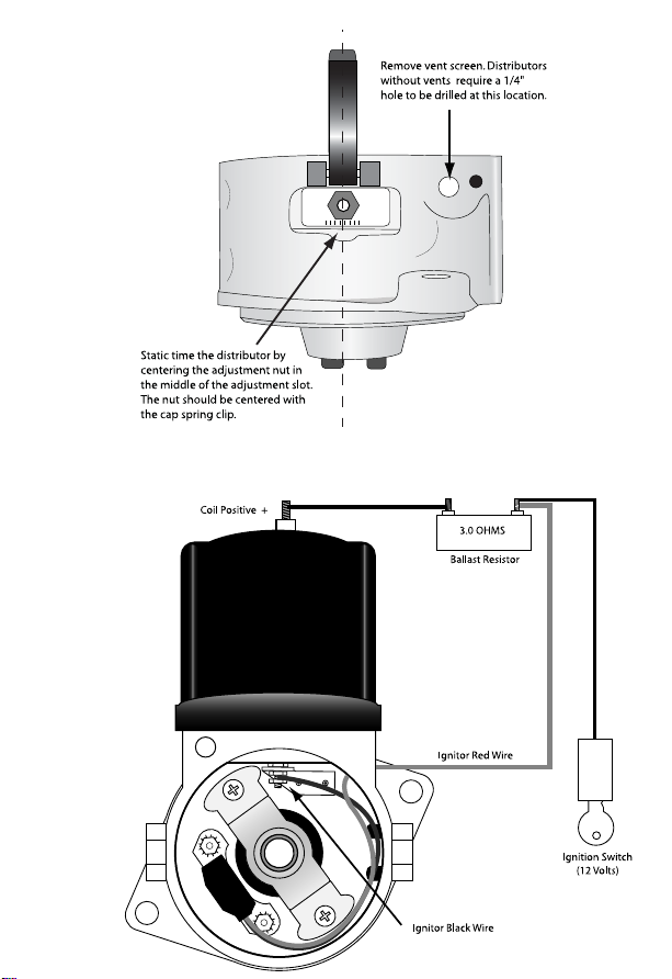
1. To allow the Ignitor wires to exit the distributor, the vent screen closest to the
coil retaining bail must be removed. If the distributor does not have a vent,
drill a 1/4” hole into the distributor housing at the location shown in
Illustration B.
2. This is a good time to clean the distributor thoroughly. Make sure that no
metal debris is left in the distributor.
3. Install the advance mechanism and shaft back into the distributor.
BEFOREYOU START
Read the complete instruction manual before starting installation.
This system is for 12 volt negative ground systems only.
This kit is designed to fit N-Series Ford tractors with front mount distributors.
Some modification to the original distributor is necessary.
A ballast resistor may be required.
Installation Instructions
Part # 1247
LIMITED WARRANTY
PerTronix, Inc. warrants to the original Purchaser of its solid-state
ignition system (product) that the Ignitor shall be free from defects in material
and workmanship for a period of (30) months from the date of purchase.
If within the period of the foregoing warranty PerTronix finds, after inspec-
tion, that the product or any component thereof is defective, PerTronix will, at
its option, repair such products or component or replace them with identical
or similar parts PROVIDED that within such period Purchaser:
1. Promptly notifies PerTronix, in writing, of such defects.
2. Delivers the defective products product or component to PerTronix
(Attn: Warranty) with proof of purchase date; and
3. Has installed and used the product in a normal and proper
manner, consistent with PerTronix printed instructions
THE FOREGOING LIMITED WARRANTY IS EXCLUSIVE AND IN LIEU
OF ALL OTHER WARRANTIES, WHETHER EXPRESS OR IMPLIED,
INCLUDING ANY IMPLIED WARRANTY OR MERCHANTABILITY OR
FITNESS FOR A PARTICULAR PURPOSE.
THE FURNISHING OF A REPAIR OR REPLACEMENT COMPONENTS
SHALL CONSTITUTE THE SOLE REMEDY OF PURCHASER AND THE
SOLE LIABILITY OF PerTronix WHETHER ON WARRANTY, CONTRACT OR
FOR NEGLIGENCE, AND IN NO EVENT WILL PerTronix BE LIABLE FOR
MONEY DAMAGES WHETHER DIRECT OR CONSEQUENTIAL.
440 East Arrow Highway
San Dimas, California 91773
(909) 599-5955 0000-008760
08/04