Pet Stop Indoor Battery Powered Transmitter User manual

Indoor Battery Powered Transmitter
Operators Manual
13010040 Rev - Version B - Addendum

2 | P a g e
Description / Specifications
The Pet Stop Battery Powered Transmitter operates from 4
standard AA alkaline batteries, and produces a signal range of
up to 4’.
The transmitter incorporates an audible low battery warning
which permits mounting the transmitter out of site, such as in
a closet or beneath a couch or bed.
The transmitter is primarily intended for avoidance
applications. To enhance battery life, the transmitter
periodically produces a burst of signal. The rate of
transmission is adjustable as follows: once every 4 seconds
(maximum battery life), once every 2 seconds, once per
second and twice per second (1/2 second interval - minimum
battery life –intended for training only).
Battery life is greatly hinged on range –the greater the range,
the shorter the battery life. Slight downward adjustment of
the range control can greatly extend battery life (see battery
life examples).

3 | P a g e
Specifications:
Maximum range: 3 ¾’ +/-¼’ Up to 5’ of range
can be obtained by increasing
receiver sensitivity from its default
setting.
Range degradation : Range may degrade 6” over life of
batteries
Frequency: Fixed, 7KHZ
Modulation: Fixed, PETSTOP
Battery Life: Maximum of 6 months based upon
a 3’ field. Transmission duration ¼
second, repetition rate 4 seconds.
AA Alkaline battery capacity
assumed to be 3000mA-Hr
Batteries: 4 AA Alkaline –rechargeable
batteries not recommended
Battery Preference: In order based on actual use:
Duracell Ultra/Quantum, Kirkland
(Costco), Rite Aid, E2 Energizer,
RayOVac Max, Energizer Max,
Duracell Copper Top, CVS and
Kodak –note that this is subject to
change, valid at time of printing
Lithium AA batteries will not
significantly increase battery life.
Low Battery : ¼ second beep every 1 to 3
minutes

4 | P a g e
Getting Started: Battery Insertion
Remove the 2 screws from the bottom of the case using a Phillips
screwdriver.
Insert 4 AA batteries in orientation as shown. Batteries are all
oriented in the same direction, the positive end of the battery faces
upwards towards the switches.

5 | P a g e
Upon insertion of last battery, transmitter will power up. It will
produce a 1 second beep while turning on the red transmission LED.
If the transmitter produces a series of rapid beeps for 10 seconds
after power-up, this is an indication that the batteries are low and
should be replaced.
(In normal operation the transmitter will not beep. When the
batteries are low and need to be changed the Transmitter will
produce a very short beep every few minutes.)
Replace the lid, being careful to align the indexing pins with the
base. Re-install the 2 screws you removed earlier being careful not
to over tighten them. They do not need to be tight.
The only visual indication of operation will be a momentary
illumination of the Transmission LED each time the transmitter
produces a burst of signal.
There is no ON/OFF switch. If you do not desire to have the unit
transmitting, simply remove at least 1 battery.
It is recommended to remove all batteries if not being used and
being stored for extended periods.

6 | P a g e
Transmitter Controls / Indicators
Transmission LED:
This LED will illuminate at the end of a transmission packet. This will
let you know the transmitter is functional and assist in ascertaining
range –receiver should activate when light illuminates.
Range Control:
Sets range of transmission. Rotate Clockwise for maximum,
Counter-Clockwise for minimum. Battery life will be maximized by
setting the control to as short of range as practical for the
application.
Duration and Repetition Switches:
These four switches set the transmission duration and the repetition
rate.

7 | P a g e
Setting the Switches:
Switches are set by sliding them up or down. To turn a switch “ON”
slide it to the up position. To turn a switch “OFF” slide it to the
downward position.
Switches 1 and 4 control the repetition rate. This controls how
often the transmitter bursts signal. Transmitter repetition rate can
be set at ½, 1, 2 and 4 second intervals. The slower the repetition
rate (i.e. 4 seconds) the greater the transmitter battery life.
Settings:
1 ON, 4 ON ½ second **
1 OFF, 4 ON 1 second
1 ON, 4 OFF 2 seconds
1 OFF, 4 OFF 4 seconds
** Will result in poor battery life. Only use for initial training.
Transition to a slower repetition rate when proper behavior has
been obtained.

8 | P a g e
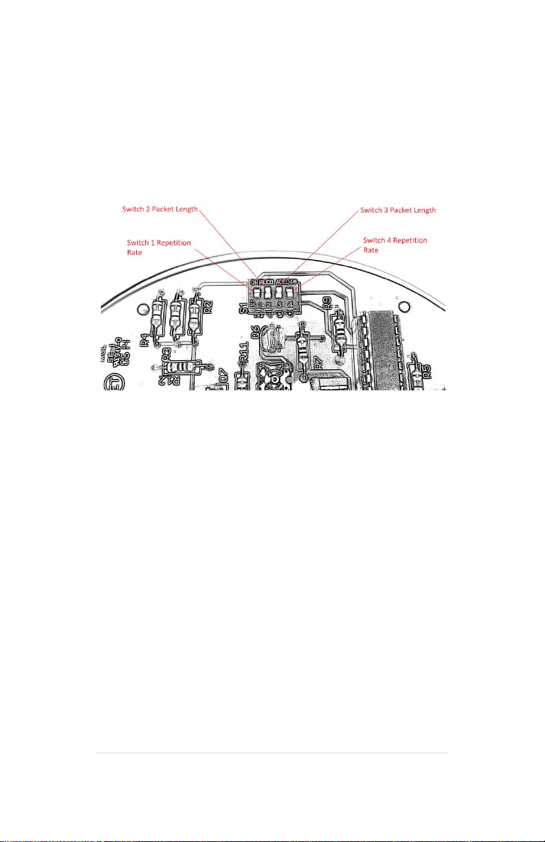
Switches 2 and 3 set the packet length. This controls the length of
the transmitter signal burst. Burst lengths of ¼, ½, ¾ and 1 second
can be selected. A shorter burst length (i.e. ¼ second) will yield a
longer transmitter battery life.
Settings:
2 ON, 3 ON ¼ second –use with Receiver set to “51”, “21”
2 OFF, 3 ON ½ second –use with Receiver set to “52”, “21”
2 ON, 3 OFF ¾ second –use with “51” and “22” ***
2 OFF, 3 OFF 1 second –use with “52” and “22” ***
*** Will result in very poor transmitter battery life! Only use if a
correction is required AND a delay must be used between tone and
correction. Otherwise a shorter duration setting can be used and
only a tone will be emitted by receiver. If a correction is also
required, it is highly recommended to disable the receiver’s delay
(set receiver to “21”).
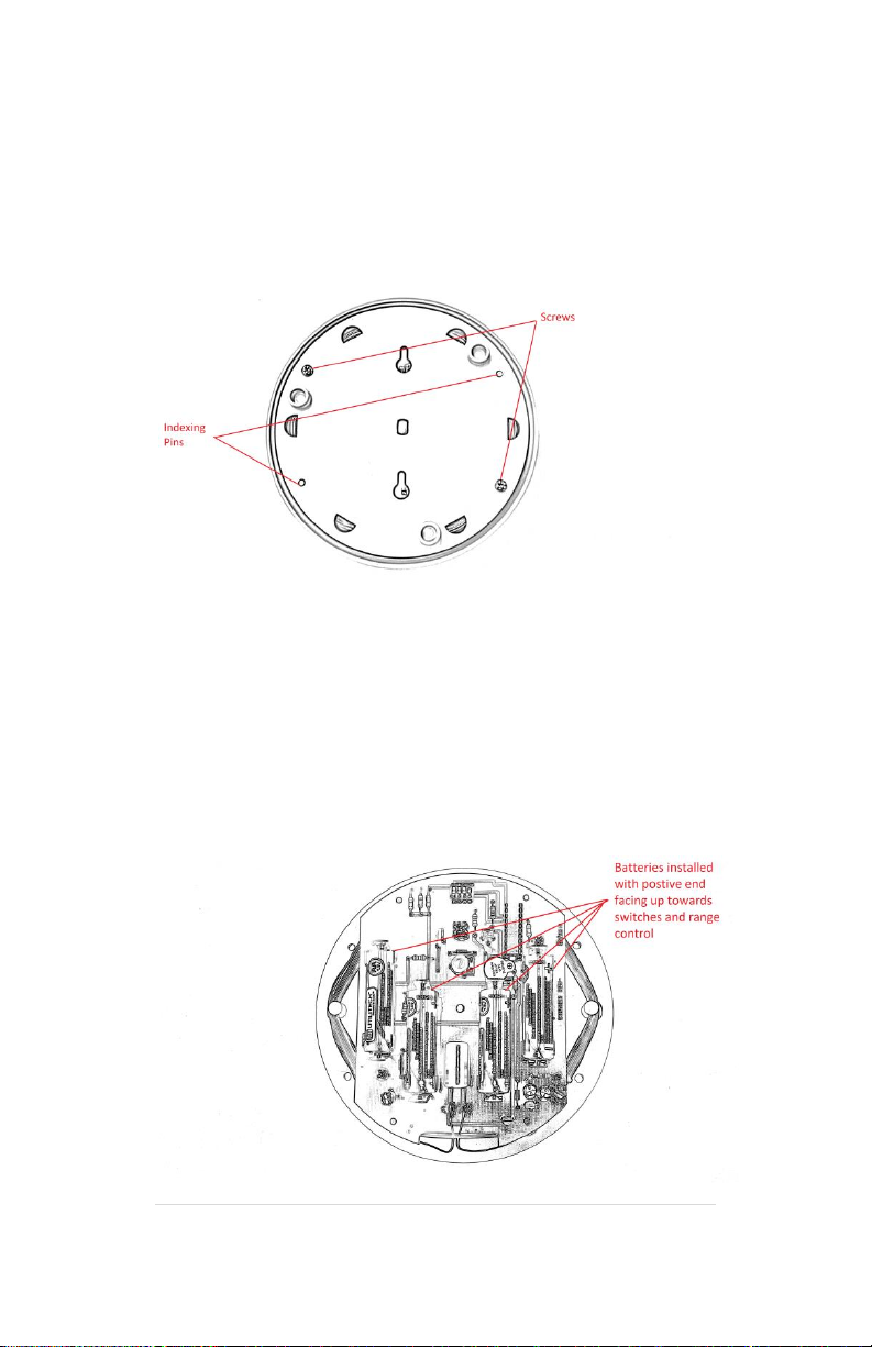
Battery Life:
To maximize transmitters battery life, program receiver for setting
“51” to disable duty cycling, and place transmitter switches 2 and 3
in the on position and switches 1 and 4 in the off position. This will
minimize the amount of time the transmitter needs to produce
signal. Adjust range control for a minimally acceptable signal. If a
physical correction is required set the receiver to no delay (“21”).

9 | P a g e
Battery Life Examples –these are approximations of typical battery
performance –your results may vary:
Switches 2 and 3 set to “ON”, Switches 1 and 4 set to “OFF”
(1/4 second transmission every 4 seconds)
Range Battery Life
Maximum 4 months
3’ 6 months
2’ 12 months
Minimum 38 months
Switch 2 set to “OFF”, Switch 3 set to “ON”, Switches 1 and 4 set
to “OFF”
(1/2 second transmission every 4 seconds)
Range Battery Life
Maximum 2 months
3’ 3 months
2’ 6 months
Minimum 18 months

10 | P a g e
Switches 2, 3 set to “ON”, Switch 1 “OFF”, Switch 4 “ON”
(1/4 second transmission every 1 second)
Range Battery Life
Maximum 1 month
3’ 2 months
2’ 5 months
Minimum 13 months
Switch 2 set to “OFF”, Switch 3 set to “ON”, Switch 1 “OFF”, Switch
4 “ON”
(1/2 second transmission every 1 second)
Range Battery Life
Maximum 2 weeks
3’ 1 month
2’ 3 months
Minimum 6 months

11 | P a g e
Switch 2 set to “ON”, Switch 3 set to “OFF”, Switches 1 and 4 set to
“OFF”
(3/4 second transmission every 4 seconds)
Range Battery Life
Maximum 1 month
3’ 2 months
2’ 4 months
Minimum 9 months
Switch 2 set to “ON”, Switch 3 set to “OFF”, Switch 1 “OFF”, Switch
4 “ON”
(3/4 second transmission every 1 second)
Range Battery Life
Maximum 1 week
3’ 3 weeks
2’ 7 weeks
Minimum 4 months

12 | P a g e
Notes:

13 | P a g e
Addendum: Version B
Additional Features:
ON/OFF Switch (DIP Switch position 6)
Buzzer silence switch (DIP Switch position 5)
Ability to drive an external loop
Dip Position 5:
Place switch in the “ON” position (up) to enable low
battery alert.
Place switch in the “OFF” position (down) to disable the
low battery alert –PLEASE NOTE: in this position
transmitter will NOT alert you to the internal batteries
being weak and needing replaced.
Dip Position 6:
Place switch in “ON” position to turn the transmitter on.
This switch may be moved to the “OFF” position (down)
to disable the transmitter.
External Loop:
Use part # 10210004 (cord set) to make connection to
the transmitter.

14 | P a g e
Maximum loop length is 100’
Wire Gauge requirements:
75’ to 100’: 10 Gauge insulated wire
25’ to 74’: 12 Gauge insulated wire
5’ to 24’: 14 Gauge insulated wire
Hints:
Turn range control as low as possible to maximize
battery life while testing to make sure animal cannot
enter area. As an example, a 5’ x 40’ flower bed can
have the range control lowered far enough to allow
operation from batteries for 1 year (1/4 second
duration every 4 seconds).
Unit can be buried underground utilizing a waterproof
box. NEMA rain-tight enclosures are an excellent choice
but expensive. Round “Tupperware” container can also
be used - simply cut small hole for external loop wires
to exit and seal with a silicone sealant.
Other Pet Stop Pet Care Product manuals

Pet Stop
Pet Stop Universal Remote TRAINING SYSTEM User manual

Pet Stop
Pet Stop Pet Fence System User manual

Pet Stop
Pet Stop Universal Remote TRAINING SYSTEM User manual

Pet Stop
Pet Stop Comfort Contact PCC-200 User manual

Pet Stop
Pet Stop Universal Remote User manual

Pet Stop
Pet Stop RoomWizard User manual
Popular Pet Care Product manuals by other brands

Kompernass
Kompernass Zoofari ZFW 1.7 A1 operating instructions

Trendy Pooches Designs
Trendy Pooches Designs Pawfect Bathing System manual

mimsafe
mimsafe Multicage Double Assembly instructions

Petsafe
Petsafe Drinkwell CURRENT-S-BR-EU-19 quick start guide

Pet Waste Eliminator
Pet Waste Eliminator E3SP installation guide

Omlet
Omlet Eglu Go Hutch instruction manual