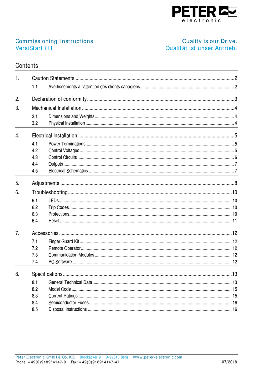
Peter electronic VersiStart i III Training manual

electronic
Quality is our Drive.
Commissioning Instructions
VS i III ... - 23 ... 1600

User Manual
VersiStart i III Quality is our Drive.
Qualität ist unser Antrieb.
Contents
1. About This Manual...............................................................................................................................3
2. Caution Statements .............................................................................................................................4
2.1 Electrical shock risk.......................................................................................................................................................................4
2.2 System Design and Safety of Personnel.......................................................................................................................................4
2.3 Disposal Instructions.....................................................................................................................................................................4
3. Avertissements à l'attention des clients canadiens..........................................................................5
4. Declaration of conformity....................................................................................................................6
5. Introduction..........................................................................................................................................7
5.1 Feature List ...................................................................................................................................................................................7
5.2 Specifications................................................................................................................................................................................7
6. Installation..........................................................................................................................................14
6.1 Physical Installation.....................................................................................................................................................................14
6.2 Control Terminals........................................................................................................................................................................14
6.3 Control Voltage............................................................................................................................................................................15
6.4 Control Wiring..............................................................................................................................................................................15
6.5 Relay Outputs..............................................................................................................................................................................15
6.6 Motor Thermistors.......................................................................................................................................................................15
6.7 Power Terminations....................................................................................................................................................................16
6.8 Power Input and Output Configurations......................................................................................................................................17
6.9 Schematic Diagrams...................................................................................................................................................................18
7. Power Circuits....................................................................................................................................19
7.1 Motor Connection........................................................................................................................................................................19
7.2 Bypass Contactor........................................................................................................................................................................22
7.3 Main Contactor............................................................................................................................................................................22
7.4 Circuit Breaker.............................................................................................................................................................................22
7.5 Earth Terminals...........................................................................................................................................................................22
7.6 Power Factor Correction.............................................................................................................................................................22
7.7 Power Supply Fuses...................................................................................................................................................................23
8. Operation............................................................................................................................................29
8.1 The Keypad.................................................................................................................................................................................29
8.2 Starter Status LEDs ....................................................................................................................................................................29
8.3 Displays.......................................................................................................................................................................................29
8.4 Start, Stop and Reset Commands..............................................................................................................................................31
8.5 Soft Start Methods.......................................................................................................................................................................31
8.6 Stop Methods..............................................................................................................................................................................34
8.7 Jog Operation..............................................................................................................................................................................36
8.8 Inside Delta Operation ................................................................................................................................................................37
9. Programming Menu ...........................................................................................................................38
9.1 Quick Setup.................................................................................................................................................................................39
9.2 Standard Menu............................................................................................................................................................................40
VersiStart i III 2
9.3 Extended Menu...........................................................................................................................................................................41
9.4 Parameter Descriptions...............................................................................................................................................................43
9.5 Adjustment Lock..........................................................................................................................................................................55
9.6 Access Code...............................................................................................................................................................................55
9.7 Setup Tools.................................................................................................................................................................................56
10. Logs Menu..........................................................................................................................................57
10.1 Trip Log.......................................................................................................................................................................................57
10.2 Event Log....................................................................................................................................................................................57
10.3 Performance Counters................................................................................................................................................................57
11. Application Examples........................................................................................................................58
11.1 Installation with Main Contactor..................................................................................................................................................58
11.2 Installation with Bypass Contactor..............................................................................................................................................59
11.3 Emergency Run Operation..........................................................................................................................................................60
11.4 Auxiliary Trip Circuit....................................................................................................................................................................61
11.5 DC Brake with External Zero Speed Sensor...............................................................................................................................62
11.6 Soft Braking.................................................................................................................................................................................63
11.7 Two Speed Motor........................................................................................................................................................................64
12. Troubleshooting.................................................................................................................................65
12.1 Protection Responses.................................................................................................................................................................65
12.2 Trip Messages.............................................................................................................................................................................65
12.3 General Faults.............................................................................................................................................................................68
13. Accessories........................................................................................................................................70
13.1 Communication Modules.............................................................................................................................................................70
13.2 Remote Control Panel (RCP)......................................................................................................................................................70
13.3 Finger Guard Kit..........................................................................................................................................................................70
13.4 PC Software................................................................................................................................................................................70
14. Busbar Adjustment Procedure .........................................................................................................71

3 VersiStart i III
1. About This Manual
The examples and diagrams in this manual are included solely for illustrative purposes. The information contained in this manual is
subject to change at any time and without prior notice. In no event will responsibility or liability be accepted for direct, indirect or
consequential damages resulting from the use or application of this equipment.
WARNING
Indicates a hazard that may cause personal injury or death.
CAUTION
Indicates a hazard that may damage the equipment or installation.
NOTE
Provides helpful information.

VersiStart i III 4
2. Caution Statements
Caution Statements cannot cover every potential cause of equipment damage but can highlight common causes of damage. It is the
installer's responsibility to read and understand all instructions in this manual prior to installing, operating or maintaining the equipment,
to follow good electrical practice including applying appropriate personal protective equipment and to seek advice before operating this
equipment in a manner other than as described in this manual.
NOTE
The VersiStart i III soft starter is not user serviceable. The unit should only be serviced by authorised service
personnel. Unauthorised tampering with the unit will void the product warranty.
2.1 Electrical shock risk
The voltages present in the following locations can cause severe electric shock and may be lethal:
xAC supply cables and connections
xOutput cables and connections
xMany internal parts of the starter, and external option units
The AC supply must be disconnected from the starter using an approved isolation device before any cover is removed from the starter or
before any servicing work is performed.
WARNING - ELECTRICAL SHOCK HAZARD
Models VS i III 500~VS i III 1600N: The busbar and heatsink must be treated as live whenever the unit has mains voltage
connected (including when the starter is tripped or waiting for a command).
SHORT CIRCUIT
The VersiStart i III is not short circuit proof. After severe overload or short circuit, the operation of the VersiStart i III should
be fully tested by an authorised service agent.
GROUNDING AND BRANCH CIRCUIT PROTECTION
It is the responsibility of the user or person installing the VersiStart i III to provide proper grounding and branch circuit
protection according to local electrical safety codes.
2.2 System Design and Safety of Personnel
The starter is intended as a component for professional incorporation into complete equipment or a system. If installed incorrectly, the
starter may present a safety hazard.
The starter uses high voltages and currents, carries stored electrical energy, and is used to control equipment which can cause injury.
Close attention is required to the electrical installation and the system design to avoid hazards either in normal operation or in the event
of equipment malfunction. System design, installation, commissioning and maintenance must be carried out by personnel who havethe
necessary training and experience. They must read this safety information and this guide carefully.
None of the starter functions must be used to ensure safety of personnel, ie they must not be used for safety-related functions.
Careful consideration must be given to the functions of the starter which might result in a hazard, either through their intended behaviour
or through incorrect operation due to a fault. In any application where a malfunction of the starter or its control system could lead to or
allow damage, loss or injury, a risk analysis must be carried out, and where necessary, further measures taken to reduce the risk.
The system designer is responsible for ensuring that the complete system is safe and designed correctly according to the relevant safety
standards.
2.2.1 STOP function
The STOP function does not remove dangerous voltages from the starter, the motor or any external option units.
2.3 Disposal Instructions
Equipment containing electrical components may not be disposed of together with domestic waste.
It must be collected separately as electrical and electronic waste according to local and currently valid
legislation.

5 VersiStart i III
3. Avertissements à l'attention des clients canadiens
AVERTISSEMENT
L'icône AVERTISSEMENT ci-contre signale les informations concernant des risques pouvant entraîner des blessures
graves, voire mortelles. Pour votre sécurité, veuillez consulter les avertissements sur cette page ou demander une copie
du présent manuel en français auprès de votre distributeur local.
AVERTISSEMENT – RISQUE DE CHOC ÉLECTRIQUE
Les zones suivantes sont soumises à des tensions pouvant provoquer des risques de chocs électriques graves, voire
mortels :
Raccordement et câbles d'alimentation AC
Câbles et raccordements de sortie
De nombreuses pièces internes du démarreur
L'alimentation AC doit être déconnectée du démarreur au moyen d'un dispositif d'isolation agréé avant de retirer des
capots ou avant de procéder à des travaux d'entretien.
Modèles VS i III 500 à VS i III 1600N : Les barres de puissance et le radiateur doivent être traités comme étant des
éléments sous tension si l'appareil est relié au secteur (y compris lorsque le démarreur s'est mis en sécurité ou s'il attend
une commande).
PAR SÉCURITÉ
La fonction STOP du démarreur progressif n'isole pas des tensions dangereuses de la sortie du démarreur. Le
démarreur progressif doit être déconnecté par un dispositif d'isolement électrique approprié avant d'accéder aux
connexions électriques.
Les fonctions de protection du démarreur progressif ne concernent que la protection du moteur. Il relève de la
responsabilité de l'utilisateur d'assurer la sécurité des personnes travaillant sur les machines.
Le démarreur progressif est un appareil conçu pour s'intégrer dans un système électrique ; il relève donc de la
responsabilité du concepteur ou de l'utilisateur de veiller à ce que ce système soit sûr et conçu selon les normes de
sécurité locales en vigueur.
AVERTISSEMENT – DÉMARRAGES ACCIDENTELS
Dans certaines installations, des démarrages accidentels peuvent provoquer un risque supplémentaire pour la sécurité des
personnes ou endommager les machines contrôlées. Dans de tels cas, il est recommandé de doter l'alimentation du
démarreur progressif d'un interrupteur d'isolement et d'un coupe-circuit (par exemple, un disjoncteur) contrôlable à partir
d'un système de sécurité externe (par exemple, un arrêt d'urgence, un détecteur de défaut).
AVERTISSEMENT – LE DÉMARREUR PEUT DÉMARRER OU S'ARRÊTER À TOUT MOMENT
Le démarreur progressif répond aux commandes de contrôle de différentes origines et peut par conséquent démarrer ou
s'arrêter à tout moment. Toujours déconnecter le démarreur de la tension secteur avant d'accéder au démarreur ou à la
charge.
AVERTISSEMENT
Le bouton STOP (ARRET) du clavier est toujours actif. Lors de l'utilisation d'une commande à distance 2 fils, le démarreur
progressif redémarrera si les entrées de démarrage/arrêt et de reset sont toujours actives.
AVERTISSEMENT – DÉCONNECTER L'ALIMENTATION PRINCIPALE AVANT D'ACCÉDER AU DÉMARREUR OU À
LA CHARGE
Le démarreur progressif comporte des protections intégrées qui peuvent déclencher des mises en sécurité dans
l'éventualité de défauts et ainsi arrêter le moteur. Des fluctuations de tension, des coupures d'alimentation et des blocages
du moteur peuvent produire des mises en sécurité de celui-ci.
Le moteur pourrait redémarrer une fois que les causes de l'arrêt ont été résolues, ce qui pourrait mettre en danger le
personnel. Toujours déconnecter le démarreur de la tension secteur avant d'accéder au démarreur ou à la charge.
AVERTISSEMENT
Ne pas appliquer la tension du secteur au démarreur tant que tout le câblage n'est pas terminé.
AVERTISSEMENT
Toujours appliquer la tension de commande avant (ou en même temps que) la tension secteur.
AVERTISSEMENT
Lors du raccordement du VersiStart i III en connexion 6 fils, toujours installer un contacteur principal ou un disjoncteur
magnéto-thermique à bobine de déclenchement.

VersiStart i III 6
4. Declaration of conformity
In industrial linguistic usage the drive controllers of the type series VersiStart i III are called "devices", however, in the sense of the "law
on the safety of equipment", the "EMC-law" or the "EC-machinery directive" they are not devices or machines ready for use or
connection but they are components. It is only possible to define their final function, when these components are integrated into the
design and construction of the user.
To be able to use the devices to their intended purpose, it requires power supply networks according to DIN EN 50160 (IEC
60038).
The user takes the responsibility that the user's design and construction comply with the applicable legal provisions.
The commissioning is strictly forbidden as long as the conformity of the final system with the guidelines 2006/42/EC (Machinery
directive) and 2014/35/EU (Low voltage directive) is not proved.
The devices of the VersiStart i III series are electrical equipment that is used in industrial electrical power installations. They are
designed for application in machines, in order to reduce the starting torque and starting current peaks as well as the tripping torque of
drives with three-phase induction motors. With due regard to the installation guidelines they meet the following requirements:
Emitted interference: Continuous duty EN 61000-6-3:2005
Acceleration, decel. EN 60947-4-2
Immunity to interference: EN 61000-6-2:2005
VersiStart i III has been designed to meet the standards specified in EN 60947-4-2: Ed2.2 2007-02 Low voltage switchgear – Part 4-2
Contactors and motor-starters – AC Semiconductor motor controllers and starters, for low voltage safety, operation and EMC.
This product has been designed as Class A equipment. Use of this product in domestic environments may cause radio interference, in
which case the user may be required to employ additional mitigation methods.
Dr. Thomas Stiller
Managing director

7 VersiStart i III
5. Introduction
5.1 Feature List
Extensive starting and stopping options
xAdaptive Control
xConstant Current
xCurrent Ramp
xTimed voltage ramp soft stop
xBrake
Models for allconnection requirements
x23 A to 1600 A (nominal)
x200 VAC to 525 VAC
x380 VAC to 690 VAC
xInternally bypassed options
xIn-line or inside delta connection (auto-detect)
Inputs and outputs
xRemote control inputs
(3 x fixed, 1 x programmable)
xRelay outputs
(3 x programmable)
xAnalog output
xCommunication modules: Ethernet (Profinet, Modbus TCP,
Ethernet/IP), Profibus, DeviceNet, Modbus RTU, and USB
Easy-to-read display with comprehensive feedback
xMulti-language feedback
xMultiple status screens and performance graphs
xDate and time stamped event logging
xOperational counters (number of starts, hours-run, kWh)
xPerformance monitoring (current, voltage, power factor, kWh)
xUser-programmable monitoring screen
Customisable protection
xMotor overload
xExcess Start Time
xUndercurrent
xInstantaneous overcurrent
xCurrent imbalance
xMains frequency
xInput Trip
xMotor thermistor
xPower circuit
xPhase sequence
5.2 Specifications
5.2.1 Model Code
VS i III – –
Control voltage
C1 = 110~120 VAC or 220~240 VAC
C2 = 24 VAC/VDC
Bypass
" " = internally bypassed
N = non-bypassed
Nominal current rating
Mains voltage
525 = 200 ~ 525 VAC
690 = 380 ~ 690 VAC
5.2.2 Current Ratings
Contact your local supplier for ratings under operating conditions not covered by these ratings charts.
Current Ratings for Bypass Operation
80 A : AC-53b 3.5 - 15 : 345
Off time (seconds)
Start time (seconds)
Start current (multiple of motor full load current)
Starter current rating (amperes)
NOTE
Models VS i III 255N~VS i III 1600N must be externally bypassed.

VersiStart i III 8
In-line connection
AC53b 3.0-10:350
40 ºC <1000 metres AC53b 3.5-15:345
40 ºC <1000 metres AC53b 4.0-20:340
40 ºC <1000 metres AC53b 4.5-30:330
40 ºC <1000 metres
VS i III 23 23 A 20 A 17 A 15 A
VS i III 43 43 A 37 A 31 A 26 A
VS i III 50 50 A 44 A 37 A 30 A
VS i III 53 53 A 53 A 46 A 37 A
AC53b 3.0-10:590
40 ºC <1000 metres AC53b 3.5-15:585
40 ºC <1000 metres AC53b 4.0-20:580
40 ºC <1000 metres AC53b 4.5-30:570
40 ºC <1000 metres
VS i III 76 76 A 64 A 55 A 47 A
VS i III 97 97 A 82 A 69 A 58 A
VS i III 100 100 A 88 A 74 A 61 A
VS i III 105 105 A 105 A 95 A 78 A
VS i III 145 145 A 123 A 106 A 90 A
VS i III 170 170 A 145 A 121 A 97 A
VS i III 200 200 A 189 A 160 A 134 A
VS i III 220 220 A 210 A 178 A 158 A
VS i III 255 255 A 231 A 201 A 176 A
VS i III 255N 255 A 231 A 201 A 176 A
VS i III 350 350 A 329 A 284 A 244 A
VS i III 360N 360 A 360 A 310 A 263 A
VS i III 380N 380 A 380 A 359 A 299 A
VS i III 425 425 A 411 A 355 A 305 A
VS i III 430N 430 A 430 A 368 A 309 A
VS i III 500 500 A 445 A 383 A 326 A
VS i III 580 580 A 492 A 425 A 364 A
VS i III 620N 620 A 620 A 540 A 438 A
VS i III 650N 650 A 650 A 561 A 455 A
VS i III 700 700 A 592 A 512 A 438 A
VS i III 790N 790 A 790 A 714 A 579 A
VS i III 820 820 A 705 A 606 A 516 A
VS i III 920 920 A 804 A 684 A 571 A
VS i III 930N 930 A 930 A 829 A 661 A
VS i III 1000 1000 A 936 A 796 A 664 A
VS i III 1200N 1200 A 1200 A 1200 A 1071 A
VS i III 1410N 1410 A 1410 A 1319 A 1114 A
VS i III 1600N 1600 A 1600 A 1600 A 1353 A
Inside delta connection
AC53b 3.0-10:350
40 ºC <1000 metres AC53b 3.5-15:345
40 ºC <1000 metres AC53b 4.0-20:340
40 ºC <1000 metres AC53b 4.5-30:330
40 ºC <1000 metres
VS i III 23 34 A 30 A 26 A 22 A
VS i III 43 64 A 59 A 51 A 44 A
VS i III 50 75 A 66 A 55 A 45 A
VS i III 53 80 A 80 A 69 A 55 A
AC53b 3.0-10:590
40 ºC <1000 metres AC53b 3.5-15:585
40 ºC <1000 metres AC53b 4.0-20:580
40 ºC <1000 metres AC53b 4.5-30:570
40 ºC <1000 metres
VS i III 76 114 A 96 A 83 A 70 A
VS i III 97 145 A 123 A 104 A 87 A
VS i III 100 150 A 132 A 112 A 92 A
VS i III 105 157 A 158 A 143 A 117 A
VS i III 145 218 A 184 A 159 A 136 A
VS i III 170 255 A 217 A 181 A 146 A
VS i III 200 300 A 283 A 241 A 213 A
VS i III 220 330 A 315 A 268 A 238 A
VS i III 255 382 A 346 A 302 A 264 A
VS i III 255N 382 A 346 A 302 A 264 A
VS i III 350 525 A 494 A 427 A 366 A
VS i III 360N 540 A 540 A 465 A 395 A

9 VersiStart i III
VS i III 380N 570 A 570 A 539 A 449 A
VS i III 425 638 A 617 A 533 A 458 A
VS i III 430N 645 A 645 A 552 A 464 A
VS i III 500 750 A 668 A 575 A 490 A
VS i III 580 870 A 738 A 637 A 546 A
VS i III 620N 930 A 930 A 810 A 651 A
VS i III 650N 975 A 975 A 842 A 683 A
VS i III 700 1050 A 889 A 768 A 658 A
VS i III 790N 1185 A 1185 A 1075 A 868 A
VS i III 820 1230 A 1058 A 910 A 774 A
VS i III 920 1380 A 1206 A 1026 A 857 A
VS i III 930N 1395 A 1395 A 1244 A 992 A
VS i III 1000 1500 A 1404 A 1194 A 997 A
VS i III 1200N 1800 A 1800 A 1800 A 1606 A
VS i III 1410N 2115 A 2115 A 1979 A 1671 A
VS i III 1600N 2400 A 2400 A 2400 A 2030 A
Current Ratings for Continuous Operation (Not bypassed)
351 A : AC-53a 3.5 - 15 : 50 - 6
Starts per hour
On-load duty cycle (%)
Start time (seconds)
Start current (multiple of motor full load current)
Starter current rating (amperes)
In-line connection
AC53a 3-10:50-6
40 ºC <1000 metres AC53a 3.5-15:50-6
40 ºC <1000 metres AC53a 4-20:50-6
40 ºC <1000 metres AC53a 4.5-30:50-6
40 ºC <1000 metres
VS i III 255N 255 A 222 A 195 A 171 A
VS i III 360N 360 A 351 A 303 A 259 A
VS i III 380N 380 A 380 A 348 A 292 A
VS i III 430N 430 A 413 A 355 A 301 A
VS i III 620N 620 A 614 A 515 A 419 A
VS i III 650N 650 A 629 A 532 A 437 A
VS i III 790N 790 A 790 A 694 A 567 A
VS i III 930N 930 A 930 A 800 A 644 A
VS i III 1200N 1200 A 1200 A 1135 A 983 A
VS i III 1410N 1410 A 1355 A 1187 A 1023 A
VS i III 1600N 1600 A 1600 A 1433 A 1227 A
Inside delta connection
AC53a 3-10:50-6
40 ºC <1000 metres AC53a 3.5-15:50-6
40 ºC <1000 metres AC53a 4-20:50-6
40 ºC <1000 metres AC53a 4.5-30:50-6
40 ºC <1000 metres
VS i III 255N 382 A 334 A 293 A 257 A
VS i III 360N 540 A 527 A 455 A 388 A
VS i III 380N 570 A 570 A 522 A 437 A
VS i III 430N 645 A 620 A 533 A 451 A
VS i III 620N 930 A 920 A 773 A 628 A
VS i III 650N 975 A 943 A 798 A 656 A
VS i III 790N 1185 A 1185 A 1041 A 850 A
VS i III 930N 1395 A 1395 A 1200 A 966 A
VS i III 1200N 1800 A 1800 A 1702 A 1474 A
VS i III 1410N 2115 A 2033 A 1780 A 1535 A
VS i III 1600N 2400 A 2400 A 2149 A 1840 A

VersiStart i III 10
Minimum and Maximum Current Settings
The VersiStart i III's minimum and maximum full load current settings depend on the model:
In-line connection Inside delta connection
Model Minimum Maximum Minimum Maximum
VS i III 23 5 A 23 A 5 A 34 A
VS i III 43 9 A 43 A 9 A 64 A
VS i III 50 10 A 50 A 10 A 75 A
VS i III 53 11 A 53 A 11 A 79 A
VS i III 76 15 A 76 A 15 A 114 A
VS i III 97 19 A 97 A 19 A 145 A
VS i III 100 20 A 100 A 20 A 150 A
VS i III 105 21 A 105 A 21 A 157 A
VS i III 145 29 A 145 A 29 A 217 A
VS i III 170 34 A 170 A 34 A 255 A
VS i III 200 40 A 200 A 40 A 300 A
VS i III 220 44 A 220 A 44 A 330 A
VS i III 255 51 A 255 A 51 A 382 A
VS i III 255N 51 A 255 A 51 A 382 A
VS i III 350 70 A 350 A 70 A 525 A
VS i III 360N 72 A 360 A 72 A 540 A
VS i III 380N 76 A 380 A 76 A 570 A
VS i III 425 85 A 425 A 85 A 638 A
VS i III 430N 86 A 430 A 86 A 645 A
VS i III 500 100 A 500 A 100 A 750 A
VS i III 580 116 A 580 A 116 A 870 A
VS i III 620N 124 A 620 A 124 A 930 A
VS i III 650N 130 A 650 A 130 A 975 A
VS i III 700 140 A 700 A 140 A 1050 A
VS i III 790N 158 A 790 A 158 A 1185 A
VS i III 820 164 A 820 A 164 A 1230 A
VS i III 920 184 A 920 A 184 A 1380 A
VS i III 930N 186 A 930 A 186 A 1395 A
VS i III 1000 200 A 1000 A 200 A 1500 A
VS i III 1200N 240 A 1200 A 240 A 1800 A
VS i III 1410N 282 A 1410 A 282 A 2115 A
VS i III 1600N 320 A 1600 A 320 A 2400 A
5.2.3 Specifications
Supply
Mains voltage (L1, L2, L3)
525 .............................................................................................................................................................. 200 ~ 525 VAC (± 10%)
690 ...................................................................................................... 380 ~ 600 VAC (± 10%) (in-line or inside delta connection)
690 ....................................................................................................... 380 ~ 690 VAC (± 10%) (earthed star supply system only)
Control voltage (A4, A5, A6)
C1 ......................................................................................................... 110 ~ 120 VAC or 220 ~ 240 VAC (+ 10% / -15%), 600mA
C2 ............................................................................................................................................................. 24 VAC/VDC ±20%, 2.8A
Mains frequency ................................................................................................................................................................. 45 Hz ~ 66 Hz
Rated insulation voltage to earth ................................................................................................................................................. 600 VAC
Rated impulse withstand voltage ........................................................................................................................................................ 4 kV
Form designation ...................................................................................... Bypassed or continuous, semiconductor motor starter form 1
Short circuit capability
Coordination with semiconductor fuses............................................................................................................................................. Type 2
Coordination with HRC fuses............................................................................................................................................................. Type 1
VS i III 23 ~ VS i III 220 ............................................................................................................................ prospective current 65 kA
VS i III 255 ~ VS i III 1000 ........................................................................................................................ prospective current 85 kA
VS i III 255N ~ VS i III 930N .................................................................................................................... prospective current 85 kA
VS i III 1200N ~ VS i III 1600N .............................................................................................................. prospective current 100 kA

11 VersiStart i III
Electromagnetic capability (compliant with EU Directive 2014/35/EU)
EMC Emissions ........................................................................................ IEC 60947-4-2 Class B and Lloyds Marine No 1 Specification
EMC Immunity ....................................................................................................................................................................... IEC 60947-4-2
Inputs
Input rating ................................................................................................................................................... Active 24 VDC, 8 mA approx
Start (54, 55) ...................................................................................................................................................................... Normally Open
Stop (56, 57) .................................................................................................................................................................... Normally Closed
Reset (58, 57) .................................................................................................................................................................. Normally Closed
Programmable input (53, 55) ............................................................................................................................................. Normally Open
Motor thermistor (64, 65) .............................................................................................................................. Trip >3.6 k:, reset <1.6 k:
Outputs
Relay outputs ....................................................................................................... 10A @ 250 VAC resistive, 5A @ 250 VAC AC15 pf 0.3
Programmable outputs
Relay A (13, 14) ..................................................................................................................................................... Normally Open
Relay B (21, 22, 24) ..................................................................................................................................................... Changeover
Relay C (33, 34) .......................................................................................................................................................... Normally Open
Analog output (40, 41) ........................................................................................................................... 0-20 mA or 4-20 mA (selectable)
Maximum load .......................................................................................................................................... 600 :(12 VDC @ 20 mA)
Accuracy ................................................................................................................................................................................... ± 5%
24 VDC output (55, 41)
Maximum load.......................................................................................................................................................................... 200 mA
Accuracy ................................................................................................................................................................................. ± 10%
Environmental
Protection
VS i III 23 ~ VS i III 105 .............................................................................................................................................................. IP20
VS i III 145 ~ VS i III 1600N ........................................................................................................................................................ IP00
Operating temperature............................................................................................................. -Û&WRÛ& DERYHÛ&ZLWKGHUDWLQJ
Storage temperature ...................................................................................................................................................... -25 °C to + 60 °C
Operating Altitude ....................................................................................................................... 0 - 1000 m, above 1000 m with derating
Humidity ....................................................................................................................................................... 5% to 95% Relative Humidity
Pollution degree ............................................................................................................................................................ Pollution Degree 3
Vibration (VS i III 23 ~ VS i III 1000) ................................................................................................................................. IEC 60068-2-6
Heat Dissipation
During Start .............................................................................................................................................................. 4.5 watts per ampere
During Run
VS i III 23 ~ VS i III 53 ........................................................................................................................................... ZDWWVDSSUR[
VS i III 76 ~ VS i III 105 ........................................................................................................................................ ZDWWVDSSUR[
VS i III 145 ~ VS i III 220 .................................................................................................................................... ZDWWVDSSUR[
VS i III 255 ~ VS i III 500 ........................................................................................................................................ZDWWVDSSUR[
VS i III 580 ~ VS i III 1000 ......................................................................................................................................ZDWWVapprox
VS i III 255N ~ VS i III 1600N ............................................................................................................. 4.5 watts per ampere approx
Certification
CE ........................................................................................................................................................................................ EN 60947-4-2
RoHS ........................................................................................................................................ Compliant with EU Directive 2011/65/EU
UL / C-UL ........................................................................................................................................................................................ UL 508*
VS i III 23 ~ VS i III 425, VS i III 255N ~ VS i III 1600N ........................................................................................................ UL Listed
VS i III 500 ~ VS i III 1000 ........................................................................................................................................... UL Recognised
VS i III 23 ~ VS i III 105 ..................................................................................................................IP20 & NEMA1, UL Indoor Type 1
VS i III 145 ~ VS i III 1600N .................................................................................................................. IP00, UL Indoor Open Type
................................................................................................................................. IP20, when fitted with optional finger guard kit
Marine (VS i III 23 ~ VS i III 1000, internally bypassed models only) .............................................................................................................
Lloyds ............................................................................................................................................ Lloyds Marine No 1 Specification
* For UL certification additional requirements may apply, depending on the models. For details, refer to UL Compliant Installation on
page 12.

VersiStart i III 12
5.2.4 UL Compliant Installation
This section details additional requirements and configuration settings for the VersiStart i III soft starters to be UL-compliant. Refer to UL
Fuse Selection and Short Circuit Ratings on page 27.
Models VS i III 23 ~ VS i III 105
There is no additional requirement for these models.
Models VS i III 145 ~ VS i III 425, VS i III 255N ~ VS i III 1600N
Use the recommended pressure terminal/connector kit. Refer to Terminal/Connector Parts on page 12 for more information.
Models VS i III 500 ~ VS i III 1000
These models are UL recognised components. Separate cable landing busbars may be required within the electrical cabinet when
terminating cables sized according to the National Wiring Code (NEC) regulations.
Terminal/Connector Parts
For models VS i III 145~VS i III 425 and VS i III 255N~VS i III 1600N to be UL compliant, you must use the recommended pressure
terminal/connector as detailed in the table below.
Models FLC (A) No. of wires Recommended lugs part No.
VS i III 145 145 1 OPHD 95-16
VS i III 170 170 1 OPHD 120-16
VS i III 200 200 1 OPHD 150-16
VS i III 220 220 1 OPHD 185-16
VS i III 255 255 1 OPHD 240-20
VS i III 350 350 1 OPHD 400-16
VS i III 425 425 2 OPHD 185-16
VS i III 255N 255 1 OPHD 240-20
VS i III 360N 360
2 1 x 600T-2
VS i III 380N 380
VS i III 430N 430
VS i III 620N 620
VS i III 650N 650
VS i III 790N 790 4 2 x 600T-2
VS i III 930N 930 3 2 x 600T-2
VS i III 1200N 1200 4 1 x 750T-4
VS i III 1410N 1410
VS i III 1600N 1600 5 1 x 750T-4
1 x 600T-3

13 VersiStart i III
5.2.5 Dimensions and Weights
C
A
B
D
E
C D
A
B
E
08718.G
Width
mm (inch) Height
mm (inch) Depth
mm (inch) Weight
kg (lb)
Model A B C D E
VS i III 23
VS i III 43
183 4.1
VS i III 50
(7.2) (9.0)
VS i III 53 150 124 295 278
VS i III 76 (5.9) (4.9) (11.6) (10.9) 4.4 (9.7)
VS i III 97
213 4.9
VS i III 100
(8.4) (10.8)
VS i III 105
VS i III 145
13.6 (30.0)
VS i III 170 275 250 438 380 248 13.8 (30.4)
VS i III 200 (10.8) (9.8) (17.2) (15.0) (9.8) 14.6
VS i III 220
(32.2)
VS i III 255 424 376 440 392 296 26 (57.3)
VS i III 350 (16.7) (14.8) (17.3) (15.4) (11.7) 29.4
VS i III 425
(64.8)
VS i III 500 49
VS i III 580
(108.0)
VS i III 700 433 320 640 600 293 62.5
VS i III 820 (17.0) (12.6) (25.2) (23.6) (11.5) (137.8)
VS i III 920 63
VS i III 1000
(138.9)
VS i III 255N 390 (15.4) 320 (12.6) 460 (18.1) 400 (15.7) 278 (10.9) 23 (50.7)
VS i III 360N
VS i III 380N 36
VS i III 430N
(79.4)
VS i III 620N 430 320 689 522 301
VS i III 650N (16.9) (12.6) (27.1) (20.6) (11.9) 39.5
VS i III 790N
(87.1)
VS i III 930N
51.5 (113.5)
VS i III 1200N 574 500 860 727 362 128.5 (283.3)
VS i III 1410N (22.6) (19.7) (33.9) (28.6) (14.3) 130 (286.6)
VS i III 1600N
140 (308.6)

VersiStart i III 14
6. Installation
6.1 Physical Installation
1
4
3
2
2
1/L1 5/ L3
3/ L 2
2/T1 6/T3
4/ T 2
1/L1 5/ L33/ L 2
2/T1 6/ T3
4/ T 2
B
1/L15/L3
3/L2
2/T16/T3
4/T2
1/L15/L33/L2
1 VS i III 23 ~ VS i III 220: Allow 100 mm (3.94 inches)
between soft starters.
VS i III 255 ~ VS i III 1000: Allow 200 mm (7.88 inches)
between soft starters.
VS i III 255N: Allow 100 mm (3.94 inches) between soft
starters.
VS i III 360N ~ VS i III 1600N: Allow 200 mm (7.88 inches)
between soft starters.
2 VS i III 23 ~ VS i III 220: Allow 50 mm (1.97 inches)
between the soft starter and solid surfaces.
VS i III 255 ~ VS i III 1000: Allow 200 mm (7.88 inches)
between the soft starter and solid surfaces.
VS i III 255N: Allow 100 mm (3.94 inches) between the
soft starter and solid surfaces.
VS i III 360N ~ VS i III 1600N: Allow 200 mm (7.88 inches)
between the soft starter and solid surfaces.
3 Soft starters may be mounted side by side with no
clearance (that is, if mounted without communications
modules).
4 The soft starter may be mounted on its side. Derate the
soft starter's rated current by 15%.
6.2 Control Terminals
Control terminations use 2.5mm2plug-in terminal blocks. Unplug each block, complete the wiring, then reinsert the block.
13 1421 22 24 33 34
40 41 53 5455 56 57 58 64 65A4 A5 A6
54321
9876
A4 A5 A6 40 41 53 54 55 56 57 58 64 65
13 14 21 22 24 33 34
13 14 21 22 24 33 34
40 41 5354 5556 5758 64 65
A4 A5 A6
54321
9876
54321
9876
1
2
3
4
1
2
3
4
1 Relay outputs 4 Inputs and outputs
13, 14 Relay output A (default = Main Contactor) 54, 55 Start
21, 22, 24 Relay output B (default = Run) 56, 57 Stop
33, 34 Relay output C (default = Trip) 58, 57 Reset
2 Control voltage (model dependent) 53, 55 Programmable input A
(default = Motor Set Select)
A5, A6 110~120 VAC 64, 65 Motor thermistor input
A4, A6 220~240 VAC 40, 41 Analog output
A5, A6 24 VAC/VDC 55, 41 24 VDC output
3 DB9 connector for remote control panel
NOTE
If you are not using a thermistor, do not short terminals 64, 65.
NOTE
The DB9 connector on the soft starter should only be used to connect to a remote control panel. Connecting other
equipment to this port can damage the soft starter or the equipment.

15 VersiStart i III
6.3 Control Voltage
Different models require control voltage to different terminals:
xC1 (110~120 VAC) A5, A6
xC1 (220~240 VAC) A4, A6
xC2 (24 VAC/VDC) A5, A6
6.4 Control Wiring
The VersiStart i III has three fixed inputs for remote control. These inputs should be controlled by contacts rated for low voltage, low
current operation (gold flash or similar).
1
A
B
AB
C
A
B
C
C
23
C32
C31
C24
C23
C42
C41
03943.D
C32
C31
C24
C23
C42
C41
C32
C31
C24
C23
C42
C41
1 Two-wire control
2 Three-wire control
3 Four-wire control
A Start
B Stop
C Reset
CAUTION
The control inputs are powered by the soft starter. Do not apply external voltage to the control input terminals.
Cables to the control inputs must be segregated from mains voltage and motor cabling.
6.5 Relay Outputs
The VersiStart i III has three programmable relay outputs.
Operation of the programmable outputs is determined by the settings of parameters 7A~7I.
xIf assigned to Main Contactor, the output activates as soon as the soft starter receives a start command and remains active
while the soft starter is controlling the motor (until the motor starts a coast to stop, or until the end of a soft stop).
xIf assigned to Run, the output activates when the soft start is complete (when the starting current falls below 120% of the
programmed motor full load current) and remains closed until the beginning of a stop (either soft stop or coast to stop).
xIf assigned to a trip function, the output activates when a trip occurs.
xIf assigned to a flag, the output activates when the specified flag is active (parameters 7J~7L).
CAUTION
Some electronic contactor coils are not suitable for direct switching with PCB mount relays. Consult the contactor
manufacturer/supplier to confirm suitability.
6.6 Motor Thermistors
Motor thermistors can be connected directly to the VersiStart i III. The soft starter will trip when the resistance of the thermistor circuit
exceeds approximately 3.6 k:or falls below 20 :.
If no motor thermistors are connected to the VersiStart i III thermistor input terminals 64, 65 must be open. If 64, 65 are shorted, the
VersiStart i III will trip.
The thermistor input is disabled by default, but activates automatically when a thermistor is detected. If thermistors have previously been
connected to the VersiStart i III but are no longer required, either:
xconnect a 1.2 k:resistor between 64, 65 or
xreset the starter to factory defaults (refer to Load/Save Settings). If you wish to retain the starter’s configuration, save the
starter’s settings to a user set before resetting. Reload the settings after the thermistor input has been reset.
NOTE
The thermistor circuit should be run in screened cable and must be electrically isolated from earth and all other power and
control circuits.

VersiStart i III 16
6.7 Power Terminations
NOTE
For personnel safety, the power terminals on models up to VS i III 105 are protected by snap-off tabs. When using large
cables, it may be necessary to break off these tabs.
NOTE
Some units use aluminium busbars. When connecting power terminations, we recommend cleaning the surface contact
area thoroughly (using an emery or stainless steel brush) and using an appropriate jointing compound to prevent corrosion.
Use only copper stranded or solid conductors, rated for 75 ºC or higher.
VS i III 23~VS i III 105
05966.E
Cable size:
6-50 mm2(AWG 10-1/0)
Torque: 4 Nm (2.9 ft-lb)
1 1290 .A
14 mm (0.55 inch)
Torx T20 x 150
Flat 7 mm x 150
VS i III 145 VS i III 170~VS i III 220 VS i III 255
19 Nm (14.0 ft-lb) 38 Nm (28.0 ft-lb) 38 Nm (28.0 ft-lb)
6mm
19 mm
8.5 mm
(M8)
08351.B
08352.B
6mm19 mm
10.5 mm
(M10)
5m
m
28 mm
11 mm
(M10)
13181.B
VS i III 350~VS i III 425 VS i III 500~VS i III 1000 VS i III 255N
38 Nm (28.0 ft-lb) 38 Nm (28.0 ft-lb) 38 Nm (28.0 ft-lb)
6mm
28 mm
11 mm
(M10)
14543.A
13 mm
32 mm
11 mm
(M10)
09866.B
6mm
32 mm
10.5 mm
(M10)
08353.B
VS i III 360N~VS i III 930N VS i III 1200N~VS i III 1600N
38 Nm (28.0 ft-lb) 66 Nm (48.7 ft-lb)
13 mm32 mm
10.5 mm
(M10)
08354.B
16 mm51 mm
12.5 mm
(M12)
08355.B

17 VersiStart i III
6.8 Power Input and Output Configurations
6.8.1 Internally Bypassed Models (VS i III 23~VS i III 1000)
Models VS i III 23 ~ VS i III 220 have power inputs at the top of the unit and outputs at the bottom of the unit.
Internally bypassed models VS i III 255 ~ VS i III 425 have output busbars at the bottom of the unit and input busbars at both the top and
bottom of the unit. The AC supply can be connected 'Top in, Bottom out' or 'Bottom in, Bottom out'.
Internally bypassed models VS i III 500 ~ VS i III 1000 have input and output busbars at the top and bottom of the unit. The AC supply
can be connected 'Top in, Bottom out', 'Top in, Top out', 'Bottom in, Bottom out' or 'Bottom in, Top out'.
VS i III 23~
VS i III 105 VS i III 145~
VS i III 220 VS i III 255~
VS i III 425 VS i III 500~
VS i III 1000
1/L1, 3/L2, 5/L3
2/T1, 4/T2, 6/T3
1/L1 3/L2 5/L3
2/T1 4/T2 6/T3
1/L1 3/L2 5/L3
2/T1 4/T2 6/T3
1/L1 3/L2 5/L3
2/T1 4/T2 6/T3
1/L1 3/L2 5/L3
1/L1 3/L2 5/L3
2/T1 4/T2 6/T3
15614.A
StatusGraphs Logs
Exit Enter
Menu
Local
Remote
Local
Ready
Run
Trip
Start
Reset
Stop
RemoteInputs
InputA S tart Stop R eset
Status Graphs Logs
Exit Enter
Menu
Local
Remote
Local
Ready
Run
Trip
Start
Reset
Stop
RemoteInputs
InputA S tart Stop Reset
StatusGraphs Logs
Exit Enter
Menu
Local
Remote
Local
Ready
Run
Trip
Start
Reset
Stop
RemoteInputs
InputA Start Stop Reset
StatusGraphs Logs
Exit Enter
Menu
Local
Remote
Local
Ready
Run
Trip
Start
Reset
Stop
RemoteInputs
InputA Start Stop Reset
6.8.2 Non-bypassed Model - VS i III 255N
VS i III 255N has dedicated bypass terminals at the bottom of the unit.
The bypass terminals are T1B, T2B, T3B.
15613.A
Status GraphsLogs
Exit Enter
Menu
Local
Remote
Loca l
Ready
Run
Trip
Start
Reset
Stop
RemoteInputs
InputA Start StopReset
1/L1 3/L2 5/L3
T1B T2B T3B
2/T1 4/T2 6/T3
6.8.3 Non-bypassed Models (VS i III 360N~VS i III 1600N)
VS i III 360N~VS i III 1600N have dedicated bypass terminals, on the input busbars. The bypass terminals are L1B, L2B, L3B.
The busbars on non-bypassed models VS i III 360N ~ VS i III 1600N can be adjusted for top or bottom input and output as required.
Refer to Busbar Adjustment Procedure for step-by-step instructions. All units are manufactured bottom in/bottom out.
(L1B L2B L3B)
1/L1 3/L2 5/L3
2/T1 4/T2 6/T3
1/L1 3/L2 5/L3
(L1B L2B L3B)
2/T1 4/T2 6/T3
(L1B L2B L3B)
1/L1 3/L2 5/L3
2/T1 4/T2 6/T3
1/L1 3/L2 5/L3
(L1B L2B L3B)
2/T1 4/T2 6/T3
08723.D

VersiStart i III 18
6.9 Schematic Diagrams
Internally bypassed models Non-bypassed models
22
21
6/T3
2/T1
13
14
4/T2
24
33
34
65
64
41
40
56
57
58
53
54
A6
A5
A4
5/L3
3/L2
55
PE
1/L1
24VDC
200 mA
08724.B
+
4
1
2
3
+
A
6/T3
2/T1
4/T2
5/L3
3/L2
1/L1
L3B
L2B
L1B
4
1
2
3
PE
55
A4
A5
A6
54
53
58
57
56
40
41
64
65
34
33
24
14
13
21
22
A
08725.B
*
*
*
+
+
24VDC
200 mA
1 Control voltage (model dependent) 54, 55 Start
2 Remote control inputs 56, 57 Stop
3 Motor thermistor input 58, 57 Reset
4 Relay outputs 53, 55 Programmable input A
(default = Motor Set Select)
40, 41 Analog output 13, 14 Relay output A (default = Main Contactor)
55, 41 24 VDC output 21, 22, 24 Relay output B (default = Run)
33, 34 Relay output C (default = Trip)
NOTE
Different models require control voltage to different terminals:
xC1 (110~120 VAC) A5, A6
xC1 (220~240 VAC) A4, A6
xC2 (24 VAC/VDC) A5, A6
NOTE
* VS i III 255N current transformers are located on the output. Bypass terminals are labelled T1B, T2B and T3B.

19 VersiStart i III
7. Power Circuits
7.1 Motor Connection
VersiStart i III soft starters can be connected to the motor in-line or inside delta (also called three-wire and six-wire connection). When
connecting in inside delta, enter the motor full load current (FLC) for parameter 1A. The VersiStart i III will automatically detect whether
the motor is connected in-line or inside delta and will calculate the correct inside delta current level.
7.1.1 Testing the Installation
The VersiStart i III can be connected to a small motor for testing. During this test, the soft starter's control input and relay output
protection settings can be tested. This test mode is not suitable for testing soft starting or soft stopping performance.
The FLC of the test motor must be at least 2% of the soft starter's minimum FLC (refer to Minimum and Maximum Current Settings on
page 10).
NOTE
When testing the soft starter with a small motor, set parameter 1A Motor Full Load Current to the minimum allowable value.
Models which are internally bypassed do not require an external bypass contactor.
7.1.2 In-line installation, internallybypassed
6/T3
2/T1
5/L3
3/L2
1/L1
13
14
4/T2
E
K1
K1 F1
M
3
K1 Main contactor (optional)
F1 Semiconductor fuses (optional)
13, 14 Relay output A (= Main Contactor,
default)
This manual suits for next models
32
Table of contents
Other Peter electronic Controllers manuals

Peter electronic
Peter electronic VS p III Series Training manual

Peter electronic
Peter electronic VersiStart p III Series Training manual

Peter electronic
Peter electronic VersiStart i II Training manual

Peter electronic
Peter electronic VB 230-6 L Training manual

Peter electronic
Peter electronic SGP 160-2,5 Training manual

Peter electronic
Peter electronic VersiStart II 3L Series Training manual