Petroline-A DPS -140 User manual

1
ы
DPS -140
Operation Manual
PLA 140.207.000.000RE
2019

2019
OPERATION MANUAL
2
This operation manual provides DPS-140 (Indicator) Position and Speed Sensor work
and its modifications. Document consists of information, which is necessary for the right, safe op-
eration and technical service. The manual consists of works’ description, layouts and instructions
necessary for the right preparation for mounting and its execution, commissioning and settings in a
complex of control module DL-140,DEL-150
To exclude the possibility of mechanical damage, violation of electroplating and paintwork,
it is necessary to follow the rules of storage and transportation of the device. While studying the
manual, it is necessary to follow technical specification and manual’s instruction of PC
DPS-140 еxploitation is allowed to be used by personnel who has studied this manual, set of
exploitation documentation and passed safety training.
ISO 9001:2015
RPE “Petroline-A” LLC quality management system is responded to ISO 9001:2015 re-
quirements in research, production and shipment of instrumentation for oil and gas industry; guar-
anty and post-guaranty service execution (Certificate of compliance№ 17.0497.026 from 13th of
March 2018 (Application1)).
Scope of certification of management system of RPE “Petroline-A” LLC
1.
Goods/services: research, production and shipment instrumentation for oil and gas
industry: guaranty and post-guaranty service execution.
2.
Release of product in compliance with ISO 9001:2015:
7.1
Planning of production release
7.2
Processes connected with a customer
7.3
Design and research
7.4
Purchasing
7.5
Production and maintenance support
7.6
Equipment management for monitoring and measurement.
3.
Exclusion from product life cycle processes: 7.5.2

DPS-140
PLA 140.207.000.000RE
3
1. Content
1. Description and work .................................................................................................................................... 5
1.1. DPS-140 Desription and work .................................................................................................................... 5
1.1.1. DPS-140 Purpose........................................................................................................................... 5
DPS-140 in a complex with DEL-140, DEL-150, DEL-150Еis designed to control of drawworks shaft
rotation of drilling and workover rigs.............................................................................................................. 5
1.1.2. DPS-140 Modifications and its technical characteristics:................................................................. 5
Table 1 –Main technical characteristics and DPS-140(А,E) parameters.......................................................... 5
Table 2 –Main technical characteristics and parameters DPS-140(I)............................................................... 5
Table 3-Main technical characteristics and parameters DPS-140(P)................................................................. 5
Table 4–Dimensions, weight ......................................................................................................................... 6
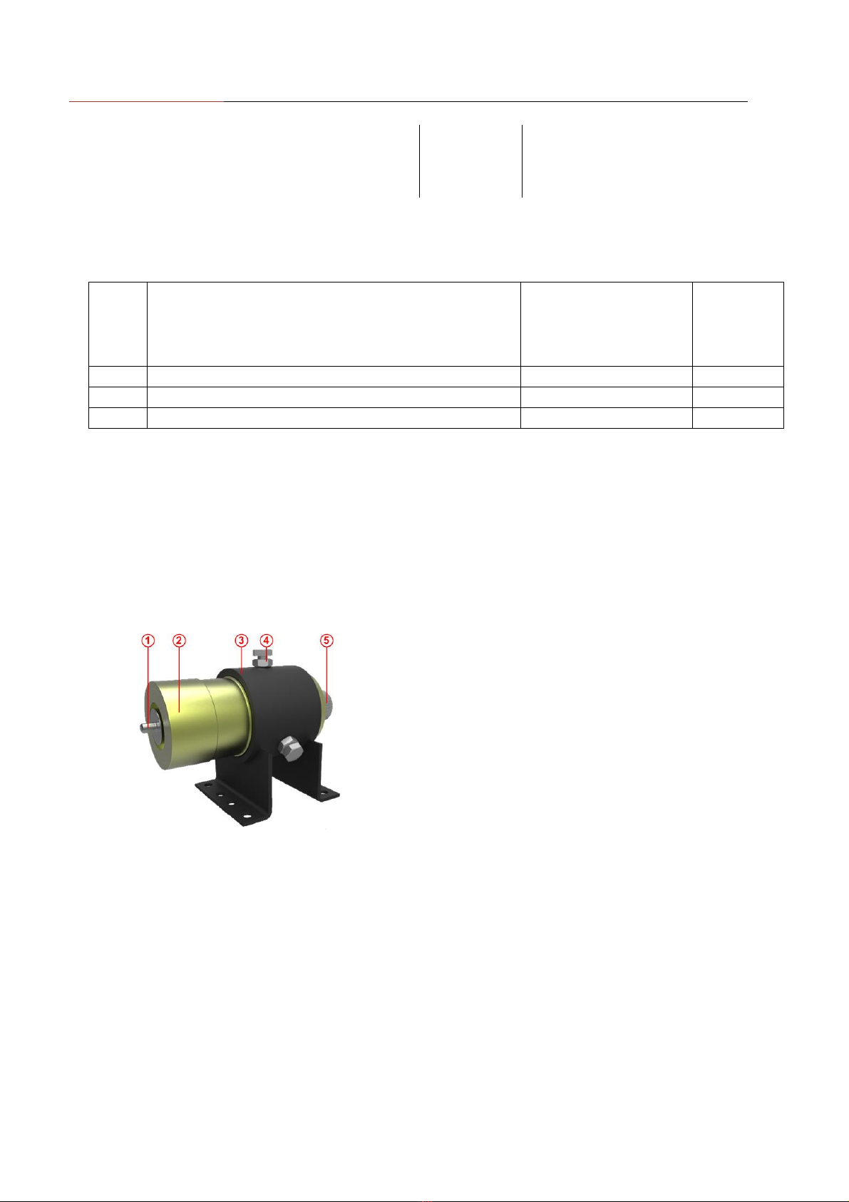
1.1.3. Content DPS-140(А,E)................................................................................................................... 6
Figure 1 –DPS-140(А) .................................................................................................................................. 6
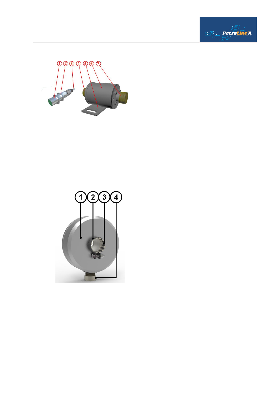
1.1.4. Content DPS-140(E)...................................................................................................................... 6
Figure 2 - DPS-140(I)..................................................................................................................................... 7
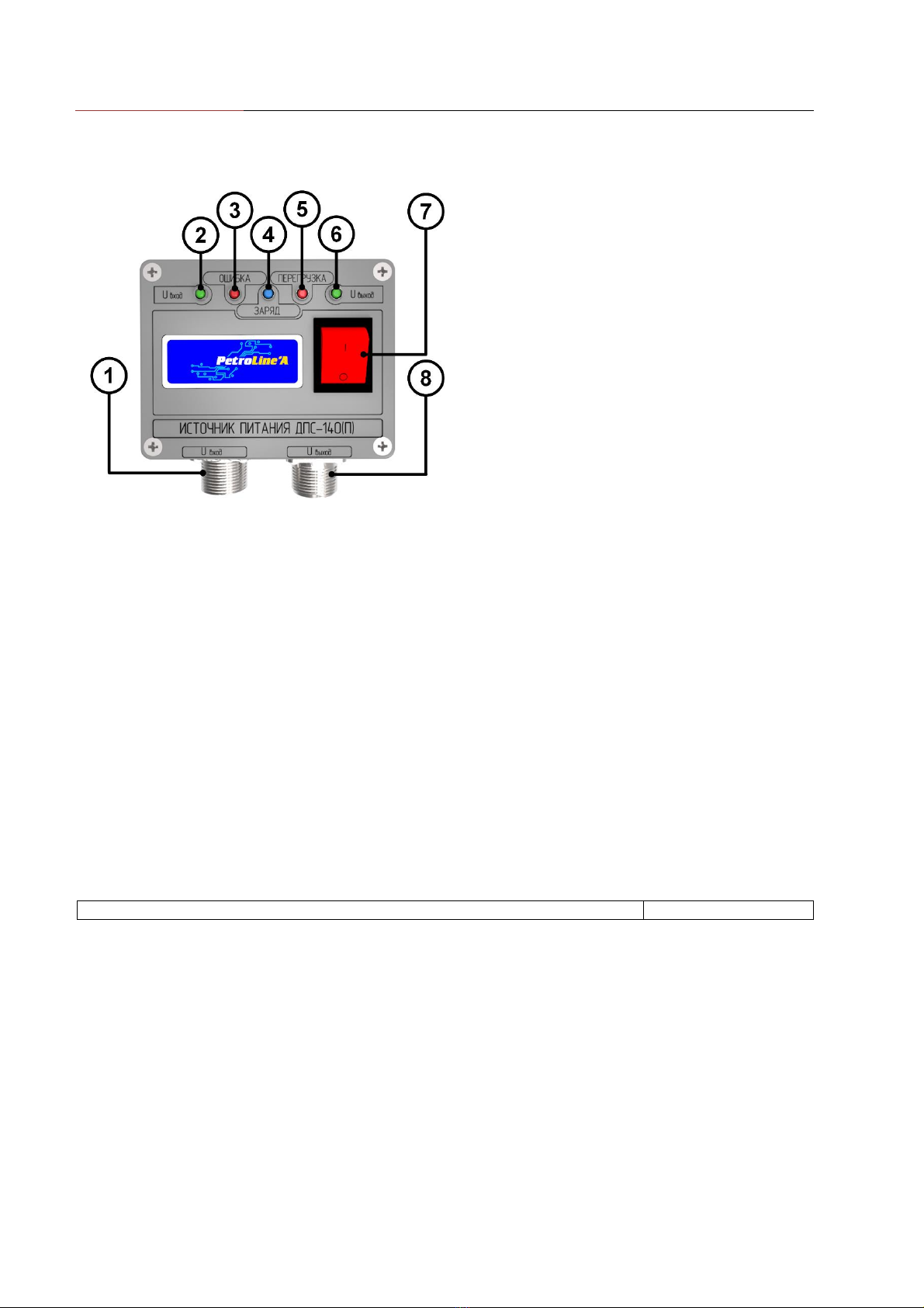
1.1.5. Content DPS-140(P)....................................................................................................................... 7
Figure 3. DPS-140(P)..................................................................................................................................... 7
Figure 4. Power Source for DPS-140(P)......................................................................................................... 8
1.1.6. Structure and operationing.............................................................................................................. 8
Table 5 –Ex marking..................................................................................................................................... 8
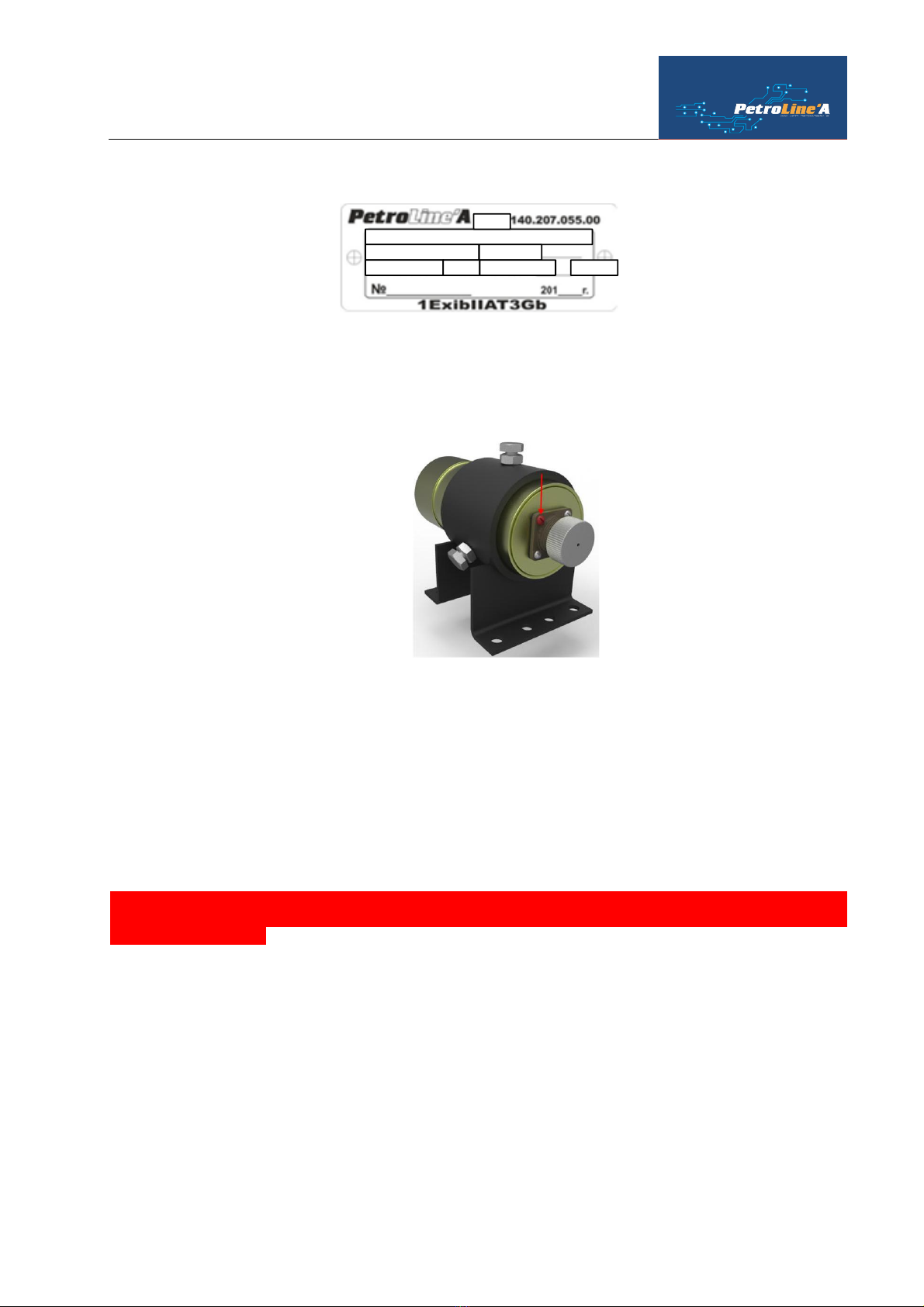
1.1.9. Marking and sealing....................................................................................................................... 8
Figure 5. Marking examples. .......................................................................................................................... 9
Figure 6. Sealing examples............................................................................................................................. 9
1.1.10. Packaging ...................................................................................................................................... 9
2. Usage............................................................................................................................................................. 9
2.1. Operational constraints............................................................................................................................. 9
2.1.9. Ex rating in operating..................................................................................................................... 9
2.2. Preparation of DPS-140(А,E,I,P) usage ................................................................................................... 10
2.2.1. Volume and sequence of DPS-140 (А,E,I,P)................................................................................. 10
2.2.2. Readiness checking for usage ....................................................................................................... 10
2.2.3. Setting description after preparation for a work:............................................................................ 10
2.2.4. DPS-140(А,E,P) Orientation and indication.................................................................................. 10
Figure 8. DPS-140(А,E) Setting example (at shaft end drawworks)............................................................... 11
Figure 9. DPS-140(P) at drawworks shaft. .................................................................................................... 11
.................................................................................................................................................................... 11
Figure 10. Drawworks shaft-1200................................................................................................................. 12
2.2.5. DPS-140(I) Orientation ................................................................................................................ 12
Figure 11. DPS-140(I) Setting example (at drawworks drum)....................................................................... 12
2.2.6. DPS-140(А,E) Orientation (belt, chain drive)............................................................................... 12
2.2.7. DPS-140(А,E) Orientation (rod).................................................................................................. 12
2.2.9. DPS-140(I) Switch on guideness and parameter setting «TRIPPING RATE» in content of DEL-140.
13
2.2.10. DPS-140(А) Switch on quideness and parameter setting «TRIPPING RATE» in content of DEL-
150. 14
2.2.11. Guideness to parameter setting «TRAVELLING BLOCK POSITION» in content of DEL-150 .... 16
2.2.12. Setting guideness parameter «BIT DEPTH» in content of DEL-150 ............................................. 16
2.2.13. Setting guideness parameter «BIT POSITION» in content of DEL-150....................................... 17
2.2.14. DEL-150 Contractions regarding DPS-140(A) for parameters display on a control module screen. 18
Table 6 –Sensors abbreviations.................................................................................................................... 18

2019
OPERATION MANUAL
4
2.3. DPS-140 Usage........................................................................................................................................ 18
2.3.1. Sequence actions while DPS-140 usage........................................................................................ 18
Table 7 –Sensors adressess at RS-485 bus.................................................................................................... 18
2.3.3. DPS-140 Possible malfunctions while usage and recommendations for decoupling them ............... 18
Figure 12. Readings on a control module in operating mode.......................................................................... 19
Figure 13. Readings on a control module display when there is a disconnection with a sensor........................ 19
Figure 14. Readings on a display module window in operating mode ............................................................ 19
Figure 15. Readings on a display module window when there is a disconnection with a sensor ...................... 19
2.4. Acts in emergency situations ................................................................................................................... 19
2.4.1. Failures that can lead to accidents................................................................................................. 19
3.1. DPS-140 Maintenance....................................................................................................................... 19
3.1.1.General information............................................................................................................................. 19
3.1.2. Safety measures............................................................................................................................ 20
3.1.3. DPS-140 Maintenance procedure.................................................................................................. 20
3.1.4. DPS-140 Work Capacity Check.................................................................................................... 20
4. Current Maintenance................................................................................................................................. 20
4.1. DPS-140 Current Maintenance ................................................................................................................ 20
4.1.1 General information ..................................................................................................................... 20
5. Storage........................................................................................................................................................ 21
5.1. Storage conditions .................................................................................................................................. 21
6. Transportation ........................................................................................................................................... 21
6.1. Transportation requirements and conditions ........................................................................................... 21
7. Disposal....................................................................................................................................................... 21
Application 1. Certificate of compliance to ISO 9001:2015 ..................................................................................... 22
Application 2. Service centers ................................................................................................................................ 22

DPS-140
PLA 140.207.000.000RE
5
1. Description and work
1.1. DPS-140 Desription and work
1.1.1. DPS-140 Purpose
DPS-140 in a complex with DEL-140, DEL-150, DEL-150Еis designed to control of drawworks shaft rota-
tion of drilling and workover rigs.
DPS-140 is designed for operation of:
In Ex 1 zone with reference to Oil and Gas Safety Regulations Classification;
In open air, at climatic conditions of macroclimatic regions with moderate and cold weather in range
of -45 to +65 °С.
to control of drawworks shaft rotation of drilling and workover rigs.
1.1.2. DPS-140 Modifications and its technical characteristics:
Table 1 –Main technical characteristics and DPS-140(А,E) parameters
Pulse quantity per rpm
4096
pulse.
The lowest measuring limit
0,01
m
Operating temperature range
-45 … +65
0С
Storage temperature
-50 … +50
0С
Ex marking
1ExibIIAT3Gb
Rated Supply Voltage
12
V
Ingress protection, GOST 14254-96
IP 65
Weather resistance, GOST 15150-89
NF1
Cable length
1...100
m
Table 2 –Main technical characteristics and parameters DPS-140(I)
Pulse quantity per rpm
Depends on
marks quantity
pulse.
Operating temperature range
-45 … +65
0С
Storage temperature
-50 … +50
0С
Ex marking
1ExibIIAT3Gb
Rated Supply Voltage
12
V
Ingress protection, GOST 14254-96
IP 65
Weather resistance,GOST 15150-89
NF1
Cable length
1...100
m
Table 3-Main technical characteristics and parameters DPS-140(P)
Pulse quantity per rpm
144
pulse.
The lowest measuring limit
0,01
M
Operating temperature range
-45 … +65
0С
Storage temperature
-50 … +50
0С
Ex marking
1ExibIIAT3Gb
Rated Supply Voltage
12
V

2019
OPERATION MANUAL
6
Ingress protection, GOST 14254-96
IP 65
Weather resistance, GOST 15150-89
NF1
Cable length
1...100
м
Table 4–Dimensions, weight
№
positio
n
Device
Dimensions, mm
Weight, kg
1
DPS-140(А,E)
62133
1,3
2
ДПС-140(I)
62110
1,1
3
ДПС-140(P)
15052
1,2
1.1.3. Content DPS-140(А,E)
DPS-140(А,E) consists from built-in absolute encoder and electronic layout which include:
-filters;
-analogue-to-digit transducer;
-microprocessor;
-layout of power source stabilization;
-intrinsic block at power in .
Figure 1 –DPS-140(А)
1. Sensor shaft;
2. Sensor enclosure;
3. Fixer's enclosure;
4. Tension bolt;
5. Sensor socket cover.
1.1.4. Content DPS-140(E)
DPS-140(E) consists of КDD-140 Disrete Data Input Controoler with connectable pulse sensor.

DPS-140
PLA 140.207.000.000RE
7
Figure 2 - DPS-140(I)
1. Inductive wire-free
sensor (VBI);
2. VBI Retaining nuts;
3. Cable with VBI;
4. Socket cover for VBI sensor connection
5. KDD-140 bracket enclosure;
6. KDD-140 Enclosure;
7. Connector for communication cable tapping.
1.1.5. Content DPS-140(P)
DPS-140(P) (fig. 3) consists of enclosure with built-in measuring rim and electronic layout which includes:
-filters;
-analogue-to-digit transducer;
-microprocessor;
-layout of power source stabilization;
-intrinsic block at power in .
Figure 3. DPS-140(P)
1. DPS-140(P) Enclosure;
2. Clamp;
3. Axle;
4. Connector for communication cable tapping;
To maintain DPS-140(P) position in case of power loss additionally with customer's approval «power source»
for DPS-140 (P) is used (fig.4)

2019
OPERATION MANUAL
8
Figure 4. Power Source for DPS-140(P)
1. Socket for communication cable connection
to control module;
2. Power in voltage indicator;
3. Battery charge error indicator;*
4. Battery charge indicator;
5. Circuit Current Reload Indicator (more than
100мА)
6. Power out voltage indicator;
7. Switch on button;
8. Socket for communication cable connection
to DPS-140(P);
*Reasons: 1. Breakdown of accumulator battery. 2. High temperature of accumulator battery.
1.1.6. Structure and operationing
The measured value of the number of pulses per revolution and the position relative to the specified “zero” is
transmitted via RS-485 communication channel to MU-150 control module for recording data and transmitting them to
indicate on the screen of the display module.
1.1.7. Measuring instrumentation and tool
In the process of installation, start-up and operation no special measuring instruments are required.
For installation and maintenance of DPS-140 (A, E, I, P), standard tools of installation specialist are used.
1.1.8. Ensuring explosion safety of DPS-140 (A, E, P)
Intrinsic safety (Ex attribute) 1ExibIIAT3Gb DPS-140 (A, E) is provided by an intrinsically safe electrical
circuit (ib).
It can be used in hazardous areas of outdoor installations (Chapter 7.3 PUE) corresponds to zone 1, the group
of explosion-proof electrical installations IIA, temperature class T3 according to the Safety Regulations in the oil and
gas industry, approved by Rostechnadzor.
Table 5 –Ex marking
DPS-140(А,E),DPS-140(I), DPS-140P
1ExibIIAT3Gb
1.1.9. Marking and sealing
Markings on the enclosures of the components of DPS-140 (A, E, I, P) include the following data:
1. Trademark or name of the manufacturer;
2. Type of product;
3. Serial number and year of manufacture;
4. Marking of explosion protection;
5. Special sign of explosion safety;
6. The range of ambient temperatures during operation;
7. The name of the certification body and the number of the certificate of conformity.
Other data required by regulatory and technical documentation, which the manufacturer must reflect on the
label, may also be used.

DPS-140
PLA 140.207.000.000RE
9
Figure 5. Marking examples.
Position and Velocity Sensor DPS-140(P)
INGRESS PROTECTION ADDRESS
EXECUTION NF1 MEAS.LIMIT m/sec
PLA
The devices enclosures containing electronic circuits and electromechanical components are sealed to prevent
unauthorized access. The repair is made by the manufacturer or a specialized enterprise (application), which has been
delegated the authority to repair.
Figure 6. Sealing examples.
1.1.10. Packaging
To transport DPS-140(А,E,I,P) in DEL-140, DEL-150 complex, plywood boxes with metal knobs for carrying.
2. Usage
2.1. Operational constraints
2.1.9. Ex rating in operating
The operation of DPS-140 (A, E, I, P) is allowed to personnel who have studied this instruction, passed the
appropriate instructions and have the necessary tolerances to work in hazardous areas.
During the work it is necessary to be guided:
- “Rules on labor protection during operation of electrical installations”;
- the current rules of electrical installations;
- requirements of the operating manual DEL-150;
- requirements of this guide.
!!!WHILE OPERATION IT IS NECESSARY TO CONTROL DEVISE AND COMMUNICATION CABLES
STATE. IF THERE IS ANY MECHANIAL DAMAGE OF DPS-140I COMMUNICATION CHANNELS OPERA-
TION IS FORBIDDEN!
During operation, it is prohibited to break the seals and open DPS-140 (A, E, I, P).
When the control module is on, it is prohibited to connect and disconnect the connectors of the connecting
cables. In case of detection of malfunctions, it is necessary to turn off the device, disconnect the power cable from the
power source. Then replace the faulty device with a known, working, plugging in, according to the documentation
(“DEL-150, DEL-140 Operating Manual”). After replacement, check the reliability of the connections and grounding
of the module housings to the mass of the lift.
During operation, periodically check the status of communication cables. If a violation of the protective layer
on the cable lines is detected, immediately turn off the power supply and replace the damaged cable.
Prevent sealing failure. If faults are detected, switch off the power supply and replace the faulty device.
If mechanical damage is found, remove the faulty device and send it in for repair.

2019
OPERATION MANUAL
10
2.2. Preparation of DPS-140(А,E,I,P) usage
While operation it is necessary to be guided by p.2.2. «DEL -150 Operation Manual»
2.2.1. Volume and sequence of DPS-140 (А,E,I,P)
External examination includes checking:
- states of contacts, flexible connections and leads;
- availability of mounting bolts and nuts;
- ease of movement and no damage to the threads;
- the state of cable entries, their seals;
- tightness of the sensor mounting bolts;
- the integrity of the painting sensors.
2.2.2. Readiness checking for usage
- When connecting to a control module, check the integrity of the sensor control module and cable con-
nectors.
The cable from the sensor is connected to any of “RS-485”connectors.
Figure 7. Control module connectors (switch module) to connect DPS-140(А,E,I,P).
Level1 Level2 Sensor Sensor Sensor Sensor Indicator Commutator
ServiceIndicatorGas3Gas2Gas1Power
Alarm Blocking Digital sensors communication line
2.2.3. Setting description after preparation for a work:
-- After the first power up, edit the necessary parameters:
-o maximum values
-o coefficients;
-o reset the necessary parameters;
-- After replacing the sensors as necessary, edit the operating parameters;
-- The settings should be carried out according to the information set out in the “DEL-150 Settings
Guide”.
2.2.4. DPS-140(А,E,P) Orientation and indication
For DPS-140 there are several mounting options. The choice of option depends on the type of power supply,
the current conditions and the available space for the installation of the equipment. Mounting method on ana-logical
winches may vary.
For security purposes, DPS-140 should be mounted with the winch stopped.
- DPS-140 is installed in an accessible place for safe installation;
- The installation site can be a free end of the winch shaft or a pre-prepared platform near the winch;
- Transmission of rotation can be carried out by a chain, a belt or a cable (by prior agreement with the cus-
tomer).

DPS-140
PLA 140.207.000.000RE
11
Figure 8. DPS-140(А,E) Setting example (at shaft
end drawworks)
1. Flange, fixed at shaft end drawworks ;
2. Sensor enclosure;
3. Angle connector;
4. Tension wire to exclude rotation.
1. DPS-140(P);
2. Tension too exclude DPS-140(P) sensor enclosure rota-
tion;
3. Drawworks shaft*;
*Shaft is designed according to specified drawworks rig with a customer approval. Rig Drawworks-1200 example is
shown at figure 10
Figure 9. DPS-140(P) at drawworks
shaft.

2019
OPERATION MANUAL
12
Figure 10. Drawworks shaft-1200
Rig swivel adjusted shaft
DPS-140(P)
Position and
Velocity sensor
2.2.5. DPS-140(I) Orientation
For safety reasons, mount the sensor when the winch is stopped.
- DPS-140 (I) is installed in an accessible place for safe installation;
- A contactless inductive sensor from DPS-140 (I) is mounted on a bracket to adjust the gap between the
sensor surface and the rotating surface with the control lugs of the winch;
- Adjustable clearance should not exceed 5 mm.
Figure 11. DPS-140(I) Setting example (at drawworks drum)
2.2.6. DPS-140(А,E) Orientation (belt, chain drive)
- DPS-140 (A) is installed in an accessible place for safe installation;
- DPS-140 (A) is mounted on a platform or bracket to adjust the tension of a belt drive or chain (individ-
ual performance is possible).
2.2.7. DPS-140(А,E) Orientation (rod)
- DPS-140 (A) is installed in an accessible place for safe installation;
- DPS-140 (A) is mounted on the platform or bracket to adjust the cable tension (individual design is pos-
sible).
2.2.8. DPS-140(A,E,P) Orientation (at shaft end drawworks)
- DPS-140 (A, E, P) is installed at shaft end drawworks (method of fastening agreed with the customer in advance).
- DPS-140 (A, E, P) is fixed by a cable or an extension to prevent turning in a circle of its axis.
THE SENSOR MUST BE MOUNTED WITH FULL STOP DRAWWORKS ACCORDING TO
SAFETY REGULATIONS!

DPS-140
PLA 140.207.000.000RE
13
2.2.9. DPS-140(I) Switch on guideness and parameter setting «TRIPPING RATE» in content of DEL-140.
1. After the installation is completed, it is
necessary to turn on the control module
MU-140
2. After loading, on the front panel of the
control module in the main operating
mode, press the button with thenumber 1.
The display of the control module will
display
3.
Next, select group 2 by pressing the
number button 2. The display on the
control module displays
4. Calibrate the position and speed sensor (shaft drawworks revolution)
1. Enter the operating parameters view
mode by pressing the key combination
and .
2. Choose parameter (Р7 –setting of max
value speed TRIPPINGRATE)
3. Press for storage
4. Lift the hook in extreme position above
the table.
5. Further leaving on a line «Р7» press the
button combination + +
, enter the calibration mode.
At control module display the hook position at the lowest
point will be shown.
6. If the readings are different from 00.00,
zeros must be entered and fix by pressing
button
7. Press button one more time, then
move to the line «counter review at the
lowest point «0»».
–the lowest point «0»
The 7th LED in the
2d group refers to
DPS-140(I)

2019
OPERATION MANUAL
14
8. At any other reading enter 0000 and fix
by pressing button
- counter check at the lowest
point «0».
9. Enter the uppest value reading in sm
10. Then by pressing button one more
time, switch to the line «counter review at
the highest point»
- upper point (ex:10 meters)
11. Lift the hook at the necessaty height (10
м)
12. Pulse counter reading at the highest point
is fixed, by pressing button (At
this point, the calibration table is recorded
in the shaft drawworks revoultion
sensor.)
13. To exit to operation mode press
- counter check at the upper
point
The shaft drawworks revolution is completed at this stage.
2.2.10. DPS-140(А) Switch on quideness and parameter setting «TRIPPING RATE» in content of DEL-150.
1. After installation is completed, it is
necessary to turn on the MU-150
control module.
2. After loading, the indicator on the
front panel of the control module the
message corresponding to the param-
eters of the sensors found is dis-
played.
LOAD
TRIPPING RATE
3. To parameter set «TRIPPING
RATE» press + and
choose thenecessaryparameter in the
list
RPM
TRIPPING RATE
TB POSITION
BIT DEPTH
4. Set necessary max and min values.
5. Switch to calibration mode.
TRIPPING RATE,M/S
MAX
MIN
CALIBRATION

DPS-140
PLA 140.207.000.000RE
15
TRIPPING RATE,M/S
----------CALIBRATION-------
RESET
SET UPPER POINT
6. Lift the hook in extreme position.
7. Switch to mode «ZERO SET»
8. Follow the instructions shown at con-
trol module display.
TRIPPING RATE,M/S
RESET
LIFT A HOOK
PRESS ENTER
TRIPPING RATE,M/S
RESET
SET ZERO
Zero is set.
9. Lift the hook in extreme postion.
10. Switch to mode «Fix the highest
point».
TRIPPING RATE,M/S
----------CALIBRATION-------
RESET
SET UPPER POINT
11. Save the counter readings.
12. Set the necessary height value.
TRIPPING RATE,M/S
SET UPPER POINT
LIFT A CROWN
COUNTER: 000000000
TRIPPING RATE,M/S
SET UPPER POINT
LIFT A CROWN
HEIGHT,M: 00.00

2019
OPERATION MANUAL
16
TRIPPING RATE,M/S
SET UPPER POINT
COMPLETED
The set of the highest point is completed
«TRIPPING RATE» parameter set for DPS-140(А,P) is completed.
To exit to operating mode press
2.2.11. Guideness to parameter setting «TRAVELLING BLOCK POSITION» in content of DEL-150
1. After loading, the inscription corre-
sponding to the parameters of the
found sensors is displayed on the in-
dicator on the front panel of the con-
trol module.
LOAD
TB POSITION
TRIPPING RATE
2. To parameter setting
«TRAVELLING BLOCK
POSITION» press +
and choose the necessary parameter
in the list
RPM
TRIPPING RATE
TB POSITION
BIT DEPTH
3. Set necessary max values (position
above the table in meters)
4. Reset at the lowest point.
RPM
TRIPPING RATE
TB POSITION
BIT DEPTH
TB POSITION,M
MAX
RESET
BIAS
«TRAVELLING BLOCK POSITION» parameter setting for DPS-140(А,P) is completed.
*Option «offset» is aimed to coil tubing devices
2.2.12. Setting guideness parameter «BIT DEPTH» in content of DEL-150
After loading, the inscription corre-
sponding to the parameters of the
found sensors is displayed on the in-
dicator on the front panel of the con-
trol module.
LOAD
TB POSITION
TRIPPING RATE
1. To set «BIT DEPTH» press
+ and choose the
necessary parameter in the list
RPM
TRIPPING RATE
TB POSITION
BIT DEPTH

DPS-140
PLA 140.207.000.000RE
17
2. Switch on the depth mode.
3. Counting is done automatically,
according to the settings entered.
BIT DEPTH,M
MODE OFF
DEPTH 0000.0
PRESSURE LIM,AT 16.0
W.FILTER N 17
INSTR.LIM 1, Ts 02.0
INSTR.LIM 2, Ts 07.0
LIM RATE,M/s 0.13
«BIT DEPTH» parameter setting for DPS-140(А,P) is completed.
*Counting is possible if there is DN-130, TP-140D Pressure Transducer and DPS-140(А,P).
Notes on main parameters of «BIT DEPTH»:
-Value LIMITPRESSURE —value(pressure) of automatic enter to «Drill mode»;
-Value W.FILTER N —filtration value parameter «Bit load»;
-Value INSTR.LIMIT1,Ts —the lowest limit value «Bit load» from which the counting of depth in
case of the column weight is less than 10 Ts;
-Value ИНСТР.ПОРОГ2,Тс —the lowest limit value «Bit load» from which the counting of depth in
case of the column weight is more than 10 Ts;
-Value SPEED LIMIT,М/s —upper parameter value «Tripping rate» up to which the depth counting
is made.
-To manual counting «bit depth» it is necessary to have the parameter «HOOK LOAD
-To automatic count «bit depth» it is necessary to have the parameter «HOOK LOAD»«INLET MUD
FLOW PRESSURE»
It depends on the right parameter calibration «TRIPPING RATE».
2.2.13. Setting guideness parameter «BIT POSITION» in content of DEL-150
TB POSITION,M
MODE OFF
LOAD LIM,Ts 0.70
DEPTH 0000.0
Notes on main parameters of «BIT POSITION»:
Value LIMIT LOAD —the lowest value parameter (HOOK LOAD) for automatic control «BIT POSITION»;
Value DEPTH —parameter correction line «BIT POSITION»
It depends on the right parameter calibration «TRIPPING RATE».

2019
OPERATION MANUAL
18
2.2.14. DEL-150 Contractions regarding DPS-140(A) for parameters display on a control module screen.
Table 6 –Sensors abbreviations.
PARAMETER
CONTRACTION
SENSOR
ALTERNATIVES
Tripping rate
Tripping rate
DPS-140(А)
DPS-140(I), DPS-
140(P)
Travelling block postion above rotor table
TBP
DPS-140(А)
DPS-140(P)
Bit depth
Depth
DPS-140(А),
DN-130,
TP-140Д
DPS-140(P),
DN-130,
TP-140D
Penetration Rate
PenetrRate
DPS-140(А)
DPS-140(P)
Bit position
BitPos
DPS-140(А)
DPS-140(P)
The list can be updated.
2.3. DPS-140 Usage
2.3.1. Sequence actions while DPS-140 usage
-- Turn on the device;
-- Check the list of connected devices;
-- Sensors verification;
-- Editing the required parameters.
2.3.2. A view of connected devices list on the control module display MU-150
You can view a list of connected devices. The list displays the contracted names of devices (sensors, interlock
boards, indicators) and the address on the RS-485 bus (Table 7).
Main menu
1. Swith to the line
connected devices.
2. Press
REFERENCE PARAMETERS
OPERATING PARAMETERS
FILE COPY
CONNECTED DEVICES
SYSTEM STATUS
PARAMETER SETTINGS
SERVICE
Connected devices
3. Press
SENSORS
INDICATORS
BLOCKINGS
Sensors
A view of all con-
nected devices
DN-130
DPS-140 (A/E)
TP-140D(IN)
Table 7 –Sensors adressess at RS-485 bus.
№
Connected devices
Inscription at dis-
play MU-150
dec
1
Position and Velocity sensor (indicator)
DPS-140(I)
005
2
Position and Velocity sensor (indicator)
DPS-140(А/E)
006
3
Position and Velocity sensor (indicator)
DPS-140(P)
006
The table shows a list of existing devices. In the future, this list may be updated due to the appearance of new positions.
2.3.3. DPS-140 Possible malfunctions while usage and recommendations for decoupling them
The malfunction DPS-140 in DEL-150 can be judged by:

DPS-140
PLA 140.207.000.000RE
19
- according to indications on the display of the control module;
- according to indications in the corresponding window of the display module.
Figure 12. Readings on a control module in operating mode
LOAD
TB POSITION
TRIPPING RATE
Figure 13. Readings on a control module display when there is a disconnection with a sensor
LOAD
TB POSITION
TRIPPING RATE
Figure 14. Readings on a display module window in operating mode
TB POSITION,M
Figure 15. Readings on a display module window when there is a disconnection with a sensor
TB POSITION,M
When communication is lost, you must perform the actions in the following order:
- check the integrity of the communication cable;
- reconnect the cable to the free connector of the control module labeled "RS-485";
- check the presence of the parameter in the list of the control module;
- replace the cable;
- check the presence of the parameter in the list of the control module;
- replace the sensor;
- check the presence of the parameter in the list of the control module.
2.4. Acts in emergency situations
2.4.1. Failures that can lead to accidents
In case of failures that can lead to emergency situations, it is necessary to replace the failed device.
In all cases not described in this manual, follow the Federal norms and rules in the field of industrial safety
"Safety rules in the oil and gas industry".
3. Maintenance
3.1. DPS-140 Maintenance
3.1.1.General information
Maintenance is divided into:
- daily maintenance;
- periodic maintenance performed after working off a certain time, and after the move (before installation).
Operational and routine maintenance of DPS-140 is performed by personnel whose responsibilities include
ensuring the operability of the complex. The list of these works includes:

2019
OPERATION MANUAL
20
- check the status and control of the instrument;
- checking and monitoring the parameters of the DPS-140;
- operational actions for the replacement of damaged components with the registration of acts;
- check the inclusion of blocking signals;
- registration in the form according to the forms recommended by the manufacturer of all recorded deviations,
failures, work performed and other information.
3.1.2. Safety measures
When operating the complex, it is necessary to be guided by:
• chapter 3.4 «Electrical installations in hazardous areas» PEEP;
• current regulations for electrical installations;
• this operational documentation (ED) and other regulatory documents operating at the enterprise.
During operation, it is prohibited to open all devices that are part of the electronic dynamometer the DEL-150.
Works should be done upon requirement, but at least once a month:
3.1.3. DPS-140 Maintenance procedure
Maintenance is carried out in the following order:
1. Decontamination of the sensor and indicator enclosures;
2. Checking the safety of seals;
3. Decontamination the glass surfaces of the indicators;
4. Check availability and durability of fasteners;
5. Decontamination of connectors and contact groups;
6. Check for visible mechanical damage;
7. Replacement and (or) repair of damaged cable products;
8. Replacing of damaged sensors, indicators, other devices and components.
Wash the contacts of the connectors with an alcohol-gasoline mixture (need 3 ml) with a soft brush.
The absence of marks on carrying out maintenance in the Form (section "Accounting for technical
services") ATTRACTS A VIOLATION OF THE OPERATING RULES, and the manufacturer has
the right to withdraw the warranty.
3.1.4. DPS-140 Work Capacity Check
-Switch on the device;
-Check the list of connected devices;
-Check, edit operating parameters;
-Check blocking and alarm operationinig
-Check reflection of the relevant parameters on the Display Module.
4. Current Maintenance
4.1. DPS-140 Current Maintenance
4.1.1 General information
Repair is done on manufacturer plant or at specialized enterprise.
This manual suits for next models
1
Table of contents
Other Petroline-A Accessories manuals