A&D AD4329A-DLC User manual

AD4329A-DLC
Weighing Indicator
INSTRUCTION MANUAL
1WMPD4003952

AD4329A-DLC Page 2
Contents
1. Introduction .................................................................................................................................................... 4
1.1. Safety precautions .................................................................................................................................. 5
2. Part Names.................................................................................................................................................... 6
2.1. Front panel .............................................................................................................................................. 6
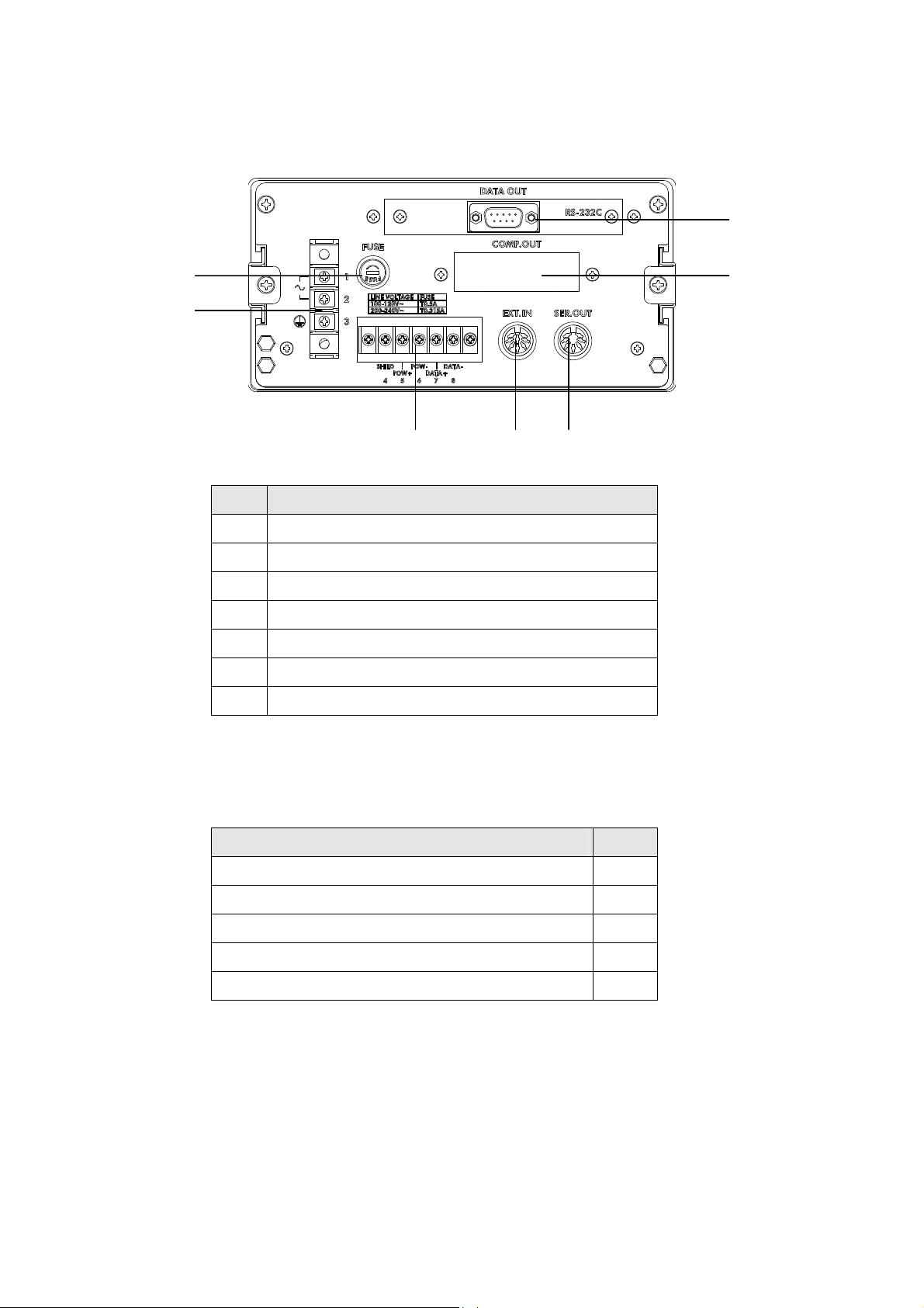
2.2. Rear panel............................................................................................................................................... 7
2.3. Accessories............................................................................................................................................. 7
3. Connecting to Power Supply ......................................................................................................................... 8
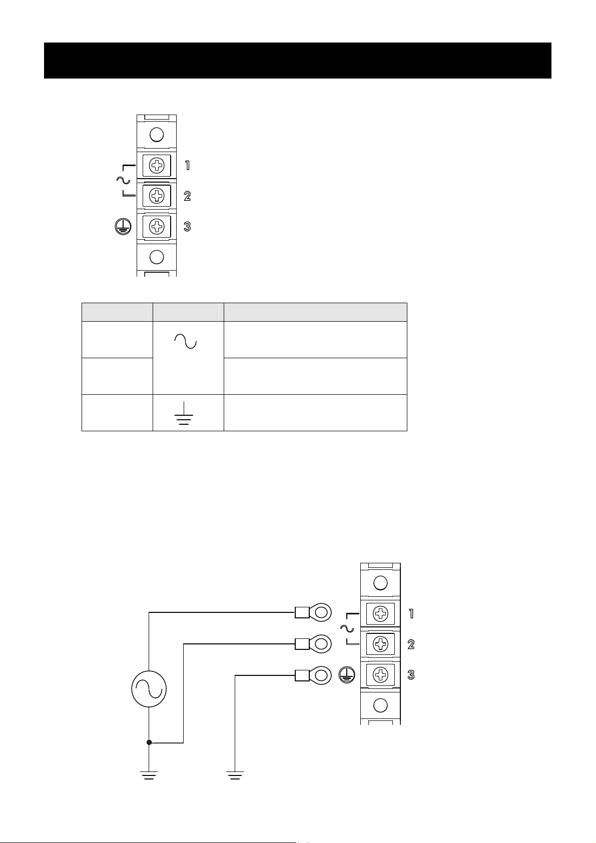
3.1. AC power supply input terminal assignment........................................................................................... 8
3.2. Connection Diagram ............................................................................................................................... 8
4. Connecting to Digital Load cells .................................................................................................................... 9
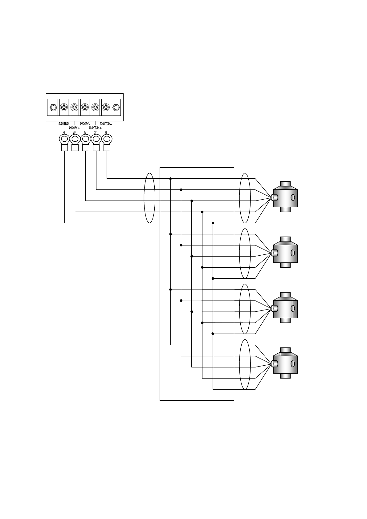
4.1. Load cell input terminal assignment ....................................................................................................... 9
4.2. Connection diagram.............................................................................................................................. 10
4.3. When connecting more than 6 load cells.............................................................................................. 11
5. Digital Load Cell Presetting ......................................................................................................................... 12
5.1. Setting the number of digital load cells connected ............................................................................... 12
5.2. Serial number settings of digital load cells............................................................................................ 13
6. Calibration.................................................................................................................................................... 15
6.1. Scale interval setting............................................................................................................................. 17
6.2. Maximum capacity setting..................................................................................................................... 17
6.3. Zero compensation at four corner adjustment ...................................................................................... 18
6.4. Adjustment weight at four corner adjustment ....................................................................................... 18
6.5. Four corner adjustment ...................................................................................................................... 19
6.6. Zero calibration ..................................................................................................................................... 20
6.7. Span calibration .................................................................................................................................... 20
6.8. Multi-interval function ............................................................................................................................ 21
6.9. Scale interval and capacity settings for each range ............................................................................. 22
6.10. Linearity calibration ............................................................................................................................. 23
6.11. Gravitational acceleration compensation............................................................................................ 25
6.12. Error display ........................................................................................................................................ 26
7. Basic Weighing Function ............................................................................................................................. 27
7.1. Weighing mode ..................................................................................................................................... 27
7.2. Display OFF (Standby mode) ............................................................................................................... 28
7.3. Net / Gross value selection ................................................................................................................... 28
7.4. Push zero .............................................................................................................................................. 28
7.5. Zero tracking ......................................................................................................................................... 28
7.6. Power-on zero....................................................................................................................................... 28
7.7. Zero detection ....................................................................................................................................... 28
7.8. Stability detection.................................................................................................................................. 28
7.9. Tare....................................................................................................................................................... 29
7.10. Preset tare........................................................................................................................................... 29
7.11. Accumulation....................................................................................................................................... 30
7.12. High Resolution................................................................................................................................... 31

AD4329A-DLC Page 3
8. External Control Input.................................................................................................................................. 32
9. Standard Serial (Current Loop) Output........................................................................................................ 33
9.1. Output data format ................................................................................................................................ 35
10. Comparator Output (Option-02)................................................................................................................. 36
11. RS-232C Interface..................................................................................................................................... 39
11.1. Output data format .............................................................................................................................. 41
11.2. Command format ................................................................................................................................ 42
12. Confirming and Initializing the Operations and Setting Values............................................................................. 43
12.1. Confirming the digital load cell............................................................................................................ 44
12.2. Confirming the keys ............................................................................................................................ 45
12.3. Confirming the external control input .................................................................................................. 46
12.4. Confirming the standard serial output................................................................................................. 46
12.5. Confirming the comparator outputs..................................................................................................... 47
12.6. Confirming RS-232C........................................................................................................................... 47
12.7. Confirming the F function setting values............................................................................................. 48
12.8. Confirming the CF function setting values .......................................................................................... 48
12.9. Confirming the calibration setting values ............................................................................................ 49
12.9.1. Confirming the scale interval (resolution)..................................................................................... 50
12.9.2. Confirming the multi-interval settings ........................................................................................... 50
12.9.3. Confirming the linearity calibration ............................................................................................... 50
12.9.4. Confirming the gravitational acceleration compensation 1 .......................................................... 50
12.9.5. Confirming the gravitational acceleration compensation 2 .......................................................... 51
12.9.6. Confirming the weight value at span calibration........................................................................... 51
12.9.7. Confirming the load cell output at zero calibration ....................................................................... 51
12.9.8. Confirming the maximum capacity ............................................................................................... 51
12.9.9. Confirming the weight value at four corner adjustments.............................................................. 52
12.9.10. Zero compensation value for four corner adjustments............................................................... 52
12.9.11. Compensation value for four corner adjustments ...................................................................... 52
12.10. Initializing .......................................................................................................................................... 53
13. Function Setting......................................................................................................................................... 54
13.1. F-function setting method ................................................................................................................... 54
13.2. F-function list....................................................................................................................................... 55
13.2.1. Basic weighing function................................................................................................................ 55
13.2.2. External control input.................................................................................................................... 56
13.2.3. Comparator output ....................................................................................................................... 57
13.2.4. Standard serial output .................................................................................................................. 57
13.2.5. RS-232C interface........................................................................................................................ 58
13.3. CF-function setting method................................................................................................................. 59
13.4. CF-function list .................................................................................................................................... 60
14. Check the Software Version ...................................................................................................................... 62
15. Specifications............................................................................................................................................. 63

AD4329A-DLC Page 4
1. Introduction
AD4329A-DLC is a digital load cell weighing indicator that enables use of truck scales.
By combining the AD4329A-DLC with an A&D digital load cells (LCCD20 series), a weighing system with higher
lightning resistance performance can be built, and electronic corner adjustment can be performed easily and
precisely. Up to eight digital load cells can be connected in parallel.
AD4329-DLC's interface has standard serial output to enable connection to A&D printers and displays and RS-
232C to enable connection to PCs. In addition, comparator relay output can be provided as an option.

AD4329A-DLC Page 5
1.1. Safety precautions
For safe and correct usage, read the following precautions carefully before using the indicator.
Precautions on design
WARNING
●Provide an external safety circuit to the indicator so that the safety of the whole system can be
secured even if errors occur in the external power supply or in the indicator.
Precautions on installation
WARNING
●Do not use the indicator in the following environments:
- Where the temperature and the humidity exceed the specifications
- Where corrosive gases or flammable gases are present
- Where the indicator gets wet with oil, chemicals or water
Please note that securing the indicator to the control panel will provide the indicator outside of the
control panel with IP65 protection.
●When installing or removing the indicator, be sure to turn off all the external power supplies used
beforehand.
Precautions on wiring
WARNING
●When wiring the indicator, be sure to turn off all the external power supplies used beforehand.
●When wiring is complete, be sure to attach the terminal block cover provided with the indicator.
●Be sure to ground the indicator.
CAUTION
●Do not clamp control wires or communication cables with power lines, and do not place them close to
power lines.
●Place the load cell cable sufficiently away from high frequency circuits such as high voltage power
lines and inverter load circuits.

AD4329A-DLC Page 6
2. Part Names
2.1. Front panel
No. Name Description
1 Numerical display Displays weight value or setting value.
2 Unit display The set unit illuminates.
M+ Illuminates when the total value is stored.
MD Illuminates when the weight value is stable.
GROSS Illuminates when the gross value is displayed.
NET Illuminates when the net value is displayed.
PT Illuminates when the preset tare value is displayed.
3 Status mark
display
ZERO Illuminates when the weight value is within 1/4 of the minimum division.
4 Key switch with
sealing cover CAL key Switches to calibration mode.
OPR/STB key Turns the display on/off.
Preset tare key Displays the preset tare value.
M+ key Adds the current value to the stored total value.
Mode key Used for the accumulation function, calibration, unit selection, etc.
Net/Gross key Switches between net/gross data display.
+/- key Selects the sign when setting the value.
Zero key Zeros the current display.
key Selects the place of the digit when setting the value.
Tare key Performs tare.
key Specifies the value for the selected digit when setting a value.
Print key Outputs data.
5 Key switches
key Finalizes data entry and saves the set value.
12
3
4 5
kg

AD4329A-DLC Page 7
2.2. Rear panel
No. Name
1 AC power input terminal
2 Digital load cell input terminal
3 Fuse holder
4 External control input connector
5 Standard serial output connector
6 RS-232C I/F connector
7 Option 02 (comparator output) slot
2.3. Accessories
Name Qty.
Instruction Manual 1
Connector for external control input 1
Connector for standard serial output 1
Spare fuse 1
Rubber foot 4
1
2 4 5
3
6
7

AD4329A-DLC Page 8
3. Connecting to Power Supply
3.1. AC power supply input terminal assignment
Use an M4 solderless terminal with a width of 8.6 mm or less
Terminal No. Symbol Description
1 AC power input (Live)
Unearthed conductive part
2
AC power input (Neutral)
Earthed conductive part
3
Ground terminal
The test below is performed for lightning resistance performance of the AD4329A-DLC.
Impulse withstand voltage test (in the air)
JEC-0202 conformity to impulse voltage and current test
Standard lightning impulse voltage 1000kV
3.2. Connection Diagram
N:Neutral
L:Live

AD4329A-DLC Page 9
4. Connecting to Digital Load cells
4.1. Load cell input terminal assignment
Use an M3 solderless terminal with a width of 6.2 mm or less.
Terminal No. Symbol Description
4 SHILD Shield
5 POW+ Load cell excitation voltage +
6 POW- Load cell excitation voltage -
7 DATA+ Load cell data +
8 DATA- Load cell data -

AD4329A-DLC Page 10
4.2. Connection diagram
When you connect the digital load cells in parallel, use a junction box for digital load cells. Connecting the
weighing indicator to four digital load cells is as shown below. Recommended cable is AX-KO3217 (A&D).
Data -
Data +
Power -
Power +
Shield
Junction Box AD4388-4

AD4329A-DLC Page 11
4.3.
When connecting more than 6 load cells
When connecting more than six load cells, multiple junction boxes are required.
In that case, to have a termination resistance of 100 , do the following.
Leave the jumper (JP1) in the junction box installed furthest from the weighing indicator as is and cut the
jumpers (JP1) in the other junction boxes, using wire cutters.
Fig.4 shown below is an example connection diagram when using an AD4388-4 and an AD4388-6 to connect
eight digital load cells.
R
W
GBY
100
C1
R1
JP1
100
C1
R1
JP1
R
W
G
B
Y
To weighing indicator
No connection
Cut the jumper (JP1).
AD4388-6
AD4388-4
R
W
GBY
R
W
GBY
R
W
GBY
R
W
GBY R
W
GBY
R
W
GBY R
W
GBY
R
W
G
B
Y
R
W
GBY R
W
GBY

AD4329A-DLC Page 12
5. Digital Load Cell Presetting
Before operation, set the number of load cells and serial number.
Before setting, "errlC 1" will appear in the display.
5.1. Setting the number of digital load cells connected
Press [OPR/STB] in weighing mode to go to Standby mode (" . ").
While pressing and holding [MODE], press [OPR/STB] to go to F-function mode (f-01).
Press [CAL] to go to CF-function mode.
Select "Cf-100" by the following key operations.
[ZERO]: Move the flashing digit.
[TARE]: Change the value of the flashing digit.
[PRINT]: Confirm the displayed item.
Change the number of digital load cells connected by the following key operations.
[TARE]: Change the value of the flashing digit.
[PRINT]: Update to the new value and return to the item selection.
[MODE]: Cancel the value setting and return to the item selection.
Cf-00"0
Cf-"100
"1
"4
Cf-10"1
Update Cancel
Enter
Change
Change Move

AD4329A-DLC Page 13
5.2. Serial number settings of digital load cells
Before operation, check the serial number on the digital load cell. And set the serial number specified for each
digital load cell to the AD4329A-DLC.
When your weighing scale is built using four digital load cells, the serial numbers for four units must be set.
When setting the serial number, set it in the order for corner adjustment starting from "Cf-101".
Check the serial number marked on each digital load cell.
For example, with the LCCD20 series (manufactured by A&D), it is marked on the rating label on the body.
The last seven of the nine digits of serial number "SER." are the serial number to be set.
Set "2900414"
to CF-101 for 1st load cell.
Set "2900415"
to CF-102 for 2nd load cell.
Set "2900417"
to CF-104 for 4st load cell.
Set "2900416"
to CF-103 for 3rd load cell.
00414
29
00415
29
00416
29
00417
29

AD4329A-DLC Page 14
Select "Cf-101" by the following key operations in CF-function mode.
[ZERO]: Move the flashing digit.
[TARE]: Change the value of the flashing digit.
[PRINT]: Confirm the displayed item.
Change the setting value by the following key operations.
[ZERO]: Move the flashing digit.
[TARE]: Change the value of the flashing digit.
[PRINT]: Update to the new value and return to the item selection.
[MODE]: Cancel the value setting and return to the item selection.
Set the serial numbers for all of the digital load cells connected by using the
same procedure.
Update Cancel
Change Move
Confirm
Change
Cf-00"0
Cf-10"1
"0000000
290041"4
Cf-10"2
Move
Confirm

AD4329A-DLC Page 15
6. Calibration
Calibrate the AD4329A-DLC so that it can properly convert the signal from the load cell to a mass value.
Set or execute the following items required for calibration.
・ Scale interval (resolution) setting
・ Maximum capacity setting
・ Four corner adjustment
・ Zero calibration
・ Span calibration
・ Linearity calibration (if necessary)
・ Gravity acceleration compensation (if necessary)
Refer to "13.3 CF-function setting method” regarding setting of decimal point position (CF-000) and units (CF-001).

AD4329A-DLC Page 16
Select the item by the following key operations.
0.0
Cal in
Scale interval
setting
d-01
C "10000
Cal 0
f "10000
Maximum
capacity setting
Zero calibration
Span calibration
4C Cal0
g1 "9798
Cap2-02
lnr 1
Linearity calibration
Multi-interval function
Gravitational acceleration
compensation
Four corner adjustment
end
CanCel
.
Save
After 2 seconds
Cancel

AD4329A-DLC Page 17
6.1. Scale interval setting
Select a scale interval from 1d, 2d, 5d, 10d, 20d, or 50d by the following
key operations.
[TARE]: Select the scale interval.
[PRINT]: Confirm the changed value and go to the next item.
[MODE]: Skip this item and go to the next item.
6.2. Maximum capacity setting
Set a maximum capacity by the following key operations
[TARE]: Change the value of the flashing digit.
[ZERO]: Move the flashing digit.
[PRINT]: Confirm the changed value and go to the next item.
[MODE]: Skip this item and go to the next item.
d-01
d-10
C "10000
C 1"2000
Confirm
Change
Move
Next page
Confirm
Change
Skip
Skip

AD4329A-DLC Page 18
6.3. Zero compensation at four corner adjustment
Press [PRESET TARE].
Press [PRINT].
Empty the scale. When the MD mark illuminates, press [PRINT] to
execute zero compensation at four corner adjustment and go to the next
item.
6.4. Adjustment weight at four corner adjustment
Press [PRINT].
Set an adjustment weight value for corner adjustment by the following
key operations.
[TARE]: Change the value of the flashing digit.
[ZERO]: Move the flashing digit.
[PRINT]: Update to the new value and go to the next item.
4C adj
10000
"1000
Change Move
Next page
Update
Cal 0
4C Cal0
9507.0
Execute
Previous page

AD4329A-DLC Page 19
6.5. Four corner adjustment
The example shown in the figure is when the weighing scale is built using four digital
load cells.
Press [PRINT].
Put the adjustment weight on the 1st digital load cell.
When the MD mark illuminates, press [PRINT] to execute corner
adjustment for 1st digital load cell.
Press [PRINT].
Put the adjustment weight on the 2nd digital load cell.
When the MD mark illuminates, press [PRINT] to execute corner
adjustment for 2st digital load cell.
Execute corner adjustment for all of the load cells connected
by using the same procedure.
After that, the display proceeds as shown in the example at
the right.
lC1adj
lC2adj
4C end
Previous page
1000.0
lC3adj
1000.0
Execute
Execute
For 2 seconds
Next page
Cal 0

AD4329A-DLC Page 20
6.6. Zero calibration
Empty the scale. When the MD mark illuminates,press [PRINT] to
execute zero calibration and go to the next item.
If [MODE] is pressed, the zero calibration will be skipped.
6.7. Span calibration
"CAL F" will appear in the display for 2 seconds.
Set the calibration weight by the following key operations.
[TARE]: Change the value of the flashing digit.
[ZERO]: Move the flashing digit.
[MODE]: Skip span calibration, and return to scale interval
setting.
Place the calibration weight on the scale.
When the MD mark illuminates,press [PRINT] to execute span
calibration.
If the calibration was done successfully, "CAL End" is displayed.
Pressing [CAL] finishes the calibration and "End" is displayed.
Pressing [MODE] returns to scale interval setting again.
Pressing [OPR/STB] twice goes to weighing mode.
d-01
Cal 0
Execute
Cal f
f "10000
Change Move
f 1"2000
Cal end
Previous page
Execute
Skip
After 2seconds
Skip
end
0.00
Table of contents
Other A&D Accessories manuals
Popular Accessories manuals by other brands

Neo Electronic
Neo Electronic NAS-WS01Z installation instructions

Emerson
Emerson Net Safety Millennium II SC310 manual

Honeywell
Honeywell DT8012F4 installation instructions

Honeywell
Honeywell TC840ME Installation and maintenance instructions

Califone
Califone LP4 user manual

Grizzly
Grizzly H7585 instruction sheet