HYTROL ProSort 400 Manual

Installation
and
Maintenance
Manual
with Safety Information
and Parts List
RECOMMENDED SPARE PARTS HIGHLIGHTED IN GRAY
IMPORTANT!
DO NOT DESTROY
Model ProSort 400
HYTROL CONVEYOR CO., INC.
© COPYRIGHT 2005–HYTROL CONVEYOR CO., INC.
Jonesboro, Arkansas
Effective October 2005
Bulletin # 562
¡IMPORTANTE!
NO DESTRUIR
Manual
de Instalación
y
Mantenimiento
con Información sobre Seguridad
y Lista de Partes
LAS PARTES DE REPUESTO RECOMENDADAS SE RESALTAN EN GRIS

2
●Table of Contents ●Tabla de Contenido
Warning Signs . . . . . . . . . . . . . . . . . . . . . . . . .3
INTRODUCTION
Receiving and Uncrating . . . . . . . . . . . . . . . . .4
INSTALLATION
Installation Safety Precautions . . . . . . . . . . . .5
Location . . . . . . . . . . . . . . . . . . . . . . . . . . . . .6
Conveyor Set-Up . . . . . . . . . . . . . . . . . . . . . .7
Electrical Equipment . . . . . . . . . . . . . . . . . . .10
OPERATION
Operation Safety Precautions . . . . . . . . . . .12
Conveyor Start-Up . . . . . . . . . . . . . . . . . . . .12
MAINTENANCE
Maintenance Safety Precautions . . . . . . . . . .13
Lubrication . . . . . . . . . . . . . . . . . . . . . . . . . .13
Controlling the ProSort . . . . . . . . . . . . . . . .14
Divert Switch Checklist . . . . . . . . . . . . . . . .20
Carrying Chain Installation . . . . . . . . . . . . .22
Locating the Spur . . . . . . . . . . . . . . . . . . . . .24
Divert Switch Removal Procedure . . . . . . .25
Trouble Shooting . . . . . . . . . . . . . . . . . . . . .26
Preventive Maintenance Checklist . . . . . . . .28
Preventive Maintenance Details . . . . . . . . . .30
How To Order Replacement Parts . . . . . . .31
ProSort 421Parts Drawing . . . . . . . . . . . . . .32
ProSort 421 Parts List . . . . . . . . . . . . . . . . .36
ProSort 431 Parts Drawing . . . . . . . . . . . . .38
ProSort 431 Parts List . . . . . . . . . . . . . . . . .42
Divert Switch Parts Drawing . . . . . . . . . . . .44
Divert Switch Parts List . . . . . . . . . . . . . . . .45
Safety Switch Assembly . . . . . . . . . . . . . . . .46
Señales de Advertencia . . . . . . . . . . . . . . . . . . . .3
INTRODUCCION
Recepción y Desembalaje . . . . . . . . . . . . . . . . . .4
INSTALACION
Medidas de Seguridad al Instalar . . . . . . . . . . . .5
Localización . . . . . . . . . . . . . . . . . . . . . . . . . . . .6
Montaje . . . . . . . . . . . . . . . . . . . . . . . . . . . . . . .7
Equipo Eléctrico . . . . . . . . . . . . . . . . . . . . . . . .10
OPERACION
Medidas de Seguridad . . . . . . . . . . . . . . . . . . .12
Arranque del Transportador . . . . . . . . . . . . . . .12
MANTENIMIENTO
Medidas de Seguridad . . . . . . . . . . . . . . . . . . .13
Lubricación . . . . . . . . . . . . . . . . . . . . . . . . . . . .13
Controlando el ProSort . . . . . . . . . . . . . . . . . . .14
Revisión del Interruptor . . . . . . . . . . . . . . . . . .20
Instalación de Cadenas . . . . . . . . . . . . . . . . . .22
Colocando las Espuelas . . . . . . . . . . . . . . . . . .24
Remoción del Interruptor Desviador . . . . . . . . .25
Resolviendo Problemas . . . . . . . . . . . . . . . . . . .27
Lista del Plan de Mantenimiento . . . . . . . . . . .29
Detalles de Mantemiento . . . . . . . . . . . . . . . . .30
Como Ordenar Partes de Repuesto . . . . . . . . .31
Dibujo de Partes del ProSort 421 . . . . . . . . . .32
Lista de Partes del ProSort 421 . . . . . . . . . . . .36
Dibujo de Partes del ProSort 431 . . . . . . . . . .38
Lista de Partes del ProSort 431 . . . . . . . . . . . .42
Dibujo del Interruptor Desviador . . . . . . . . . . .44
Partes del Interruptor Desviador . . . . . . . . . . .45
Interruptor de Seguridad . . . . . . . . . . . . . . . . .46

3
● Warning Signs ● Señales de Advertencia
In an effort to reduce the possibility of injury to personnel
working around HYTROL conveying equipment, warning signs are
placed at various points on the equipment to alert them of
potential dangers. Please check equipment and note all warning
signs. Make certain your personnel are alerted to and obey these
warnings. Shown below are typical signs that are attached to this
equipment.
En un esfuerzo por reducir la posibilidad de accidentes al personal
trabajando junto al equipo de transportación HYTROL, se colocan
señales de advertencia en diferentes puntos del equipo para alertarlos
de riesgos potenciales. Por favor verifique el equipo y asegúrese de ver
todas las señales de advertencia. Asegúrese de que su personal esté
alerta y obedezca las señales. Abajo se muestran las señales que se
encuentran en este equipo.
PLACED ON ALL POWERED CONVEYORS
NEAR DRIVE AND/OR CONTROLS.
PLACED NEXT TO DRIVE, BOTH SIDES. PLACED ON 20 FT. INTERVALS,BOTH SIDES.
PLACED AT DRIVE OF ALL POWERED CONVEYORS.
PLACED ON TERMINATING ENDS.
COLOCADA EN TODOS LOS
TRANSPORTADORES MOTORIZADOS CERCA AL
MOTORY/O LOS CONTROLES
COLOCADA EN LA UNIDAD MOTRIZ DE TODOS LOS
TRANSPORTADORES MOTORIZADOS.
COLOCADA EN INTERVALOS DE 20 PIES, A AMBOS LADOS.
COLOCADA EN LOS EXTREMOS.
COLOCADA JUNTO A LA UNIDAD MOTRIZ, EN AMBOS
LADOS.
DANGER
Climbing, sitting,
walking or riding on
conveyor at any time
will cause severe
injury or death
KEEP OFF
WARNING
Exposed moving
parts can cause
severe injury
LOCK OUT POWER
before removing
guard
WARNING
Servicing moving or
energized equipment
can cause severe injury
LOCK OUT POWER
before removing guard
WARNING
Moving equipment
can cause severe
injury
KEEP AWAY
WARNING!
DO NOT START CONVEYOR
UNTIL PERSONNEL ARE CLEAR
WARNING
DO NOT REMOVE THIS SIGN FROM THIS MACHINE
NEVER...
START CONVEYOR UNTIL PERSONNEL ARE CLEAR
NEVER...
LUBRICATE OR REPAIR WHILE CONVEYOR IS RUNNING
NEVER...
RUN THE CONVEYOR WITH GUARDS REMOVED
NEVER...
NEVER...
ALLOW ANY PART OF YOUR BODY TO COME IN CONTACT
WITH THE CONVEYOR PULLEYS WHILE IT IS RUNNING.
IT IS THE EMPLOYERS RESPONSIBILITY TO IMPLEMENT THE ABOVE AND
ALSO TO PROVIDE ADEQUATE PROTECTION FOR ANY PARTICULAR USE,
OPERATION OR SERVICE.
PUT YOUR HANDS ON THE CONVEYOR OR IN THE
CONVEYOR WHEN IT IS RUNNING.
PLACED ON ALL CHAIN GUARDS.
COLOCADA EN TODAS LAS GUARDA CADENAS.
WARNING
Rotatingshaft can
cause severe injury
Keep hair and
loose clothingaway
PLACED ON LINE SHAFT SIDE.
COLOCADA EN EL LADO DEL EJE.
PELIGRO!
?
CONSERVE DISTANCIA
Subirse, sentarse,
caminar o viajar
en el transportador
en cualquier momento,
puede causar lesiones
graves o incluso la muerte.
Partes expuestas en
movimento pueden
causar lesiones graves.
?
ADVERTENCIA!
DESCONECTAR la
energia antes de
remover la guarda.
ADVERTENCIA!
El mantenimiento de
partes eléctricas o en
movimiento puede
causar lesiones graves.
DESCONECTAR la energia
antes de remover la guarda.
ADVERTENCIA!
Partes en movimiento
pueden causar
lesiones graves.
NO SE ACERQUE
¡ADVERTENCIA!
NO PONER EN MARCHA EL TRANSPORTADOR
HASTA QUE TODO EL PERSONAL ESTE ALEJADO
ADVERTENCIA
NO REMUEVA ESTA SEÑAL DE LA MAQUINA
NUNCA..
ARRANCAR EL TRANSPORTADORHASTA QUE TODO EL PERSONAL ESTE ALEJADO
NUNCA..
LUBRICAR O REPARARMIENTRAS EL TRANSPORTADOR ESTE EN FUNCIONAMIENTO
NUNCA..
HACER FUNCIONAR EL TRANSPORTADOR CON LAS GUARDAS REMOVIDAS
NUNCA..
NUNCA..
PERMITIR QUE ALGUNA PARTEDEL CUERPO ESTE EN CONTACTO CON LAS
POLEAS DEL TRANSPORTADOR MIENTRAS ESTE EN FUNCIONAMIENTO
ES RESPONSABILIDAD DE LOS SUPERVISORES IMPLEMENTAR LAS SEÑALES
ANTERIORES Y TAMBIEN PROVEER LA ADECUADAPROTECCION PARA
CUALQUIER USO, OPERACION O SERVICIO PARTICULAR.
COLOCAR LAS MANOS SOBRE O DENTRO DEL TRANSPORTADOR
CUANDO ESTE EN FUNCIONAMIENTO
PELIGRO!
Este equipo arranca
automáticamente –
Puede causar lesiones
graves.
No se acerque.
Un eje giratorio puede
causar lesionesgraves
?
ADVERTENCIA!
Mantenga alejado el
cabello y ropa suelta
NOTE: BILINGUAL (SPANISH) LABELS AVAILABLE UPON REQUEST.
NOTA: ETIQUETAS BILINGÜES (ESPAÑOL) SERÁN PROVEÍDAS
BAJO PETICIÓN.

4
INTRODUCTION
This manual provides guidelines and procedures for installing,
operating, and maintaining your conveyor. A complete parts list is
provided with recommended spare parts highlighted in gray.
Important safety information is also provided throughout the
manual. For safety to personnel and for proper operation of your
conveyor, it is recommended that you read and follow the
instructions provided in this manual.
Check the number of items received against the bill of
lading.
Examine condition of equipment to determine if any
damage occurred during shipment.
Move all crates to area of installation.
Remove crating and check for optional equipment that may
be fastened to the conveyor. Make sure these parts (or any
foreign pieces) are removed.
NOTE: If damage has occurred or freight is missing,
see the “Important Notice” attached to the crate.
1. . .
2. . .
3. . .
4. . .
INTRODUCCION
Este manual provee las pautas y los procedimientos para instalar,
operar y mantener su transportador. Se proporciona una lista completa
de partes, con partes de repuesto recomendadas que se resaltan en
gris.También se proporciona información importante de seguridad a lo
largo de este manual. Para seguridad del personal y para un
funcionamiento apropiado del transportador, se recomienda que lean
y sigan las instrucciones proporcionadas en este manual.
NOTA: Si algún daño ha ocurrido o falta cargamento,
vea las “Notas Importantes” adheridas al embalaje.
●Receiving and Uncrating ●Recepción y Desembalaje
Verifique el número de partes recibidas con respecto al
conocimiento de embarque.
Examine las condiciones del equipo con el fin de determinar si
algún daño ha ocurrido durante el transporte.
Traslade todo el equipo al área de instalación.
Remueva todos los empaques y verifique si hay partes opcionales
que puedan estar atadas al equipo. Asegúrese de que estas
partes (u otras partes externas) sean removidas.
1. . .
2. . .
3. . .
4. . .

5
GUARDS AND GUARDING
Interfacing of Equipment. When two or more pieces of
equipment are interfaced, special attention shall be given to the
interfaced area to insure the presence of adequate guarding and
safety devices.
Guarding Exceptions. Wherever conditions prevail that
would require guarding under these standards, but such guarding
would render the conveyor unusable, prominent warning means
shall be provided in the area or on the equipment in lieu of
guarding.
Guarded by Location or Position. Where necessary for
the protection of employees from hazards, all exposed moving
machinery parts that present a hazard to employees at their
work station shall be mechanically or electrically guarded, or
guarded by location or position.
When a conveyor passes over a walkway, roadway, or work
station, it is considered guarded solely by location or position if
all moving parts are at least 8 ft. (2.44 m) above the floor or
walking surface or are otherwise located so that the employee
cannot inadvertently come in contact with hazardous moving
parts.
Although overhead conveyors may be guarded by location, spill
guard, pan guards, or equivalent shall be provided if the product
may fall off the conveyor for any reason and if personnel would
be endangered.
HEADROOM
When conveyors are installed above exit passageways, aisles, or
corridors, there shall be provided a minimum clearance of 6 ft. 8
in. (2.032 m) measured vertically from the floor or walking
surface to the lowest part of the conveyor or guards.
Where system function will be impaired by providing the
minimum clearance of 6 ft. 8 in. (2.032 m) through an emergency
exit, alternate passageways shall be provided.
It is permissible to allow passage under conveyors with less than
6 ft. 8 in. (2.032 m) clearance from the floor for other than
emergency exits if a suitable warning indicates low headroom.
● Installation Safety
Precautions for Conveyors
and Related Equipment
GUARDAS Y PROTECCIONES
Unión del Equipo. Cuando dos o más piezas del equipo van
unidas, debe ponerse especial atención al área de unión para asegurar
que las guardas adecuadas y los dispositivos de seguridad estén
presentes.
Excepciones de Protección. Dondequiera que las guardas sean
necesarias, pero que la colocación de las mismas inhabilite el uso del
transportador, se proporcionarán señales de advertencia visibles en el
área o en el equipo en vez de las guardas.
Protección dada por Posición o Ubicación. Cuando sea
necesaria la protección de los empleados contra posibles riesgos, todas
las partes del equipo que estén expuestas y en movimiento, y que
puedan presentar un peligro para ellos en sus puestos de trabajo, serán
protegidas mecánica o eléctricamente, o protegidas por su posición o
ubicación.
Cuando el transportador está instalado sobre pasillos, corredores o
puestos de trabajo, se considera protegido únicamente por localización
o posición si todas las partes en movimiento están mínimo a 8 pies
(2.44m) de altura del piso, o si está localizado de tal manera que el
empleado no pueda entrar en contacto inadvertidamente con dichas
partes.
A pesar de que los transportadores áereos pueden estar protegidos
por su localización, guardas laterales e inferiores deben ser
proporcionadas para evitar que el producto se caiga del transportador
y así mantener al personal fuera de peligro.
UBICACION SUPERIOR
Cuando los transportadores son instalados sobre pasillos o
corredores de salida, debe dejarse un espacio libre de mínimo 6 pies 8
pulgadas (2,032m) de altura, midiendo verticalmente desde el piso
o área de tránsito hasta la parte más baja del transportador o de las
guardas.
Cuando el funcionamiento del sistema sea perjudicado al dejar el
espacio libre de 6 pies 8 pulgadas (2.032m) de altura en la salida de
emergencia, pasillos alternos deben ser proporcionados.
Si se proporcionan señales de advertencia adequadas indicando baja
altura es posible dejar espacio libre con menos de 6 pies 8 pulgadas
(2.032m) de extensión entre el piso y el transportador en los pasillos
que no sean salidas de emergencia.
● Medidas de Seguridad
al Instalar Transportadores
y Equipos Relacionados
INSTALLATION INSTALACION

6
Refer to building layout for obstructions such as machines,
columns, walls, openings, etc. Check to see that conveyor
layout drawings correspond with building layout.
Determine direction of product flow. Figure 6A indicates
the flow as related to the drive.
Refer to “Match-Mark” numbers on ends of conveyor
sections. (Figure 6A). Position them in this sequence near
area of installation.
Refiérase a la estructura del edificio para evitar que cualquier
maquinaria, columna o pared obstruya la ubicación del
transportador. Revise que los planos de los transportadores
correspondan al plano del edificio.
Determine el flujo del producto. La Figura 6A indica el flujo con
relación al motor.
Refiérase a las etiquetas de secuencia de armado ubicadas en el
extremo de cada sección de transportador (Figura 6A). Posicione
las secciones en esta secuencia cerca del área de instalación.
● Location
1. . .
2. . .
3. . .
1. . .
2. . .
3. . .
CONVEYOR
ITEM TO
HYTROL CONVEYOR CO. INC.
JONESBORO, AR
A
12
CONVEYOR
ITEM TO
HYTROL CONVEYOR CO. INC.
JONESBORO, AR
A
21
DRIVE
(UNIDAD MOTRIZ)
CANTENARY DIVERT
(DESVIADOR-CATENARIA)
RETURN DIVERT
FLOW
(DESVIADOR-RETORNO)
TAIL
(COLA)
DIVERT
(DESVIADOR)
INDUCTION BELT
DRIVE
(BANDA
INDUCCION
MOTRIZ)
INDUCTION BELT
LENGTH
(LONGITUD DE LA BANDA DE INDUCCION)
"MATCH-MARK NUMBERS"
(ETIQUETAS DE SECUENCIA DE ARMADO)
DRIVE SUPPORT
(SOPORTE MOTRIZ)
KNEE BRACE
(SOPORTE ANGULAR)
INTERMEDIATE
SUPPORTS
(SOPORTES INTERMEDIOS)
ADJUST TO DESIRED
ELEVATION
(AJUSTE A LA ALTURA
DESEADA)
(FLUJO)
INTERMEDIATE
(NTERMEDIO)
INDUCTION SUPPORT
(SOPORTE INDUCCION)
SORTER
(TRANSPORTADOR)
FIGURE 6A
● Localización

7
Mark a chalk line on floor to locate center of the conveyor.
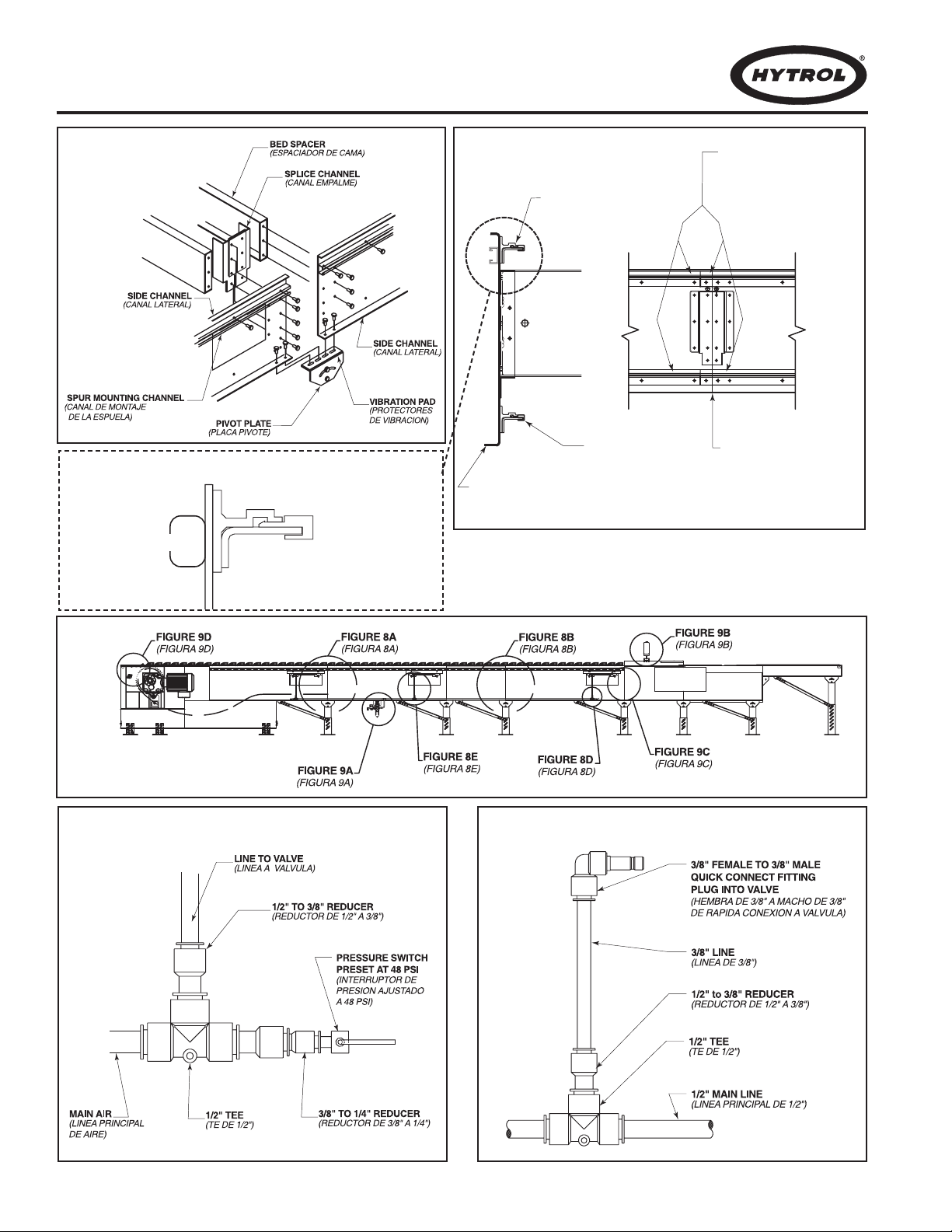
Attach supports and vibration pads to all conveyor sections
shown in Figures 6A and 8A. Adjust elevation to required
height. Hand tighten bolts only at this time.
During installation, check to make sure each bed section is
square. Measure the diagonals from corner to corner of the
frame. If they are not equal the frame must be squared. Attach
a come-along or some other suitable pulling device across
longest corners and pull until the section is square.
Place the infeed (tail) section in position.
Install remaining sections, placing end without support on
extended pivot plate of previous section (Figure 6A).
Fasten sections together with splice plates and pivot plates.
(Figure 8A). Hand tighten bolts only at this time.
Check to see that conveyor is level across the width and length
of unit. Adjust supports as necessary.
After all sections have been squared and levelled, tighten all
splice channels and support mounting bolts and lag support to
the floor.
Check alignment of wearstrip at all section joints. Sand
wearstrip as necessary to provide a smooth wear surface
(Figure 8B).
Starting on the infeed end, fasten bearing profile to wearstrip
guide using rubber mallet to force the profile edge under the
wearstrip (Figure 8B). Glue infeed end of profile to the support
angle with loctite # 401 or 454 adhesive.
Fasten 1/2” main air line to bottom of conveyor channel with
cable ties (Figures 8C & 9A). Connect 3/8”air lines at divert
switches as shown in Figures 8D & 8E.
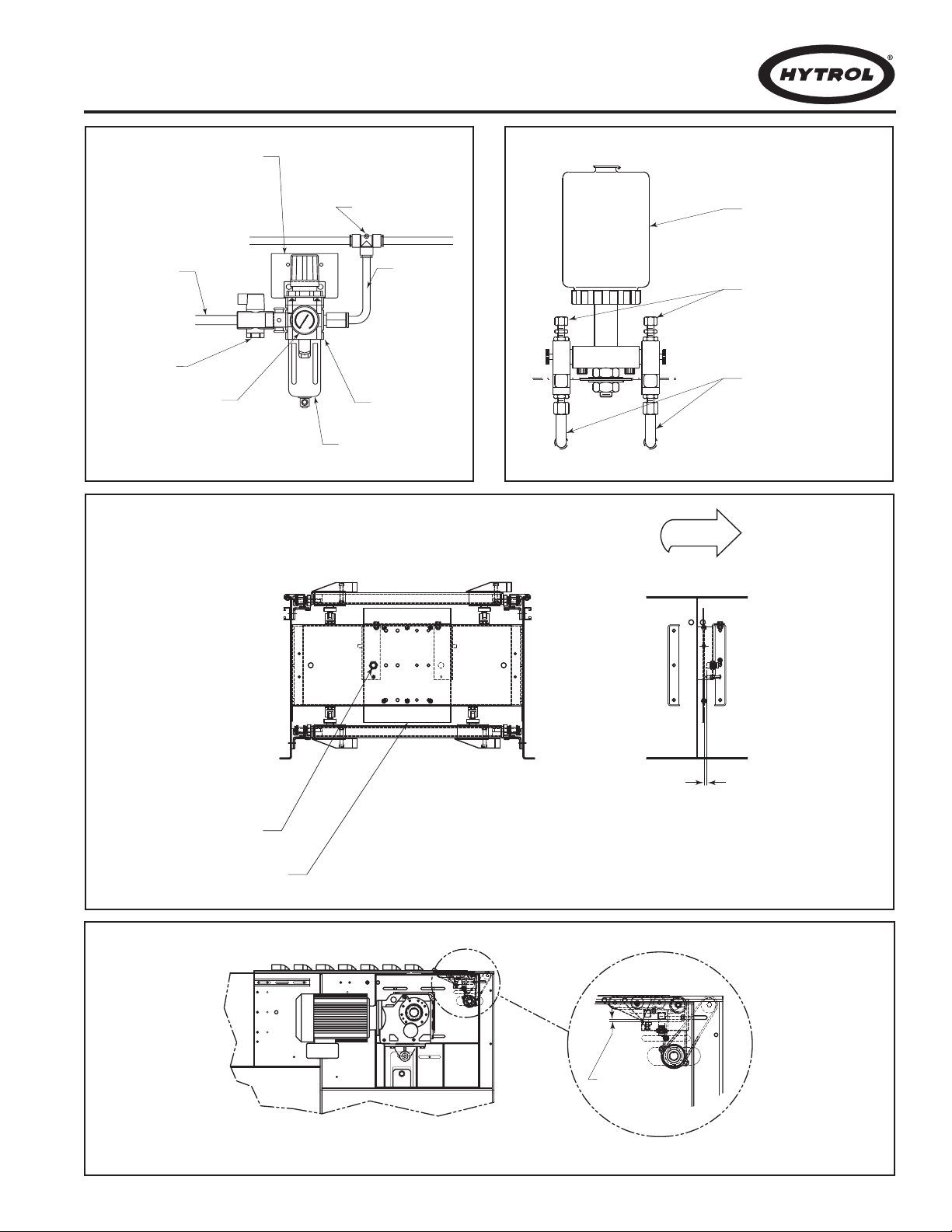
Connect main air line to the Filter/Regulator, (Figure 9A) Set
regulator to working pressure of 60 P.S.I. Install low pressure
switch, at farthest point from regulator (Figure 8D).
Install electrical controls and wire motor. Verify correct motor
rotation at this time. See Page 10 for electrical control
information.
Check each divert switch to see that it is operating properly.
This must be done before carrying chains are installed. See
instructions on Page 20.
Check proximity switch clearance at each internal safety switch
(Figure 9C). Adjust if necessary.
Install carrying chains per instructions on Page 22.
Adjust pop-up roller assembly at discharge end to optimize
transition of packages from the ProSort to the take away
conveyor. Set pop-up roller proximity switch per Figure 9D.
Install chain oiler at infeed and connect to oil lines as shown in
Figure 9B. Refer to the Lubrication section, page 13 for type of
oil required. After mounting, the oiler will need to be adjusted
for proper oiling of mounting chains. Adjustment may be made
using a combination of solenoid activation time and flow
adjustment screws. (A good rule of thumb for solenoid
adjustment is to turn the oiler on for one complete chain
revolution for every 2 hours of sorter operation.) The chain on
the divert side will typically need slightly more oil which may be
accomplished using the flow adjustment screws. CAUTION:
Do not allow oil to drip on floor.
Locate spurs per instructions on Page 24.
1. . .
2. . .
3. . .
4. . .
5. . .
6. . .
7. . .
8. . .
9. . .
10. . .
11. . .
12. . .
13. . .
14. . .
15. . .
16. . .
17. . .
18. . .
19. . .
Marque con tiza una línea en el suelo para ubicar el centro del
transportador.
Una los soportes y los protectores de vibración a las secciones (Figuras 6A
y 8A).Ajústelos a la altura requerida.Apriete los tornillos manualmente.
Durante la instalación revise que cada sección de cama esté escuadrada.
Durante la instalación, revise que cada sección de transportador está
escuadrada. Mida las diagonales de esquina a esquina del marco y
escuadre si es necesario. Utilice un tirante de escuadre o algo similar para
escuadrar la sección.
Ponga la sección del extremo alimentador (cola) en posición.
Instale las secciones restantes poniendo el extremo sin soporte en la placa
pivote de la sección anterior (Fig. 6A).
Sujete las secciones con placas de unión y pivote (Fig 8A).Apriete los tornillos
manualmente.
Revise si el transportador esta nivelado a lo ancho y largo de la unidad.
Ajuste los soportes como sea necesario.
Después de que todas las secciones hayan sido escuadradas y niveladas
apriete los empalmes de extremo y los tornillos de montaje del soporte.
Ancle el soporte al suelo.
Revise la alineación de las guías de cadena en todas las uniones. Lije las
guías lo necesario para obtener una superficie suave (Fig. 8B).
Empezando desde el extremo alimentador asegure el perfil del rodamiento
a la guía de la cadena usando un martillo de hule para forzar el perfil
debajo de la guía (Fig.8B).Pegue el perfil del extremo alimentador al ángulo
de soporte con el adhesivo loctite # 401 o 454.
Sujete la línea principal de aire de 1/2” a la parte inferior del canal del
transportador con cables de unión (Fig. 8C). Conecte las líneas de aire de
3/8” a los en los interruptores desviadores (Fig. 8D & 8E).
Conecte la línea principal de aire al Filtro/Regulador (Fig. 9A ). Ajuste el
regulador a una presión de 60 PSI. Instale el interruptor de baja presión lo
más alejado posible del regulador (Fig. 8D).
Instale controles eléctricos y el cableado del motor. Verifique la correcta
rotación del motor.Ver Pag. 10 para información eléctrica.
Revise cada interruptor desviador asegurándose de que funcione
correctamente. Esto debe hacerse antes de instalar las cadenas.Ver Pág.20.
Revise que el interruptor de proximidad esté despejado en cada terminal
de seguridad (Fig 9C).Ajuste si es necesario.
Instale las cadenas; instrucciones en la Pag. 22.
Ajuste el ensamble pivote de los rodillos de transición en la zona de
descarga para optimizar la transición de paquetes del ProSort al
transportador saliente. Ajuste el interruptor de proximidad del ensamble
pivote (Fig. 9D).
Instale el lubricador de cadena en el extremo alimentador y conecte a las
líneas de aceite (Fig.9B).Refiérase a la sección de lubricación (Pág. 13) para
el tipo de aceite requerido. Después de instalado, el lubricador necesita ser
ajustado para la apropiada lubricación de las cadenas. Se puede ajustar
combinando el ciclo de activación del solenoide y los tornillos de ajuste del
flujo. (para un buen ajuste del solenoide, el lubricador debe activarse
durante una revolución completa de cadena cada 2 hrs de operación del
sorter). La cadena del lado desviador usualmente necesita más aceite que
puede suministrarse por medio de los tornillos de ajuste del flujo.
PRECAUCION: No permita que el aceite gotee en el piso.
Coloque las espuelas. Instrucciones en la página 24.
● Conveyor Set-Up ● Montaje
1. . .
2. . .
3. . .
4. . .
5. . .
6. . .
7. . .
8. . .
9. . .
10. . .
11. . .
12. . .
13. . .
14. . .
15. . .
16. . .
17. . .
18. . .
19. . .

8
SECTION JOINT
(UNION DE SECCIONES)
BEARING PROFILE
(PERFIL DEL
RODAMIENTO)
CONVEYOR CHANNEL
(CANAL DEL
TRANSPORTADOR)
WEARSTRIP CHAIN GUIDE
(GUIA DE CADENA)
CHAIN GUIDESMUST BE
EVEN AT JOINT
(LASGUIASDE CADENA
DEBEN SER UNIFORMES
EN LA UNION)
FIGURE 8A FIGURE 8B
FIGURE 8D FIGURE 8E
IN
FIGURE 8C
END SWITCH
(INTERRUPTOR
EXTREMO)
INTERMEDIATE SWITCHES
(INTERRUPTORES INTERMEDIOS)
WEARSTRIP CHAIN GUIDE DETAIL

9
AIR SUPPLY TO
AIR VALVES
(SUMINISTRO D
E
AIRE A LAS
VALVULAS)
1/2" UNION TEE
(UNION TE DE 1/2")
BOWL GUARD
(TAZON PROTECTOR)
FILTER/REGULATOR
(REGULADOR/FILTRO)
GAUGE
(MEDIDOR)
MAIN AIR
SUPPLY
LINE
(SUMINISTRO
PRINCIPAL
DE AIRE)
MOUNTING BRACKET
(FASTEN TO
CONVEYOR CHANNEL)
(PLACA DE MONTAJE
[SUJETAR AL CANAL
DEL TRANSPORTADOR])
LOCK-OUT VALVE
(VÁLVULA DE BLOQUEO)
OIL CUP
(RECIPIENTE
DE ACEITE)
ADJUSTMENT SCREWS
(TORNILLOSDE AJUSTE)
OIL LINESTO BRUSHES
(LINEASDE ACEITE
A BROCHAS)
FLOW
(FLUJO)
PROXIMITY SWITCH
(INTERRUPTOR DE PROXIMIDAD)
SWITCH SENSOR
(SENSOR DEL INTERRUPTOR)
(3/16" DEL FRENTE DEL PROX
A LA PLACA DE METAL)
3/16" FROM PROX FACE
TO METAL PLATE
SPUR SIDESWITCH SIDE
(LADO DEL INTERRUPTOR) (LADO DE LA ESPUELA)
1/4" FROM PROX
TO TUBE
(1/4” DEL INTERRUPTOR
DE PROXIMIDAD AL TUBO)
FIGURE 9A FIGURE 9B
FIGURE 9C
FIGURE 9D

WARNING!
Electrical controls shall be installed and wired by a qualified
electrician. Wiring information for the motor and controls
are furnished by the equipment manufacturer.
CONTROLS
Electrical Code: All motor controls and wiring shall conform to
the National Electrical Code (Article 670 or other applicable
articles) as published by the National Fire Protection Association
and as approved by the American Standards Institute, Inc.
CONTROL STATIONS
A) Control stations should be so arranged and located that the
operation of the equipment is visible from them, and shall be
clearly marked or labeled to indicate the function controlled.
B) A conveyor which would cause injury when started shall not
be started until employees in the area are alerted by a signal or
by a designated person that the conveyor is about to start.
When a conveyor would cause injury when started and is
automatically controlled or must be controlled from a remote
location, an audible device shall be provided which can be clearly
heard at all points along the conveyor where personnel may be
present. The warning device shall be actuated by the controller
device starting the conveyor and shall continue for a required
period of time before the conveyor starts. A flashing light or
similar visual warning may be used in conjunction with or in place
of the audible device if more effective in particular circumstances.
Where system function would be seriously hindered or
adversely affected by the required time delay or where the intent
of the warning may be misinterpreted (i.e., a work area with
many different conveyors and allied devices), clear, concise, and
legible warning shall be provided. The warning shall indicate that
conveyors and allied equipment may be started at any time, that
danger exists, and that personnel must keep clear. The warnings
shall be provided along the conveyor at areas not guarded by
position or location.
C) Remotely and automatically controlled conveyors, and
conveyors where operator stations are not manned or are
beyond voice and visual contact from drive areas, loading areas,
transfer points, and other potentially hazardous locations on the
conveyor path not guarded by location, position, or guards, shall
be furnished with emergency stop buttons, pull cords, limit
switches, or similar emergency stop devices.
All such emergency stop devices shall be easily identifiable in
the immediate vicinity of such locations unless guarded by
location, position, or guards. Where the design, function, and
operation of such conveyor clearly is not hazardous to personnel,
an emergency stop device is not required.
The emergency stop device shall act directly on the control
¡ADVERTENCIA!
Los controles eléctricos deben ser conectados e instalados por un
electricista calificado. La información sobre el cableado del motor y
los controles será proporcionada por el fabricante del equipo.
CONTROLES
Código Eléctrico:Todos los controles del motor y las conexiones deben
ajustarse al “National Electrical Code“ (Artículo 670 u otros artículos
aplicables) como fué publicado por la “National Fire Protection
Association” y aprobado por el “American Standards Institute, Inc.”
ESTACIONES DE CONTROL
A) Las estaciones de control deberán estar arregladas y ubicadas de tal
forma que el funcionamiento del equipo sea visible desde ellas y deberán
estar claramente marcadas o etiquetadas para indicar la función
controlada.
B) Un transportador que pueda causar lesiones cuando es puesto en
marcha, no deberá ponerse en funcionamiento hasta que los trabajadores
en el área sean alertados por una señal o por una persona designada que
indique que el transportador está a punto de arrancar.
Cuando un transportador puede causar lesiones al arrancar y es
controlado automáticamente, controlado desde una locación lejana, se
deberá proporcionar un dispositivo sonoro el cual pueda ser escuchado
claramente en todos los puntos a lo largo del transportador donde el
personal pueda estar presente. El dispositivo de advertencia deberá ser
activado por el dispositivo de arranque del transportador y deberá
continuar sonando por un determinado periodo de tiempo antes de que
el transportador empiece a funcionar. Una luz intermitente o una
advertencia visual similar puede ser utilizada con o en lugar del dispositivo
sonoro si es más efectivo en circunstancias particulares.
Cuando el funcionamiento del sistema pueda ser seriamente
obstruído o adversamente afectado por el tiempo de retardo requerido, o
cuando el intento de advertencia pueda ser mal interpretado (ej., un área
de trabajo con diversas líneas de transportadores y con dispositivos de
advertencia relacionados), advertencias claras, concisas y legibles deberán
ser proporcionadas. Las advertencias deben indicar que los
transportadores y los equipos relacionados pueden ser puestos en marcha
en cualquier momento, que existe un peligro y que el personal debe
mantenerse alejado. Estas advertencias deben ser proporcionadas a lo
largo del transportador en áreas que no sean protegidas por su posición
o su ubicación.
C) Los transportadores controlados automáticamente y desde estaciones
lejanas, y los transportadores donde las estaciones de funcionamiento no
estén controladas por una persona o estén mas allá del alcance de la voz
y del contacto visual de las áreas de conducción, áreas de carga, puntos
de transferencia y otros sitios potencialmente peligrosos localizados en la
trayectoria del transportador que no tenga protección, ya sea dada por
posición, ubicación, o guardas, deberán ser equipados con interruptores de
parada de emergencia, cordones de parada de emergencia, interruptores
10
● Electrical Equipment ●Equipo Eléctrico

11
of the conveyor concerned and shall not depend on the stopping
of any other equipment. The emergency stop devices shall be
installed so that they cannot be overridden from other locations.
D) Inactive and unused actuators, controllers, and wiring should
be removed from control stations and panel boards, together
with obsolete diagrams, indicators, control labels, and other
material which serve to confuse the operator.
SAFETY DEVICES
A) All safety devices, including wiring of electrical safety devices,
shall be arranged to operate in a “Fail-Safe” manner, that is, if
power failure or failure of the device itself would occur, a
hazardous condition must not result.
B) Emergency Stops and Restarts. Conveyor controls shall be so
arranged that, in case of emergency stop, manual reset or start at
the location where the emergency stop was initiated, shall be
required of the conveyor(s) and associated equipment to resume
operation.
C) Before restarting a conveyor which has been stopped
because of an emergency, an inspection of the conveyor shall be
made and the cause of the stoppage determined. The starting
device shall be locked out before any attempt is made to remove
the cause of stoppage, unless operation is necessary to
determine the cause or to safely remove the stoppage.
Refer to ANSI Z244.1-1982, American National Standard for
Personnel Protection – Lockout/Tagout of Energy Sources –
Minimum Safety Requirements and OSHA Standard Number 29
CFR 1910.147 “The Control of Hazardous Energy
(Lockout/Tagout).”
de límite o dispositivos similares para paradas de emergencia.
Todos estos dispositivos de parada de emergencia deberán ser
fácilmente identificables en las cercanías inmediatas a estos puntos
potencialmente peligrosos, a no ser que estén protegidos dada su
ubicación, posición o protegidos con guardas. Donde el diseño, el
funcionamiento, y la operación de tales transportadores no represente
un claro peligro para el personal, no se requieren los dispositivos de
parada de emergencia.
El dispositivo de parada de emergencia deberá actuar directamente
en el control del transportador concerniente y no deberá depender de
la parada de cualquier otro equipo. Los dispositivos de parada de
emergencia deberán ser instalados de tal forma que no puedan ser
anulados desde otras localidades.
D) Los dispositivos, controles desactivados o en desuso y las conexiones,
deberán ser removidos de las estaciones de control y de los tableros de
mando, junto con los diagramas, indicadores, etiquetas de control y otros
materiales obsoletos, los cuales se prestan para confundir al operador.
DISPOSITIVOS DE SEGURIDAD
A) Todos los dispositivos de seguridad, incluyendo la conexión de
dispositivos eléctricos, deben ser dispuestos para operar en una manera
de “autoprotección”; es decir, si se presenta una pérdida de corriente o
un fallo en el mismo dispositivo, no debe presentarse una situación
peligrosa.
B) Paradas de Emergencia y Reactivadores. Los controles del
transportador deberán estar dispuestos de tal manera que en caso de
una parada de emergencia, se requiera un activador o arrancador
manual en la ubicación donde la parada de emergencia se presenta
para reanudar la operación del transportador o transportadores y el
equipo asociado.
C) Antes de reiniciar un transportador que ha sido detenido por una
emergencia, debe revisarse y determinar la causa de la parada. El
dispositivo de arranque deberá ser bloqueado antes de intentar corregir
el problema, a no ser que la operación del transportador sea necesaria
para determinar la causa o para solucionar el problema de la parada
sin ningún peligro.
Refiérase a ANSI Z244.1-1982, “American National Standard for
Personnel Protection” - Lockout/Tagout of Energy Sources - Minimum
Safety Requirements and OSHA Standard Number 29 CFR 1910.147
“The Control of Hazardous Energy (Lockout/Tagout).”

12
OPERATION
A) Only trained employees shall be permitted to operate conveyors.Training
shall include instruction in operation under normal conditions and emergency
situations.
B) Where employee safety is dependent upon stopping and/or starting devices,
they shall be kept free of obstructions to permit ready access.
C) The area around loading and unloading points shall be kept clear of
obstructions which could endanger personnel.
D) No person shall ride the load-carrying element of a conveyor under any
circumstances unless that person is specifically authorized by the owner or
employer to do so. Under those circumstances, such employee shall only ride a
conveyor which incorporates within its supporting structure, platforms or
control stations specifically designed for carrying personnel. Under no
circumstances shall any person ride on any element of a vertical conveyor.
Owners of conveyors should affix warning devices to the conveyor reading Do
Not Ride Conveyor.
E) Personnel working on or near a conveyor shall be instructed as to the
location and operation of pertinent stopping devices.
F) A conveyor shall be used to transport only material it is capable of handling
safely.
G) Under no circumstances shall the safety characteristics of the conveyor be
altered if such alterations would endanger personnel.
H) Routine inspections and preventive and corrective maintenance programs
shall be conducted to insure that all safety features and devices are retained and
function properly.
I) Personnel should be alerted to the potential hazard of entanglement in
conveyors caused by items such as long hair, loose clothing, and jewelry.
J) As a general rule, conveyors should not be cleaned while in operation.Where
proper cleaning requires the conveyor to be in motion and a hazard exists,
personnel should be made aware of the associated hazard.
OPERACION
A) Solo se deberá permitir operar los transportadores a empleados
entrenados. El entrenamiento debe incluir instrucciones de operación
bajo condiciones normales y en situaciones de emergencia.
B) Cuando la seguridad de los trabajadores dependa de dispositivos de
parada y/o arranque, tales dispositivos deberán mantenerse libres de
obstrucciones para permitir un acceso rápido.
C) El área alrededor de los puntos de carga y descarga deberá
mantenerse libre de obstrucciones, las cuales podrían poner en peligro
al personal.
D) Ninguna persona deberá subirse en la parte de
conducción de carga de un transportador bajo ninguna circunstancia al
menos que esta persona sea autorizada por el dueño o por el
supervisor. Bajo estas circunstancias, el empleado deberá subirse
solamente en un transportador que tenga incorporadas dentro de su
estructura, plataformas o estaciones de control especialmente
diseñadas para el traslado de personal. Bajo ninguna circunstancia,
persona alguna deberá subirse en cualquier parte de un transportador
vertical. Los dueños de los transportadores deberán añadir señales de
advertencia al transportador con el texto: "No subirse en el
Transportador".
E) El personal que esté trabajando en o cerca al transportador, deberá
ser instruído en cuanto a la ubicación y operación de los dispositivos
pertinentes de parada.
F) Un transportador deberá ser utilizado para transportar solamente
los productos que este esté en capacidad de manejar con seguridad.
G) Bajo ninguna circunstancia las características de seguridad de un
transportador deberán ser alteradas si tales alteraciones pudieran
poner en peligro al personal.
H) Inspecciones rutinarias deberán llevarse a cabo al igual que
programas de mantenimiento preventivos y correctivos, con la finalidad
de asegurar que todos los dispositivos y medidas de seguridad sean
conservados en buen estado y funcionen correctamente.
● Conveyor Start-Up
Before conveyor is turned on, check for foreign objects that may have
been left inside conveyor during installation. These objects could cause
serious damage during start-up.
After conveyor has been turned on and is operating, check motors,
reducers, and moving parts to make sure they are working freely.
●Arranque del Transportador
¡PRECAUCION!
Debido a la cantidad de partes en movimiento del transportador,
todo el personal en el área del transportador necesita ser
advertido de que este está a punto de ponerse en marcha.
Antes de poner en marcha el transportador, revise si hay objetos ajenos que
puedan haber sido dejados dentro del transportador durante la instalación.
Estos objetos pueden causar serios daños en el arranque.
Después de poner en marcha el transportador y esté operando, verifique los
motores, reductores y partes en movimiento para estar seguro de que están
trabajando libremente.
CAUTION!
Because of the many moving parts on the conveyor, all
personnel in the area of the conveyor need to be warned
that the conveyor is about to be started.
● Operation Safety Precautions ●Medidas de Seguridad en la
Operación

13
MAINTENANCE MANTENIMIENTO
A) Maintenance, such as lubrication and adjustments, shall be
performed only by qualified and trained personnel.
B) It is Important that a maintenance program be established to insure
that all conveyor components are maintained in a condition which does
not constitute a hazard to personnel.
C) When a conveyor is stopped for maintenance purposes, starting
devices or powered accessories shall be locked or tagged out in
accordance with a formalized procedure designed to protect all person
or groups involved with the conveyor against an unexpected start.
D) Replace all safety devices and guards before starting equipment for
normal operation.
E) Whenever practical, DO NOT lubricate conveyors while they are
in motion. Only trained personnel who are aware of the hazard of the
conveyor in motion shall be allowed to lubricate.
SAFETY GUARDS
Maintain all guards and safety devices IN POSITION and IN SAFE
REPAIR.
WARNING SIGNS
Maintain all warning signs in a legible condition and obey all warnings.
See Page 3 of this manual for examples of warning signs.
A) El mantenimiento, tal como lubricación y ajustes, deberá ser realizado solamente
por personal calificado y entrenado.
B) Es importante que se establezca un programa de mantenimiento para asegurar
que todos los componentes del transportador sean mantenidos en condiciones que
no constituyan un peligro para el personal.
C) Cuando un transportador está parado por razones de mantenimiento, los
dispositivos de arranque o accesorios motorizados deberán ser asegurados o
desconectados conforme a un procedimiento formalizado, diseñado para proteger a
toda persona o grupos involucrados con el transportador, de un arranque inesperado.
D) Antes de poner en marcha el equipo en una operación normal, vuelva a colocar
todos los dispositivos de seguridad y las guardas.
E) Siempre que sea práctico, NO lubrique los transportadores mientras se
encuentren en movimiento. Solo el personal entrenado que tenga conocimiento de los
peligros del transportador en movimiento, se le permitirá hacer la lubricación.
PROTECCIONES DE SEGURIDAD
Mantenga todas las guardas y dispositivos de seguridad EN SU POSICION y EN
BUENAS CONDICIONES.
SEÑALES DE ADVERTENCIA
Mantenga todas las señales de advertencia en buenas condiciones y obedézcalas.
Remítase a la página 3 de este manual para ver ejemplos de señales de
advertencia.
● Maintenance Safety Precautions ● Medidas de Seguridad en el Mantenimiento
● Lubrication ●Lubricación
Ambient Temperature SAE ISO
Degrees F
20-40 20 46 or 68
40-100 30 100
Temperatura Ambiente SAE ISO
(Grados Fº) (Grados Cº)
20-40 -07 – 04 20 46 o 68
40-100 04 – 38 30 100
BEARINGS
A) NO GREASE FITTING—Prelubricated—No lubrication
required.
B) WITH GREASE FITTING—Relubricate approximately every 10
to 12 weeks with lithium base grease suitable for ball bearing service.
RECOMMENDED CHAIN LUBRICANT
A good grade of clean petroleum or synthetic oil is recommended.
See chart for proper viscosity.
REDUCERS
See recommendations by manufacturer.
RODAMIENTOS
A) NO GREASE FITTING—Prelubricados—No se necesita lubricación.
B)WITH GREASE FITTING—Lubricar cada 10 a 12 semanas con aceite
a base de litio apropiado para los balines de los rodamientos
LUBRICANTE DE CADENA RECOMENDADO
Se recomienda aceite a base de petroleo de alto grado o sintético.Ver recuadro
para la viscosidad apropiada.
REDUCTORES
Refiérase a las recomendaciones del fabricante.

14
A good software package is essential for the proper operation of
the ProSort sorter. With proper controls, the sorter will provide
accurate, efficient, reliable sorting for many years. Inadequate
controls, however, may result in poor sorter performance and
other mechanical failures of the sorter itself, including “crashes”.
Hytrol recommends using the Hytrol ProLogix software package.
Every sortation system is different, which means that the controls
for the system are custom and unique to that system. These
custom controls are provided either by Hytrol, the Hytrol
distributor or a third party.
Hytrol has built into the sorter some of the controls necessary
to operate the divert switches, eliminating the need to control
this function externally. Other electrical control components are
provided with the sorter to allow the external controls to
monitor critical items and to provide an interface between the
electrical controls and the mechanical sorter. Still other control
components must be provided by the supplier of the custom
controls package to insure proper sorter operation.
This section of the manual includes the following information for
the custom controls provider:
● Controlling the ProSort ●Controlando el ProSort
Un buen software es esencial para la operación correcta del ProSort. Con
los controles correctos, el clasificador proveerá precisión, eficiencia y
confianza por muchos años. Por el contrario controles inadecuados
pueden ser la causa de un desempeño inadecuado del sorter y son la
causa principal de colapsos y fallas mecánicas del mismo.
Cada sistema de clasificación es diferente, por lo tanto cada sistema
tiene controles únicos y adecuados para ese sistema. Estos controles son
usualmente proporcionados por el distribuidor Hytrol, el usuario o por un
tercero.
Hytrol ha incorporado en el clasificador algunos controles necesarios
para operar los interruptores desviadores, eliminando la necesidad de
controlarlos externamente. Otros componentes del control eléctrico
también se proporcion con el clasificador para permitir que controles
exteriores detecten detalles críticos y para una interface entre los
controles eléctricos y el sorter mecánico. Aún asi, otros componentes de
control deben ser proporcionados por el proveedor del paquete
especifico de control para asegurar una operación de clasificación
adecuada.
Esta sección del manual incluye la siguiente información para el
proveedor de los controles:
A description of the divert switch control components
supplied, their function, and how to interface with them.
A description of the other control components provided
with the sorter and their intended function.
A description of control components that are not included
with the sorter that must be provided by the controls
supplier.
Some control do’s and dont’s to assist in the design and
installation of the controls package.
1. . .
2. . .
3. . .
4. . .
Una descripción de los componentes del control proporcionado del
interruptor desviador y sus funciones.
Una descripción de los otros componentes de control provistos con
el sorter y su función principal.
Una descripción de los componentes de control que no son incluídos
con el sorter y que deben ser proporcionados por el proveedor de
los controles.
Algunas recomendaciones en que y que no hace, con controles para
ayudarlo en el diseño e instalación del paquete de control.
1. . .
2. . .
3. . .
4. . .
Please read this section thoroughly and share this information
with the controls provider.
DIVERT SWITCH CONTROL
Proper control of the divert switch is critical to the safe and
reliable operation of the sorter. Failure to properly control the
divert switch is one of the most common causes of switch
damage and can cause “crashes.”
The divert switch functions similar to a switch on a train track to
cause the divert shoes to travel either in a straight-through,“non-
divert” track or diagonally across the sorter along a “divert
track” to push product off of the sorter. When the switch is in
the “home” position, the divert shoes travel through the switch
along the straight-through track. When the switch is in the
“divert” position, the shoes are caused to move along the divert
track.
The transition of the switch between the “home” and “divert”
positions must be accurately timed to prevent sorter crashes. Just
as a train track switch cannot be safely operated while a train is
passing through the switch, the divert switch cannot be safely
operated while a divert shoe is passing through the switch. If the
movement of the switch mechanism is not timed to occur only
when no shoe is present in the switch, the guide pin of
the shoe may collide with the point of the divert block, resulting
in damage to the switch and potentially costly downtime.
Por favor lea esta sección completamente y compártala con el proveedor
de los controles.
CONTROL DEL INTERRUPTOR DESVIADOR
Un control apropiado del interruptor desviador es fundamental para
lograr una operación del sorter segura y confiable. No controlar
correctamente el interruptor desviador es una de las causas más
comunes de daños en el mismo y de “colapsos” durante la operación.
El interruptor desviador funciona similarmente a un interruptor en la vía
del tren, permitiendo que los bloques desviadores viajen tanto en
dirección rectilínea por la vía “sin-desviación”, o diagonalmente a través
del sorter por la “vía de desviación” empujando el producto fuera del
mismo. Cuando el interruptor está en posición “standard”, los bloques
desviadores viajan en dirección rectilínea. Cuando el interruptor está en
posición “desviar”, hace que los bloques viajen por la vía de desviación.
La transición del interruptor entre las posiciones “standard” y “desviar”
debe ser perfectamente cronometrada para evitar colapsos durante la
clasificación. De la misma forma que un interruptor de cambio de vía de
tren no puede ser operado en forma segura mientras el tren está
pasando, el desviador no puede ser operado seguramente cuando un
bloque interruptor pasa a través del mismo. Si el mecanismo del
interruptor no está programado para actuar solamente cuando
ningún bloque desviador está presente en el interruptor,

15
The ProSort has two control components at each divert switch
that work together to accurately time the divert switch
movement or operation, eliminating the need for the controls
provider to do so. These components are the smart prox and
the high-speed solenoid air valve.
SMART PROX
The “smart prox” is a special inductive proximity sensor
developed exclusively for Hytrol that has the “intelligence”
needed to control the switch timing built-in. The prox plugs to
the y-cable. See Figure 15A.
Y Cable
The y-cable is used to connect the smart prox, solenoid air valve
and the system controls. The male micro cord set from the smart
prox connects to the terminal #1 of the y-cable. The pico pigtail,
off the y-cable, connects to the male plug on the solenoid air
valve at divert switch. The micro cord set with female end, plugs
to terminal #2 of the y-cable. The leads from the terminal #2
cord set have the following functions (Fig. 15A). NOTE:Y-cable
not used on dual divert sections.
Brown—+24VDC power input to the prox.
Blue—Ground (-) lead for the prox.
Gray—Divert enable input lead for the prox. When a 24VDC
(high) signal is given to this lead by the system controls, the prox
waits for the next time it detects a divert shoe, at which time it
provides a 24VDC output through the y-cable to the high speed
solenoid air valve.The solenoid air valve then causes the switch
to move to “divert” position. All shoes traveling through the
switch will then follow the divert track as long as the enable
signal is active (held high). When the divert signal is removed
el pin guia del bloque puede chocar con el punto inferior del bloque del
interruptor resultando en daños al interruptor y potencialmente en
paradas costosas.
El ProSort tiene dos componentes de control en cada desviador que
trabajan en conjunto para cronometrar con precisión el movimiento u
operación, eliminando la necesidad de que el proveedor del control lo
haga. Estos componentes son el “smart prox” y la válvula
solenoide de aire de alta velocidad.
“SMART PROX”
El “smart prox” es un sensor de proximidad inductivo diseñado
exclusivamente para Hytrol, el cual tiene la “inteligencia” para controlar
la regulación del tiempo del interruptor. El prox se conecta al cable Y.
Ver figura 15-A:
Cable Y
El cable Y se usa para conectar el “smart prox”, la válvula solenoide de
aire y los controles del sistema. El set macho de cables que se origina
en el “smart prox” se conecta al terminal #1 del cable Y. La “cola” del
cable Y se conecta al enchufe macho en la váluva solenoide de aire del
interruptor desviador. El set hembra de cables se conecta al terminal #2
del cableY. Los conductores del set del terminal #2 tienen las siguientes
funciones. (Fig 15A) NOTA: El cable Y no se usa en secciones
desviadoras dobles.
Café—Potencia de entrada al prox de +24VDC.
Azul—Conductor tierra (-) para el prox.
Gris—Conductor para el prox que habilita el interruptor. Cuando una
señal de 24VDC (alta) es dada al conductor por controles del sistema,
el prox espera que se detecte el siguiente bloque desviador y provee una
salida de 24VDC a la válvula solenoide de aire a través del conductor
blanco. La válvula solenoide se encarga en este momento de hacer que
SMART
PROX
SOLENOID
VALVE
SMART PROX
SMART PROX
AND VALVE
CONNECTION
FOR
SINGLE-SIDED
SORTERS
ONLY
SMART PROX
TO SOLENOID
"Y" CONNECTOR
032.21124
SMART PROX
CORD SET
BROWN/CAFÉ
+24 VOLTSDC
DC COMMON
SMART PROX ENABLE
SMART PROX STATE
(NOT USED/SIN USAR)
BLUE/AZUL
GRAY/GRIS
BLACK/NEGROWHITE/BLANCO
12
(SMART PROX Y
CONEXION A
VALVULA SOLO PARA
SORTESDE LADO
SENCILLO)
(VALVULA
SOLENOIDE)
(SMART PROX Y
A SOLENOIDE
CABLE Y)
FIGURE 15A

Otros Componentes de Control Suministrados
con el Transportador
CONTROLADOR MOTRIZ DE FRECUENCIA VARIABLE
La unidad motriz de frecuencia variable (VFD) es un controlador de
motor que tiene dos funciones:
Refiérase al manual de instalación del VFD, proporcionado con el sorter
para conexiones e instrucciones de ajuste.
INTERRUPTOR DE PRESION DE AIRE
El interruptor es usado para detectar baja presión de aire (Fig. 8D).. La
operación del sorter con presión de aire menor que 50 PSI puede
causar cambios irregulares y daño potencial al interruptor. Si la presión
de aire se encuentra por debajo de este nivel, el sorter debe apagarse
hasta que la causa de la disminución de presión sea encontrada y
remediada.
El interruptor de presión provee una salida de tipo-contacto, la cual se
cierra con presiones de o mayores que a 48 PSI y se abre con presiones
menores. El proveedor de los controles deberá usar este interruptor para
monitorear la presión del aire en el sorter y deberá apagar el sorter si
una salida abierta (baja) es detectada en el interruptor de presión.
el interruptor desviador cambie a la posición “desviar”.Todos los bloques
viajando a lo largo del interruptor seguirán la vía desviadora mientras
la señal habilitadora esté activa (en alto). Cuando la señal desviadora es
removida (en bajo) el prox espera detectar el próximo bloque desviador,
cerrando la salida que va a la válvula solenoide. El interruptor desviador
regresará a la posición “standard” y los bloques siguientes seguirán la vía
recta “sin-desviación”. La señal habilitadora a este conductor
es la única señal que los controles del sistema deben
proporcionar al control del interruptor desviador.
Negro—Conductor de salida estándar del prox. Este conductor provee
una señal de 24VDC (alto) cada vez que el prox detecte un bloque
desviador. Esta es una salida opcional y debe ser usada a discreción del
proveedor de controles.
VALVULA SOLENOIDE DE AIRE DE ALTA VELOCIDAD
La válvula solenoide de aire se usa para recibir la señal de salida del
smart prox y proporciona aire al extremo apropiado del cilindro del
interruptor desviador para mover y mantener el interruptor ya sea en
posición “standard” o en “desviar”. La válvula está especialmente
diseñada para una operación de alta velocidad necesaria para un tiempo
exacto de desviación. Las dos entradas del solenoide son no polarizadas,
permitiendo que cualquier conductor sea usado como entrada o tierra
para la válvula. El solenoide requiere 24VDC, y 4W para operar. La
válvula es controlada directamente por el prox. El control directo de esta
válvula por el paquete de control es no es recomendado.
16
(taken low) the prox waits for the next time it detects a divert
shoe, at which time it will turn off the output to the solenoid air
valve. The switch then returns to the “home” position, and
subsequent shoes will follow the “non-divert” track. The
enable signal to this lead is the only signal that the
system controls must provide to control divert
switching.
Black—Standard prox output lead.This lead provides a 24VDC
(high) signal each time the prox detects a divert shoe.This is an
optional output and is to be used at the discretion of the controls
provider.
HIGH-SPEED SOLENOID AIR VALVE
The solenoid air valve is used to receive the smart prox output
signal and provide air to the proper end of the divert switch
cylinder to move and hold the switch in either the “home” or
“divert” positions.The valve used is specially designed for the high
speed operation necessary for proper divert switch timing.
The two inputs of the solenoid are non-polarized, allowing either
lead to be used as input or ground for the valve. The solenoid
requires 24VDC, 4W to operate.
The solenoid air valve is controlled directly by the smart prox.
Direct control of this valve by the controls package is not
required or advised.
Other Control Components Supplied with
the Conveyor
VARIABLE FREQUENCY DRIVE CONTROLLER
The variable frequency drive (VFD) is a motor controller that has
three functions:
Refer to the VFD manufacturer’s installation manual, provided
with the sorter, for wiring and adjustment instructions.
AIR PRESSURE SWITCH
The air pressure switch (Fig. 8D) is used to detect low operating
air pressure. Operation of the sorter at air pressures under 50
PSI can cause erratic switching and potential switch damage. If air
pressure falls below this level, the sorter must be shut down until
the cause of the pressure drop has been found and remedied.
The pressure switch provides a contact-type output which closes
at pressures at or above about 48 PSI and opens below that air
pressure.The system controls provider should use this switch to
monitor air pressure at the sorter and should shut down the
It provides a smooth acceleration of the drive motor,
allowing the sorter to slowly “ramp up” to full speed.This
protects the sorter components from the stress of a full-
speed start-up.
It allows the speed of the sorter to be adjusted to match
speed requirements of the system.Also, it allows the sorter
to be operated at a very slow speed during installation
“debugging” and when certain mechanical components are
checked after servicing.
It allows the sorter to be operated at a slower speed
during “off-peak” seasons, reducing energy consumption,
noise, and wear.
1. . .
2. . .
3. . .
Proporciona una aceleración suave del motor, permitiendo que el
sorter acelere suavemente hasta su máxima velocidad. Esto
protege los componentes del sorter de un esfuerzo en caso de un
arranque repentino.
Permite que la velocidad del sorter se ajuste hasta igualar los
requerimientos del sistema. También permite que el sorter se
opere lentamente durante la instalación y cuando ciertos
componentes mecánicos sean revisados.
Permite que el sorter se opere a baja velocidad en baja
temporada, reduciendo así el consumo de energia, el ruido y el
desgaste.
1. . .
2. . .
3. . .

17
Hay dispositivos de seguridad colocados en varios lugares del sorter para
indicar cuando un bloque desviador este fuera de lugar, cuando hay una
obstrucción en el sorter, o cuando algo haya ocurrido que pudiera causar
daño el sorter o peligro al personal. Estos interruptores de seguridad
usan interruptores normales de proximidad inductivos como el interface
eléctrico a los controles del sistema.
Hay dos tipos de interruptores de seguridad en el sorter:
El estado normal de salida de los interruptores de proximidad es “on”
(alto). Si un interruptor detecta un problema, la señal se cambia a “off ”
(bajo). El control del sistema debe estar configurado para ir a una
condición de “paro de emergencia” y apagar el sorter y el equipo
relacionado cuando sea corrija un problema. No se debe poner en
marcha hasta que el problema sea detectado y el interruptor de
proximidad que detectó el problema se encuentre de nuevo en “on.”
Refiérase al manual de instalación del interruptor de proximidad para
instrucciones de como conectarse, proporcionado con el sorter.
FOTO CELDA TENSION CATENARIA
La foto celda controla la cantidad de pandeo de la cadena que ocurre
en el área de la catenaria. La foto celda es un retro-reflector operando
con señal de luz, colocado en la catenaria; así que si los tubos
extendidos bajan más que el nivel marcado, el haz de la foto celda se
bloquea.
Los controles del sistema deben ser configurados de tal manera que
detengan el sorter cuando el haz se bloquea (la salida de la foto celda
es “off ”) e indiquen al operador que la cadena debe ser tensionada o
acortada antes de que el sorter continue operando.
Refiérase al manual de instalación de la foto celda, adjunto con el sorter,
para instrucciones de como conectarlo.
CODIFICADOR
El codificador viene incluido con el sorter para dar una señal que sirve
para rastrear el producto. El codificador da una señal de pulsación de
onda-cuadrada de diez transiciones de baja-a-alta y de alta-a-baja por
revolución del eje alimentador del sorter, para una resolución de veinte
pulsaciones por revolución. Esto equivale a una pulsación (sea 10 “altas”
y 10 “bajas”) por cada dos pulgadas de trayecto del sorter.
sorter if an open (low) output is detected from the pressure
switch.
Refer to the pressure switch manufacturer’s installation manual,
provided with the sorter, for wiring instructions.
SAFETY PROXIMITY SWITCHES
There are safety switch devices located at various locations in the
sorter to indicate when a divert shoe is out of place, an
obstruction has entered the sorter, or when some other event
has occurred that could cause damage to the sorter or danger to
personnel.These safety switches use normal inductive proximity
switches as the electrical interface to the system controls.
There are two types of safety switches in the sorter:
The normal state of the output of the safety proximity switches
is”on” (high). If a switch detects a problem the signal is changed
to “off” (low).The system controls must be configured to go to
an “emergency stop” condition and shut down the sorter and
related equipment when a problem is detected. Restart must not
be possible until the problem is corrected and the safety switch
that detected the problem is again “on” (high).
Refer to the proximity switch manufacturer’s installation manual,
provided with the sorter, for wiring instructions.
CATENARY TAKE-UP PHOTO-EYE
The catenary take-up photo-eye monitors the amount of chain
sag occurring in the drive’s catenary area. The photo-eye is a
retro-reflective, light-operated type, positioned in the catenary so
that if the carrying chains allow the slats to sag below a certain
level, the beam of the eye is blocked.
The system controls must be configured to stop the sorter when
the photo-eye beam is blocked (photo-eye output is “off” or
“low”) and provide an indication to the sorter operator that the
chains must be taken up or shortened before operating the
sorter further.
Refer to the photo-eye manufacturer’s installation manual,
provided with the sorter, for wiring instructions.
ENCODER
An encoder is included with the sorter to provide a pulse signal
Interruptores de seguridad de bloque son mecanismos dentro del
clasificador que detectan si un bloque está desalineado.También
sirven para detectar objetos ajenos que hayan caido en los tubos
extendidos y dentro del clasificador. Están hechos para detectar
problemas en ambas secciones del clasificador (ya sea la superior
o de retorno).
Hay un interruptor localizado en la zona de carga y de descarga
del clasificador. Hay interruptores adicionales cada 30 pies del
clasificador. Por ejemplo, un sorter de 30 pies de largo tendrá 3
interruptores; uno de 80 pies tendrá 4 interruptores y asi en
adelante. Estos interruptores adicionales están espaciados
igualmente a lo largo de toda la longitud del sorter.
El interruptor de seguridad de los rodillos de transición es usado
para detectar cuando los rodillos de transición en la zona de
descarga están “levantados”. Estos rodillos están diseñados para
levantarse si un objeto extraño o un bloque desviador suelto hace
contacto con ellos.
1. . .
2. . .
Shoe position safety switches are switch mechanisms inside
the sorter that trip if a divert shoe passes them that is not
in its proper track. They are also used to detect foreign
objects that might fall between the slats and enter the
interior of the sorter.They are made to detect problems on
both the upper and return portions of the sorter.
There is one shoe position safety switch located at the
infeed end and one at the discharge end of the sorter.
There are additional switches included for every 30 feet of
sorter length after the first 30 feet. For example, a sorter
50 feet long will have a total of 3 switches, a sorter 80 feet
long will have a total of 4 switches and so on. These
additional switches are spaced evenly along the sorter’s
length.
The pop-up transition roller safety switch is used to detect
when the transition rollers on the discharge end of the
sorter are in the “up” position. These rollers are designed
to pop up if a stray divert shoe or a foreign object makes
contact with them.
1. . .
2. . .
Refiérase al manual de instalación del interruptor de presión,
proporcionado con el sorter, para instrucciones de como debe ser
conectado.
INTERRUPTORES DE PROXIMIDAD DE SEGURIDAD

18
El codificador requiere 24VDC de potencia y provee una salida de
pulsación de 24VDC.
Refiérase al manual de instalación del codificador, provisto con el sorter,
para instrucciones de como conectar.
SOLENOIDE DE LUBRICADOR DE CADENA
El lubricador es utilizado para proporcionar una lubricación automática
de las cadenas durante la operación del sorter. Cuando la válvula
solenoide del lubricador recibe energía, el aceite de la reserva fluye por
gravedad a las válvulas de medición y luego a las brochas localizadas
sobre las cadenas de retorno del sorter.
Los controles del sistema deben ser configurados para activar el
solenoide del lubricador durante una revolución completa de las cadenas
cada dos horas de operación. La cantidad de aceite aplicada es
controlada por los torni-llos de medición (Vea la sección “Montaje” en
este manual).
El lubricador de cadena requiere una pontencia de 24VDC.
Componentes de Control no Suministrados con el
Transportador
Además de los componentes de control suministrados con el ProSort, hay
varios componentes que deben ser suministrados por el proveedor de los
controles del sistema. Hytrol recomienda el uso de los siguientes
componentes para prevenir daños en el sorter debido a obstrucción de
productos u otros problemas.
REGULADOR DE SOBRECARGAS DEL MOTOR
El regulador provee protección contra daños apagando el motor cuando
se detecta un aumento repentino de corriente. Al ajustar ligeramente el
límite de sobrecarga por encima de la potencia requerida para operar el
sorter, cualquier extra carga como una obstrucción o un mal
funcionaniento, hará que el sorter se detenga, posiblemente antes de
causar un daño significativo al equipo.
El regulador debe ser instalado en el panel de control para medir la
potencia correcta del motor.
FOTO CELDA
Las foto celdas son componentes comunes en los controles del sistema.
Hytrol recomienda que las foto celdas sean instaladas en los siguientes
lugares para que realicen las funciones descritas. Estas son algunas foto
celdas entre otras que se necesiten en el sistema.
Foto celda de Inducción—Una foto celda colocada en el punto
alimentador del sorter. Esta es usada para realizar las siguientes
funciones:
Avisar a los controles del sistema que un paquete particular ha
entrado en el sorter. Desde este punto en adelante, el paquete
debe ser rastreado usando las pulsaciones del codificador para
determinar cuando alcanza el punto de desviación asignado.
Medir la longitud del paquete para que los controles del sistema
puedan asignar el número correcto de bloques desviadores
necesarios para desviarlo. Nota: El número de bloques se asigna
de acuerdo a la longitud total del paquete más uno extra para
el extremo del mismo.
Revisar el espacio apropriado entre los paquetes para una
clasificación segura. Es importante revisar acá el espacio
correcto aunque ya haya sido establecido antes de llegar a este
punto, para asegurar que los paquetes estén espaciados
correctamente. Intentar clasificar los paquetes con poco espacio
1. . .
2. . .
3. . .
to be used for product tracking. The encoder provides a square-
wave pulse signal of 30 pulses per revolution of the sorter infeed
shaft. This equates to one pulse for every 1.75 inches of sorter
travel.
The encoder requires 24VDC power, and provides a 24VDC
pulse output.
Refer to the encoder manufacturer’s installation manual provided
with the sorter, for wiring instructions.
CHAIN OILER SOLENOID
The chain oiler is used to provide automatic lubrication of the
carrying chains during sorter operation.When the oiler solenoid
valve is energized, oil is allowed to gravity feed from the oiler
reservoir, through metering valves, to brushes located above the
return chains in the sorter.
The system controls should be configured to activate the chain
oiler solenoid for a duration equal to one complete revolution of
the carrying chains about every two hours of operation. The
actual amount of oil applied to the chains is controlled by the
metering screws (see “Conveyor Set-up” section of this manual).
The chain oiler solenoid requires 24VDC power to operate.
Control Components Not Supplied
with the Conveyor
In addition to the control components supplied with the ProSort
sorter, there are several components that must be supplied by the
system control provider. Hytrol recommends the following
control components be used to protect the sorter from damage
due to product jams or other problems.
ADJUSTABLE INSTANTANEOUS MOTOR
OVERLOADS
Instantaneous overloads provide protection against sorter “hang-
ups” by turning off the drive if a sudden increase in motor current
is detected. By adjusting the overload limit to slightly above the
power required to operate the sorter, any extra load on the
motor, such as would be caused by a product jam or switch
malfunction, would cause the sorter to stop, possibly before
significant damage is done to the equipment.
The instantaneous overloads should be installed in the control
panel for the sorter and sized for the proper power
requirements.
PHOTO-EYES
Photo-eyes are common components in systems controls. Hytrol
recommends that photo-eyes be installed at the following
locations to perform listed functions. These are, of course, in
addition to other photo-eyes needed in the system.
Induction Photo-eye—A photo-eye mounted at the infeed
point of the sorter. This eye is used to perform the following
functions:
Signal the system controls that a particular package has entered
the sorter. From this point forward, the package must be
tracked using the encoder pulses to determine when it reaches
the proper divert location.
Measure the length of the package so that the system controls
may assign the proper number of divert shoes to the package
1. . .
2. . .

Jam/Confirmation Photo-eye—Photo-eyes mounted on
each take-away spur of the sorter, as close to the sorter as
possible.These eyes perform two functions:
Full Line Photo-eye—Photo-eyes mounted on each divert
lane from the sorter, near the infeed end of that lane.These eyes
are used to signal the system controls that a particular divert lane
is full. The controls should then send any further packages
assigned to that lane to the recirculation line until the full line
photo-eye on that lane no longer indicates the full condition.
19
Foto celda de Línea Llena—Las foto celdas que son montadas en
las líneas desviadoras del sorter, lo más cerca posible al extremo
alimentador de las mismas, se encargadas de dar una señal a los
controles del sistema cuando una línea particular desviadoras está
llena. Los controles harán que los paquetes asignados a esta línea
recirculen hasta que la foto celda deje de indincar que la línea se
encuentra llena.
Foto celda de Confirmación/Obstrucción—Las foto celda se
coloca en las espuelas acopladas al sorter lo más cerca posible al mismo.
Esta foto celda tiene dos funciones:
Detectar un producto atorado en el punto de salida del sorter.
Si un paquete bloquea esta foto celda por más tiempo de lo que
le tomaría a este viajar y pasar la foto celda normalmente, esto
indica que el paquete se encuentra atorado. El sorter debe ser
detenido y la obstrucción removida antes de volver lo a poner en
marcha.
Confirmación de desviación. Si una señal de desviación es dada
para un punto particular de desviación ningún paquete es
detectado por la foto celda asociada, un error ha ocurrido. El
sorter debe ser detenido y el error detectado y corregido antes
de ponerlo en marcha.
1. . .
2. . .
entre ellos puede causar obstrucciones. Nota: El mínimo espacio
necesario para la clasificación de un paquete está en función del
ancho del mismo. Las siguientes tablas deben considearse al
asignar el gap apropiado.
* W = Ancho del Paquete
Minimum gap = Espacio mínimo
Nota: Cuando se clasifica hacia ambos lados, el espacio mínimo en la tabla
debe incrementarse en 6 pulgadas.
for diverting. Note: Shoes are to be assigned for the entire
length of the package plus one extra shoe is to be assigned to
the trailing end of the package.
Check for the proper gap between packages for safe sorting. It
is important to check for the proper gap here, even if it has
been set prior to this point, to insure that the packages are
truly spaced properly. Attempting to sort packages with too
little gap between them can cause jams.Note:The minimum gap
necessary for sorting a package is a function of the width of the
package. The charts below should be used in checking for
proper gap.
3. . .
ProSort 431 (30° Diverts)
ProSort 431 (30º Centros de Desvío)
0” < W ≤ 10” Minimum gap = 10”
10” < W ≤ 20” Minimum gap = 16”
20” < W ≤ 30” Minimum gap = 20”
30” < W ≤ 40” Minimum gap = 26”
ProSort 421 (22° Diverts)
ProSort 421 (22º Centros de Desvío)
0” < W ≤ 13” Minimum gap = 10”
13” < W ≤ 26” Minimum gap = 16”
26” < W ≤ 40” Minimum gap = 20”
* W = Package Width
Note:When sorting to both sides, the minimum gap from the above
charts must be increased by 6 in.
Detect a product jam at the sorter “exit point.” If a package
blocks this photo-eye for a longer time than it would take
for the package to travel past the photo-eye normally, this
indicates that the package is jammed.The sorter should be
stopped and the jam cleared before restarting the sorter.
Divert confirmation. If a divert signal is given to a particular
divert point, and no package is detected by the associated
jam/confirmation photo-eye, an error has occurred. The
sorter should be stopped and the error found and
corrected before restarting the sorter.
1. . .
2. . .

20
After all ProSort sections are installed and aligned, each divert
switch should be checked for proper operations as follows:
Before air pressure is supplied to the divert switch solenoid
air valve, manually pivot the switch back and forth between
the non-divert and divert position checking for a free and
smooth pivoting movement. Determine and remedy the
cause of any switch binding. For proper switch alignment
see figures 21A & 21B. If switch adjustment is necessary,
loosen the jam nut on the cylinder rod. Screw cylinder rod
into or out of rod end to adjust the switch and retighten
jam nut.
Turn air pressure on and verify that each divert switch is in,
or moves to, the home (non-divert) position (Figure 21A).
Check to insure that the smart prox is set properly. The
face of the prox should be set just out of the shoe pin guide
path in the switch guide (Figure 21C).
1. . .
2. . .
3. . .
Después de que todas las secciones del ProSort han sido alineadas e
instaladas, se deben revisar, los interruptores desviadores para su
correcta operación como sigue:
● Divert Switch Checklist
Antes de que la presión del aire sea suministrada a la válvula
solenoide de aire del interruptor desviador, manualmente mueva
el interruptor de la posición “no-desviar” a la “desviar”, revisando
que el movimiento sea suave y libre. Determine y arregle el
problema de algún interruptor trabado. Para la correcta
alineación vea las figuras 21A & 21B. Si se necesita ajustar el
interruptor, afloje la contra tuerca de la barra actuadora.
Atornille la barra actuadora hacia o fuera de su extremo para
ajustar el interruptor y apriete nuebamente la contratuerca.
Accione la presión de aire y verifique que cada interruptor
desviador esté o se mueva a la posición estándard (no-
desviar)(Fig. 21A).
Revise que el smart prox esté instalado correctamente. El frente
del prox no debe obstruir el camino del pin guía del zapato
desviador (Fig. 21C).
1. . .
2. . .
3. . .
● Revisión del Interruptor Desviador
Do not place 24VDC control wires in the same wireway
with AC power wires, especially if the AC power exceeds
240 volts. “Noise” produced in the control wires by the
power wires may produce undesirable effects.
Do not use optional “standard prox output” of the smart
prox as a substitute for an encoder. The five inch spacing
between divert shoes does not provide enough tracking
resolution to accurately sort packages.
Do not use manual override operator of the solenoid air
valve to operate a divert switch while the sorter is running.
Doing so bypasses the switch timing controls and may
cause switch damage or a sorter crash.
Do treat the tripping of any safety switch, motor overload,
or low air pressure signal as an emergency stop. Inspect the
safety switch and other parts of the sorter to be sure
everything is in good working order before starting or
restarting the sorter.
•
•
•
•
No instale los cables de control de 24VDC en el mismo punto
que los cables eléctricos AC, especialmente si la potencia AC
exceden 240 volts. El ruido producido en los controles por los
cables eléctricos puede producir efectos indeseables.
No use la “salida prox estándar” opcional del smart prox para
sustituir el codificador. El espacio de 5 pulgadas entre bloques
desviadores no proporciona suficiente resolución al rastrear para
clasificar los paquetes correctamente.
No use el operador manual de la válvula solenoide de aire para
operar el interruptor desviador cuando el sorter está corriendo.
Hacerlo desregula el controlador de tiempo del interruptor lo
que puede causar daños en el sorter.
Trate el disparo de cualquier interruptor de seguridad,
sobrecarga del motor o señal de baja presión del aire como una
parada de emergencia. Inspeccione los interruptores de
seguridad y otras partes del sorter para asegurar que todo
trabaje perfectamente antes de poner en marcha el sorter.
•
•
•
•
Recomendaciones sobre Controles
Las siguientes son recomendaciones para auxiliar en el diseño e
instalación de los controles del sistemas correspondientes al ProSort.
Some Control Do’s and Dont’s
The following are recommendations to assist in the design and
installation of system controls that are interfacing with ProSort
sorters.
Table of contents
Other HYTROL Accessories manuals