PEUGEOT 103 LS-U1 User manual

SOME FINAL WORDS
}j\ order to promote and maintain apollution-free environment, always beware of giving off
too much noise, electrical interference, or exhaust fumes. Do not attempt to modify your
nsuppressor uequipment in any way from original factory standards.
And remember that aPEUGEQ1 Moped should be serviced only by your PEUGBOT
deafer. Only your deafer knows ail iha pans and mechanical operations of the Moped end
has the took necessary to perform complete service and maintenance operations. Depend
upon him to insure your continued safe and comfortable riding.
23
OWNER'S MANUAL
OPERATION AND MAINTENANCE
MOPEDS

NOW THAT
YOU HAVE
CHOSEN A
[PEOJCSECDTJ...
ihgnk yoo for your confidence
in PEUGEOT. We hope that
your Moped witi give you long
service, as we// as &ft the riding
pleasure and satisfaction you
expect,
Like all good machines, your
PFUGEO 1wrtf need some goud
care and attention in order to
insure the long We of all of its
fine quaiiiias.
Ws hope you fake an activo
part in caring for your
PEOGEOTfand iftrs handbook
has hf>#n designed To give you
our best advice on maintenance
procedures, Pfease take time to
read both the PEUGEOTirranuat
and the warranty card.
AH of us dt PEUGEOT wish you
safe and happy riding.
MOPEDS
103 LS-U1
103 LVS-U2
103 LVS-U3
103 L2-U1
103 L2-U2
103 L2-U3
103 SP-U2
103 SP-U3
[PdajCSECDTT (QJ.S.A1 DIMS.
540 East Alondra Boulevard, Gardena, California 90247
Cycles Peugeot (U.S.A. 1, Inc. is a subsidiary of Cycles Peugeot S.A., 25700 Valerrtigney, France, aFrench Limltad
Company administered according to sections 118 to 150 of the law governing commercial companies.

TABLE OF CONTENTS
INTRODUCTION .... Page !
7ECHNICALINfORMA TSON 3
dimensions and weights 3
frame and equipment . . -3
suspension system 3
braking system 3
engine r.............. r3
performance chart 4
clutch and transmission 4
lighting equipment and horn 4
identification , • 4
security and tools 4
dutch and extensible puliey 5
INSTRUMENTS AND CONTROLS 6-7
OPERATING INSTRUCTIONS S
fuel mixture 3
range -.8
fuel valve .. . , . .,8
seat adjustment 8
handlebar adjustment 3
tire pressure 9
hrakesrdrive knob, tights 9
engine start ;operating procedures W
slowing and stopping 77
parking 77
locking system 77
mopedas bicycle Page
extended storage ,
after storage
MAINTENANCE
maintermfive schedule .
.
chain maintenance
dn've chain ddjustment . .
bicycle chain adjustment
spark plug
tires r
brake adjustment
decarbonizing
cleaning —
f3
13
f4
14
14
!S
75
75
16
TROUBLESHOOTING 17
from wheelremove*/ 77
rear wheat removal 77
tire repair 17
engine trouble ;$check fist 19
ELECTRICAL SYSTEM 19
fights and ignition switches 19
headlight adjustment 19
fighting specifications 20
removing settled beam and light bulbs 20
electrical wiring diagrams 21-22
SOME FINAL WORDS 23
TECHNICAL INFORMATION AND EQUIPMENT FEATURES
DIMENSIONS AND WEIGHTS
103 12
U1 103 L2
\J2
O»mm0 WHUfi
l/Wvi'f* t¥mgt>t utirhijal .'uu-i
MtW'H VOTfft Wflrtrf rttfdr
&29"i1. XSOmI SS.W'li. 700 mj
103 L2
US
44.GS"rt.1Xmt
~h.3trtQ.MGJn/
103 *K
Ul 103 SP
V3 103 LS
U1 103 IVS
U2 UJ
4Sor,rt.mmt 4S.0T"tt. USm) M.WH 130m} 4dM~H }&mj
10.27- ij.mjj't martimm isza-nTSfm!
*).Q9"th12Qmt
£8.29"lf. JGOmf
472"<O.T2tfrnJ d.72"f0.120ml 4.Zt"fO.*Xm/ 6X"r0.1S0m) 23&"&OXim> 75 70"Vfl 5*0rr
I
~~4 72~tP, f20mf
35.7fb£. 4&S*8? «JtoW$*'J> WTRta. (42,$*g) tSf.62tK. i47k(jlC£tf.4afof >0i 39bi '46 J03 620*. <47kSit&3 G3»* W?*gJ
ERAMEAND EQ UIPMENT
flftjfitti". f*frj*fl, W.lim* !4S3A,t/9986H» <4$.3i& ;V9^sJVfl^i j.Wfrfl, ,J9$i vfUB.0*,. t&w *»jR» ;*9.9W
iUSStff, m*.fW3kgj 'f63*gj XQfo.fm*el MfoMttMfrf 360*. WW MM* H63k l360/ba. IfS/Ati/
a. frame made of steel tubing and pressed steel
b. incorporated fuel tank :t.QS gal (4 liters) capacity
c. tool compartment with toots
d. plastic Qngtfie covers
e. luggage carrier
f. central kickstand
g. stainless steel front fender with protective mudttap
h. fuif cover rear fender
i. lire :size 27/4" yf?"
Isoft saddle with tension springs and central "shock absorber"
spring
k. tire pump
SUSPENSION SYSTEM
a. telescopic front fork
b. rear suspension ;shock absorbers and telescopic supports
BRAK/NG SYSTEM
a. front drum brake, internal expansion type. Operated by the
RIGHT HAND BRAKE LEVER. Hub diameter 3,5 inches
[8.87 cm)
b. rear drum brakeJas above, operated by the LEFT-HAND
BRAKE LEVER,
ENGINE
The PEUGEOT Moped engine is asingle cylinder, air cooled,
two-stroke engine, which can drive the rear wheel at avery low
RPM.
Specifications
:
a. bore and stroke ;4£? mm;39 mm
b. chromed aluminium cylinder :49 cm3
c. compression ratio: 8,5 to I
d. carburetor; dia 8,5 mm (103 LSMt-103 LZtJtj dm. J? mm
{other modeis} equipped with an intake silencer.
a. ignition; bv high voltage "PEUGEOT" flywheel magneto with
ignition lead of 0.06" tt.^mml. Power; 26 w
f, fuef m'Kture of 50 ;7unleaded gasoltne and Exxon
tf Aquaglide »two-stroke motor oil.
g. PEUGEOT Moped is equipped with an approved radio
interference suppressing device.

PERFQRMANCE CHART
TVM 103 L2.U!
103 IS U1 103 t? U2 103 LVS.U2
1C0SP.U2 103 L? \M 03 LVS.U3
ii >sf in
gp id V- oHin*
MairtiuPi RPM !Ait 6,-fiCt: 6IXC
Maxmun RPM at Tixquv 4 CCO 3.00D 3am J800 3.600
hpm tor NMmun Powt KC !> COp
bout ^.,n- ivr -ill jh i
I-
cliirtiirg grndo
CLUTCH AND TRANSMISSION
The dutch is composed of two principal parts
1-The starting dutch
it is 8centrifugal clutch which engages automatically when the
Moped attains 9speed of 3, 7*v>/>.
2-The second clutch plate engages automatically 2,500 rpm.
The primary transmission conststs of adrive belt running
between the pulley wheels on the drive shaft and the bottom
bracket axfe. Ihe secondary transmission conststs of a chain
which runs from the bottom bracket axle {fixed sprocket
attached) to the sprocket of the rear wheel in amanner similar to
that of abicycle.
Automatic gear change: The PEUGEOT 103 iVS-U2 -103 SP-U2
-fQ3 SP U3 and 103 1V$U3rnodefs are equipped with an automa-
tic gear change. For this purpose, the pulley wheel on the drive
shaft ts <textensjbfe», that is, driven hy the action of centrifugal
weights which are /force (Fig, 2and 3).
The engine itself is mounted on an axle so that ii can pivot
backward to accomodate the expansion of the "extensible"
pulley wheel. The extensible pulley {Fig. 2and 3\ drives, in turn,
the targe bottom bracket pulley. The engine is spring-mounted on
its axle morder to maintain a proper tension on the dnve belt
.
the primary transmission.
LIGHTING EQUtPMENT AND HORN
Sectncai system; The PEUGEOT 6V-26W flywheel magneto
Fig. 20.21 powers the headlamp, tail lamp, stoplight lactivated
by the use of either brake teverh electric horn, and speedometer
light (except for types J03.L2 which are not provided with a
speedometer light!. The Moped is equipped with five reflectors:
two amber reflectors mounted on each side of the fork and th
red reflectors on the rail tight, including the side reflectors i
red rear reflector,
IDENTIFICATION
The PEUGEOT Moped is provided with an identification plate
attached to the head steering tube. The serial number of the
vehicle is •>,».;.<• on the p/ate. The serial number of the engine
is engraved on the left side of the cylinder head. Owners s
record and file both serial numbers.
SECURITY AND TOOLS
The PEUGEOT Moped is equipped with en anti-theft lock
ftp Page ID, which immobilizes the front fork in
position.
The fuel valve lever {Fig- $fpage 3) which is located under the
fuel tank, has three positions ;a. OFF, b. ON, c. RESERVE.
The tool compartment, which contains I.spark plug wrench,
7 ; 21 tnim wrench, 3:tire levers, 7:8x10 mfm wrench,
1:Schraedertoprestavatve adaptor Jti/e repair Kit. is iocated in rhe
frame under the seat
AUTOMATIC GEAR CHANGE
Fig. 3
Laraacui ev diemewr
low reaction
{SINGLE SPEED CLUTCH AND PULLEY)
1. drive shaft
2. drive belt {primary transmission)
3. drive pulley
4. clutch box
5. pressure plate
[EXTENSIBLE PULLEY)
8. thrusi plate drum and baits
7centrtiugat weight
8movable putty pf&e
9. fixed polieyc'ate
30. holder plate

INSTRUMENT^
electric horn
2. right-hand from brake /ever
3. decompressor control /ever
4. fight switch
5. choke lever
6. left-hand rear brake fever
/. stopltght switch {on both
brake levers)
$. fuel tank CW
9. feft side engine cover
W. tool compartment
ff. drive Chtm {secondary trans-
mission)
12. left pedal
73r driven pulley
14. engine drive knob
/& drive baft {primary tr&ns-
mission]
16. drive pulley with variable
speed Transmission
17. fuel verve fever
13. taiitight and stoplight

OPERATING INSTRUCTIONS
Note :Your careful attention to these operating instructions and
to the maintenance section which follows will hefp you guarantee
your own safe and comfortable riding,
FUEL MIXTURE
The Paso stroke engine of the PEUGEOT Moped burns e ges-oif
mixture. The fuel tank capacity of the Moped is T.05 gallons
14 liters}. Directions :Preferably, fill the tank with apre-mixed
60: 1gas oil mixture using regular, unleaded gasoline and the
correct proportton L2%, or 2.6 ounces per gallon) of two-cycle,
«water-cooled yengine oil If you cannot pre-mix your fuel, fifl
the empty tank halfway with gasoline add the correct percentage
of oil {2 %, or 2,501), and completely fill with gasoline. This BO ;f
gas o^l proportion need not be altered after the initial breaking-in
period.
Never burn pure gasoline in the PEUGEOT Moped. A/ways use a
regular ttnfeaded gasoline—not premium or leaded--together with
EXXON h Aquagfide ji two-stroke motor oil, or asimilar BIA
Wonting Industry Assvc&tjort) certified product for TC-W
{two cycle, water-cooled) service.
RANGE
Depending upon riding conditions, rider weigt, and the particular
103 Moped model iU1, U2, U3)rafull tank of gas should take
you approximately 105 miles.
FUEL VALVE
The fuel vatve on your Moped (Fig. 6) has three positions :
a. OFF, b. ON, c. RESERVE. Put the fuel valve lever in the ON
position when you want to start the engine. Set the fever in the
OFF position after you have stopped the engine. Use the
RESERVE position only if you happen to run out of fuah The
reserve gasoline supply in your Moped should take you six miles.
8
TIRES AND TfRE PRESSURE
Maintaining the proper tire pressure can significantly affect the
tread wear, road-holding ability, braking ability, anrf riding
Comfort of your Moped. Check the pressure of your tires
regularly at aservice station or with your own pressure gauge.
Both your riding comfort and your safety are rnvofved.
SEAT ADJUSTMENT
l/i Order to ed/usi the Iteight of your seat, loosen the bolts
indicated by the arrows {Fig. 7r page 9, twist the seat post op or
down as necessary, and retighten both seat adjustment bolts.
Note :The "correct" saddle height for you is (he one that allows
you to sit on the saddle and place both feet firmly on the ground.
This saddfe position will easily allow you to keep the Mopedin a
balanced, upright position when the vehicle is stopped.
Recommended tire pressure {printed on the tire sidewalD ;
Front Tire ;2526fbs. (7.3 kg)
Rear Tire :31-32 tbs. {22 kg)
Maximum tire pressure as indicated on tire sidewali
:
36 fbs i2,5 kg).
BRAKES
Check your br&kes often, ff they do need an adjustment, follow
the instructions for brake adjustment given in the maintenance
section, p. 75.
DRIVE KNOB
Before Storting, make sure that the engine drive knob on the
large driven pullcv is on the eB» position isee Fig. 5).
LIGHTS, STOPLIGHT, ELECTRIC HORN
Before riding, make sure that your lights and electric horn
operate properly. Of course, the Moped engine must first be
running in order to power the lights and horn.
9

ENGINE START iOperating Procedures
Many riders start their Mopedengine in art improper or inefficient
way. Get accustomed to fhe proper method of starting your
Moped as soon if possible. We will detail this method and the
succession of steps it invokes in the paragraphs Mow.
Following the proper steps to start your Moped will help you
develop good riding habits from the beginning. Be assured,
however, that after the third or fourth try, you wilt be able to
perform this method without thinking. The PEUGEOT Moped is
as easy to use as abicyefe.
First, depending upon your preference or the road conditions,
them frre welly two good ways to start the Moped,
a. The first method involves kicking the pedal and crank arm
sharply whiic the Moped is resting on its stand. This method is
the easiest to follow, especially when you face an immediate
up-grade. Stand to the left of the Moped and proceed as
follows
:
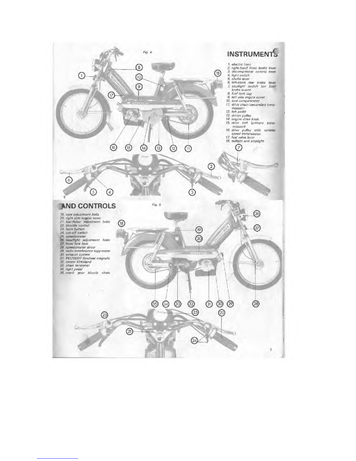
—Put the engine drive knob in the «Bt? position [Fig. 9, page 9)
—Put the fuel valve in the ON position \bike on stand)
—Put the ignition switch \5) on the PUN position
—Get agood hold on the handlebar grips
—Turn the throttle twist grip i3) s//ghtly with your right hand
—Squeeze the choke \2) with your feft hand
—With your right thumb squeeze completely the decompressor
control fever if).
-Starting with the left hand pedal at its top position kick the
pedal down sharply and release the decompressor lever 113
(right thumb) when the left hand crank arm reaches the
bottom.
-Repeat this kicking operation two or three times ft the engine
is cold.
-As soon as the engine engages, use the throttle \3) to give it
some more gas.
-After the engine has run for afew seconds, release the
choke [2).
Stop the rear wheel from spinning simply by squeezing the left
hand rear brake lever [4).
-To take the Moped off its stand, hold the seat firmly and
push forward slowly,
-Briefly :Check to see that your stoplight operates properly
when one or both brake levers are squeezed. Check your
headlight, tail light, and horn.
-5// in the saddle andrto get under way, push off with your
feet and accelerate simultaneously.
b. The second method of starting involves pedaling tire Moped
like abicycle in order to turn the engine over. This method is
especially suited to starts you would make on adown-grade,
-Put the engine drive knob In the <r B»position [Fig. 9, page 9).
-Put the fuel valve in the ON position and sit in the saddle
-Put the ignition switch to its HUN (53 position and engage the
throttle slightly
-Squeeze both Vie choke fever i2), and decompressor control
fever W
-Push off and pedal the Moped
-As soon as the engine is turning, release the decompressor
control lever (7) [right thumb) and open the throttle more
3-After the engine has started and run for afew seconds,
release the choke fever {left hand)
—Note ;In cold weather you can prevent engine stalling by
keeping the choke lever depressed for afew hundred yards of
travel. But do not use the choke lever when you start up a
Moped engine that is already warm.
Important Note on Breaking in Your New Machine :
PBOGFOT's experience has demonstrated that Moped engine
efficiency, power, and durability ere directly tied to the kind of
treatment you give your engine when it is brand new. To break
your engine in properly, ride the Moped at moderate speeds for
its first three hundred miles, Do not race the engine when tt is
new, and be careful you do not overheat it either through long
idling or in hot weather.
SLOWING DOWN AND STOPPING
To slow down and stop in anormal manner, close the throttle
and apply both brakes simultaneously. Whan you have coma to a
full stopj your Moped engine will idle in a"neutral" gear as the
clutch plate automatically disengages.
While your engine is idling with the Moped at a standstill, do not
race or "rev-up" the engine. This action will cause the automatic
clutch to re- engage.
When you are ready to move forward again, simply open the
throttle and accelerate. If you are starting on an up-grade, you
may have to pedal to help your engine get the Moped under way.
For your safety and convenience tv/o devices have been provided
to stop the engine. First, an ignition switch [Fig. 70.5), is located
just ahead of the nght handlebar grrp. Second, the decompressor
control lever, which will cut off engine compresston and stop the
motor, is located just under the right handlebar grip {Fig. 10. tl
PARKING :How to put your Moped on Its stand
fo park your Moped, hold both handlebar and seat. Lower the
center stand with your foot and pull the bike backwards and up
onto the stand.
LOCKING SYSTEM
The PFUGFOT Moped is equipped with afront fork Jock located
on fhe right side of the ''steering rube" or fork [Fig. 11). When
the front wheel is turned to the left, the lock socket will align
with the locking bolt. Turn the key counter-clockwise and push it
down until the bolt engages the lock socket Turn the key back
and remove. To unlock the forks, insert the key, turn it
counter clockwise and pull up until the bolt disengeges.
*5f. 11
11

HOW TO USE YOUR MOPED AS ABICYCLE
^^&^S^^.m*an empr*ft* hYOU may
?7, the Mwrf fhe stopped In order to
nrlf Si ^Centef °fthe C™* *> WThis
°Pfe*°r> mustalway be performed with the engine shot oft If I
exteZeo^ZZT/^ y°U WY0Ur Moped "»**2
extended period of time or especially when gome down astone
EXTENDED STORAGE
tfYM ten to store your Moped for an extended period of time
we recommend you prepare your bike in the Mowing w7y[-
a. Empty the fuel rank
bRun the engine untH the carburetor is empty of fuel
c. Remote the spark plug Y
tf. Put afew drops of oil directly into the cylinder
*' toeZZdT™ °™t¥ ***** in °rdGr to ***** to* oa **
tReplace the spark plug, but do not tighten it
g. Clean and lubricate your Moped as specified in the section
concerning maintenance (p. 13) secuon
*,fhth and fub"CBt*metaifC P*** ms light
Oil coaung waprotect your bike against rust. 9
AFTER STORAGE
gas directly mto the cylinder to remove The oil coating.
\2
CHAIN MAINTENANCE
As we have indicated in the lubrication schedule above, the
secondary transmission drive chain \and the crank gear bicycle
chain] must be lubricated every 600 miles (1000 km). And before
lubrication, both chains must be cleaned of rhe old grease end
dirt which can cause premature wear, It the chains are not
excessively dirty, simply clean them using asmall brvshfa
solvent, and acloth. If a thorough cleaning is called for, remove
both chains and soak them in agood solvent. After you brush
the chains clean, hang them up to dry. After drying, reassemble
them on the Moped before you apply new oil- \With the Moped
on its stand, rotate the rear wheel slowly and let the new oil drip
on both the inside and outside links of the chain. I
DRIVE-CHAIN ADJUSTMENT tSee Fig. 14)
In order to tighten up adrive chain that has more than 112"
{12.5 mm\ slack in it [i.e., movement up and down) :
a. Loosen rear &xfe nuts [31
b. Turn the adjuster nuts of chain xensioners Q) an equal amount
in the rear drop-outs of the frame.
c. Check to see that the rear wheel is aligned in the center of
the chain stays.
The correct chain tension may be gauged by pressing the chain
down at its midpoint Over-ail slackness should not exceed 1/2"
[tZB mm). Always turn the rear wheel of the Moped to make
sure that the tension In rhe chain is consistent. After you are
satisfied with the chain tension, tighten the rear axle nots and
recheck the effectiveness of The rear brake.
Fig- M
14
BICYCLE CHAIN ADJUSTMENT
The chain you use to pedal the Moped is autometically tensioned
by the bicycle chain xensioner {similar to aderaif/eur). No
adjustment is necessary. The PEUGEOT Mopeds have aspring
which automatically keeps aproper tension in the primary
Transmission drive belt No adjustment is necessary,

CLEANING
The quality of the chrome plating and enamel paints used on the
PEUGEOT Mopeds allows for amaintenance program similar to
one used for automobiles. Dirty parts of the Moped should be
cleaned with water and asoft detergent, rinsed thoroughly, and
dried with achamois.
Spots of tar -can be removed with ade tarring solvent or
turpentine. Hub the tar spot with acotton pad or cJoth dipped in
solvent until the tar is gone. Rinse the area immedrateiy
afterwards and wipe dry with asoft cloth.
Your Moped will keep its high lustre if you follow acfeening fob
with the application of ayood pofish Or siticone-base wax. Use
your pofish on both painted and chromed surfaces.
If necessary, restore scratched or grazed enamel surfaces with an
aerosot can of Peugeot spray paint or Peugeot touch-up paint
available through your Peugeot dealer.
important :DO NOT clean your Moped with solvents iike
gasoline, oil, or alkaline washes which always tarnish the lustre of
the enamel. Also, plastic parts are to be washed only with water
or soup and w&ter.
TRA VEL UMITATION OF THE OSCilLA TING ENGINE j
On models equipped with an automatic variable speed transmis-
sion unit, the engine which has been designed to ensure a
constant tension of the drive beir is provided with atravef (imitator
which must be adjusted as fofiows:
-Remove the V-bett from The driven puftcy.
-Screw or unscrew the adjusting nut Aso as to obtain aciea-
ranee J-1/28" 17 mm) between the edge of the air intake sifen
cer and the ft rear suspension arm,
-Re-install the dnvo belt.
OUBLE SHOOTING
L'Mat ot apunctured tire, you may do your own repair by
the instructions below
:
VING THE FRONT WHEEL
zt the speedometer cable from the driver unit by
the cable out.
•t the brake cable by pushing the brake arm
\4, fig. 16) page 16, and unhooking the cebJe stop.
The front axfe nuts 15) end the wheel will drop out of
fork ends.
THE REAR WHEEL
nect the brake cable. py$b the brake arm [t,
forward and unhook the cable stop without
mg it.
loosen wheel nuts (3) and disengage the chain tensioners [2)
Without changing their adjustment
Lift the crankgear "bicycle" chain off without removing the
master link spring clip,
rf, Remove the drive chain by undoing the spring clip on the
master iink.
... Pull rear wheel back until it is free..
REPAIRING THE FLAT
remove the tire from the rim, you should use agood set of tire
First, let ail the air out of your tube and break the "bead"
ond between tire and rim. Then pry the tire up and over the
the tire fevers.
you have patched the tube and checked She tire eating
carefully inside and out for any nails, giass, or damage, inflate
the tube slightly. Then, with one bead of the tire already on the
stuff the tube into the rim well and tire. Use the dull end of
tire fevers to hefp pry the second bead of your tire onto the
the tire to tr& proper pressure end reinstall. Fig. U
J7

ENGINE TROUBLE
If... the engine will not start, or stops completely white you are
driving along, or misfires and skips. ..check first to see if your
fuel rank is empty. If so, put your fuel Una fever in the RESERVE
position {fig, 19). Your reserve supply of gas should take you
about six mites.. .and to the nearest yas station.
ft... your engine suddenly shuts oft while you are driving, then
you way have acddently bumped your ignition switch to the
"OFF" position. Put the ignition switch to "HUN" and restart.
{Afso, if your engine doesn't 'fire' at alt when you try to start it,
check the ignition switch and be sure Af$ in the KRUN »position).
tf... your engine isn't getting the fuei it needs... your fuef Una
may be blocked. Disconnect the fuef pipe from the carburetor
and open the tap to check the gas flow, if needed, cfean both the
tap fitter [Fig. 19) and air holes in the tank cap [Fig. 16).
tf... thejet is clogged <Fig. 20, t\, take it out of the carburetor and
b/ow it out with your tire pump. DO NOT try to dean it with any
mewl wire which coufd affect the output of the jet.
tf. the motor stops when you squeeze one or both brake fevers,
change the Mb of the rear stoplight
If... the spark pfug is dirty or worn, clean or replace it. ft is
always desirable to carry anew spark plug as a spare in the foot
compartment, [Don't forget that it is afragile part and should be
kept in its originat package.) tf the spark pfug gets wet, ignition
cannot occur. Remove the plug, cfe&n <ttrtnd dry ft-
tf... none of the remedies above improve an engine performance
that is beiow par, you should take your Moped to your PEUGEOT
dealer. He has the appropriate equipment and tools, and he is
fully qualified to perform needed repairs and adjustments. Of
course, consult your PEUGEOT dealer immediately should you
experience any important failure regarding the carburetor,
flywheel magneto, clutch, transmission, etc.
WCAL SYSTEM
mtucTRic*
\fOHTS AND IGNiTION SWITCHES
"fectricat system {Fig. 2J) of the PEUGEOT Moped has been
ihisiuned to function in asafe, efficient and completely reiiabte
Miy Alt connections and fines have been shielded from the
tfffrcts of weather and frictions! wear.
The Ireadlight switch <1) is located Just ahead of the left
ft i. uffehar grip. In rhe "L.O. "\0N> position —either forward or
backward -the switch controls the headlight, red tail light, and
Ipmdorneter light. In order to shut the tights off, simply push the
IWttch lever to the intermediate position fabefed "LIGHTS"
\QFF).
Ttw button heated just ahead of the left grip (?) operates the
hunt
TftQ ignition switch \3), heated just ahead of the right throttle
t/itp, controls the flow of electrical current to the engine. You
Imust set this switch in the PUN position in order to start and
ferrate the engine. When the ignition switch is pushed to the
nosition, the engine wilt stop.
right and feft brake levers operate independentfy to activate
rear stopfight
:Electric current is provided by means of affywheef
to iFig. 20.2 -page 18).
HEADL iCH TADJUS7MhHT
In order to ride safety at night, your headlight should be kept in
good adjustment. For night riding, your light must nor be set so
hrgh as to blind other drivers coming towards you. To adjust your
headlight, proceed as follows :
a. Slightly loosen the two headlight ad/ustmenr holts (Fig. 22).
b. Station the bike thirty-three feet from awall.
c. With arider sitting on the Moped, which is off its stand, the
focal point of the Moped headlight beam should appear on
the wail about 1.66 feet [0.50 meter) above the ground. In
order to adjust the t9mp to attain the necessary angle, simply
tip the fight with your /tands. Then lighten the headlight
adjustment bolts.

LIGHTING SPECIFICATIONS
iflefer to your PEUGEOT dealer for all Moped replacement
lightbufbs and parts).
I'nadiigm Ton light
and StaCttthl
103 L2.UI LUXOH ;9V IBW GfXJLCi, dV. 5W bub
BfV«ar BA 15 5,
6V, I0MV Bult»5r-rnw
"-BA 15 S.
noi proviifcit wlh a
-03 12 Si dfrn ditto
103 L2.U3 CEV ;8V 20W Swtod CEV.. BV. 18/HW Bub
MMl Doilbk RbniflnM
Scim Bubo BA 15 D.
ditto
1C3 SP.U2 LUXOR :eV. 19W
KB $—« Beam. ULO, 6V. SA'Bulft
Scwi Bms BA 15 B.
GV. 10W flu .j Screw
P*w BA15.S.
6V. O.SWBJb-Screw
Bom E1Q
1CGSP.U0 dine dine ditto
IB U.U1 ditto UlttO
103 LV6U2 ditto ditto ditto
103 LVS Ul CEV. ev. 20W
Seated Bearts
CEV ISV IB.'SW
MM Onibm PilanwnU
Screw Bum: BA 15 Ddino
REMOVING THE SEALED BEAM AND L/GHT BULBS
Headlight
4Loosen screw at the bottom of the head tamp.
b. Pull the bottom parr of The lens and chromed light cover
away from the base.
c. Disconnect the two electric wires from rhe sealed beam.
d. In order to free the sealed beam from the chrome cover,
remove the clips which fasten the fens to the chrome
frame of the light unit UVoie ;Exercise particular care in ell
these operations..- the light unit is afragile one- If you
experience any problems, consult your PEUGEOT deafer).
TaHUght \Fig. 24)
a. Loosen rhe two tense cover screws and remove (he cover.
b. Push the bulb in slightly and twist it counter-clockwise to
free the pins in the base of bulb from the bulb socket
Speedometer {Fig. 23)
Pull the bulb support down and out of its socket. Unscrew rhe
bulb.
.1
Fig. 23
20
vib^w]
ELECTRICAL WIRING DIAGRAM
BV-30W
to* ccv rttwdbahi
ev '8W
t« LLX0R Hi:.vH*>,|
COLOUR COOE
>,i i/Rf-!
1RJJi 11 RID
2_jyjt 12 >T1:.
3Biuf ZD 13
iBLUt 14 r-i, i!
fi ULlOV. <S3 IS
6VTLIOW —J 16 6IACK
?'ILL OA' BLACK
si [ .r. PIB ilj
qnto 1*
10 BLACK
10 _w—
1
itopttght I
taillfghl bulb
i-ULO' ta**tap unrf ff but>.l.
21

ELECTRICAL WIRING DIAGRAM
Fig. 26
22
Other manuals for 103 LS-U1
3
This manual suits for next models
7
Other PEUGEOT Motorcycle manuals

PEUGEOT
PEUGEOT SPEEDFIGHT 2021 User manual

PEUGEOT
PEUGEOT KISBEE 50 2021 User manual

PEUGEOT
PEUGEOT TWEET 50 2021 User manual

PEUGEOT
PEUGEOT Vivacity 50 CC 2 Stroke Installation guide

PEUGEOT
PEUGEOT 103 LS-U1 User manual

PEUGEOT
PEUGEOT 103 LS-U1 User manual

PEUGEOT
PEUGEOT METROPOLIS ABS 2021 User manual

PEUGEOT
PEUGEOT DJANGO 50 2021 User manual

PEUGEOT
PEUGEOT METROPOLIS 2019 User manual