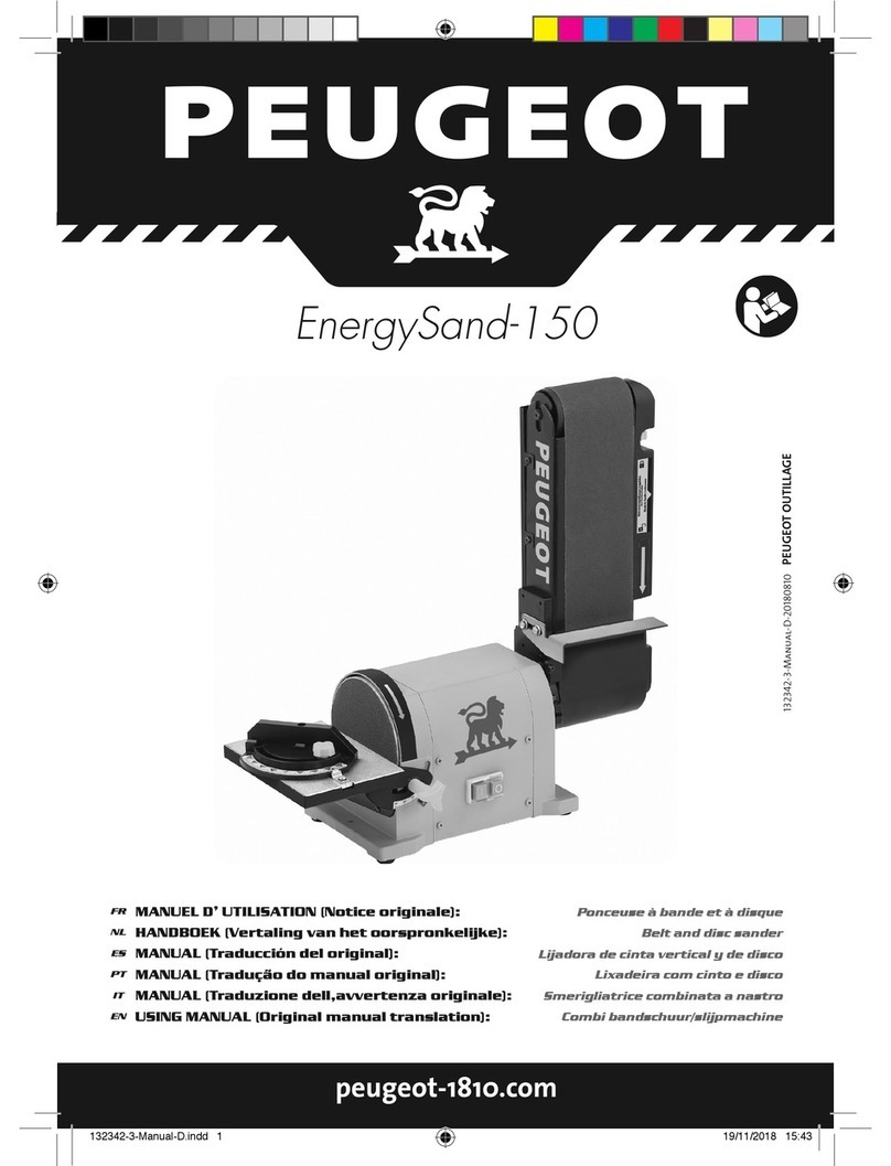
PEUGEOT ENERGYSand-100 User manual

1 1
14. MAINTAIN TOOLS WITH CARE. Keep
cutting tools sharp and clean for better and
safer performance. Follow instructions for
lubricating and changing accessories. Inspect
tool cords periodically and if damaged have
them repaired by an authorised service facility.
Inspect extension cords periodically and
replace if damaged. Keep handles dry, clean
and free from oil and grease.
15. DISCONNECT THE POWER SOURCE.
When not in use you should disconnect tools
from their power source, especially when
changing blades, bits, cutters or other similar
accessories and for servicing.
16. REMOVE ADJUSTING KEYS AND
WRENCHES. Form the habit of checking to
see that keys and adjusting wrenches are
removed from the tool before turning it on.
17. AVOID UNINTENTIONAL STARTING. Ensure
switch is in “off” position when plugging in.
18. USE OUTDOOR EXTENSION LEADS. When
the tool is used outdoors, use only extension
leads intended for outdoor use and so marked.
19. STAY ALERT. Watch what you are doing, use
common sense and do not operate the tool
when you are tired.
20. CHECK DAMAGED PARTS. Before further
use of the tool, it should be carefully checked
to determine that it will operate properly and
perform its intended function. Check the
alignment of moving parts, binding of moving
parts, breakage of parts, mounting and any
other conditions that may affect its operation. A
guard or other part that is damaged should be
properly repaired or replaced by an authorised
service center unless otherwise indicated in
this instruction manual. Do not use the tool if
the switch does not turn it on and off.
21. ACCESSORY WARNING. The use of any
accessory or attachment other than one
recommended in this instruction manual may
present a risk of personal injury.
22. HAVE YOUR TOOL REPAIRED BY A
QUALIFIED PERSON. This electric tool
complies with the relevant safety rules.
Repairs should only be carried out by a
qualied person using original spare parts,
otherwise this may result in considerable
danger to the user.
23. CHECK YOUR MAIN ELECTRICAL SUPPLY,
Short voltage drops can appear when
starting the equipment. This can effect other
equipment that may be on use, such as the
blinking of a lamp. If the mains impendence is
Zmax < 0.34 OHM such disturbances should
not occur.
24. ATTACH THE MACHINE TO A WORK
SURFACE/BENCH. Ensure that the machine
is securely xed to a bench or other work
surface wherever possible.
General Safety Rules
Read all these instructions before
attempting to operate your product. Save
these instructions for future reference.
1. KEEP WORK AREA CLEAR. Cluttered work
areas and benches invite injuries. Keep the
oor area around you level, well maintained
and free from loose materials, such as chips
and excess stock.
2. CONSIDER WORK AREA ENVIRONMENT.
Do not expose tools to rain. Do not use tools in
damp or wet locations. Keep work area well lit.
Do not use tools in the presence of ammable
liquids or gases.
3. GUARD AGAINST ELECTRIC SHOCK.
Avoid body contact with earthed or grounded
surfaces.
4. KEEP OTHER PEOPLE AWAY. Do not let
others, especially children, not involved in the
work touch the tool or the extension lead and
keep them away from the work area.
5. STORE IDLE TOOLS. When not in use, tools
should be stored in a secure and dry location
that it is safely out of reach from children.
6. DO NOT FORCE THE TOOL. It will do the job
better and safer at the rate for which it was
intended.
7. USE THE RIGHT TOOL. Do not force small
tools to do the job of a heavy duty tool. Do
not use tools for purposes not intended; for
example do not use circular saws to cut tree
limbs or logs.
8. DRESS PROPERLY. Do not wear loose
clothing or jewellery, they can be caught
in moving parts. Non-skid footwear is
recommended when working outdoors. Wear
protective hair covering to contain long hair.
9. USE PROTECTIVE EQUIPMENT. Use safety
glasses. Use face or dust mask if cutting
operations create dust.
10. CONNECT DUST EXTRACTION
EQUIPMENT. If devices are provided for the
connection of dust extraction and collecting
equipment, ensure these are connected and
properly used.
11. DO NOT ABUSE THE CABLE. Never pull the
cable to disconnect it from the socket. Keep
the cord away from heat, oil and sharp edges.
12. SECURE WORK. For safety reasons,
wherever possible use clamps or a vice to
hold the work piece securely. It is safer than
using your hands.
13. DON’T OVERREACH. Keep proper footing
and balance at all time.
WARNING ! When using electric tools basic
safety precautions should always be followed
to reduce the risk of re, electric shock and
personal injury.

2 3
2 3
switch and remove plug from power source
outlet. Replace missing, damaged or failed
parts before resuming operation.
21. NEVER PULL THE POWER CORD out of
the receptacle by pulling on the cord. Keep
cords away from heat, oil and sharp edges.
22. HAVE AN ELECTRICIAN REPLACE
OR REPAIR damaged or worn cords
immediately.
23. NEVER use the belt / disc sander near
ammable liquids, vapors, or gases.
24. KEEP the belt / disc sander with proper
footing on a table to decrease noise and
vibration.
SYMBOLS
V ………....volts A ……..…...........amperes
Hz… ….….hertz W.............................watts
min …........minutes ~…. ....alternating current
h …............hours I ……….................... ON
O ….…......OFF
min-1 …......revolutions per minute
Wear safety goggles
Wear ear protection
Wear a breathing mask
Read the manual
WARNING! To reduce the risk of injury,
user must read instruction manual.
ENVIRONMENTAL PROTECTION
Waste electrical products should not
be disposed of with household waste.
Please recycle where facilities exist.Do
not dispose of electrical appliances as
unsorted municipal waste, use separate
collection facilities. Contact your local
government for information regarding the collection
systems available. If electrical appliances are
disposed of in landlls or dumps, hazardous
substances can leak into the groundwater and get
into the food chain, damaging your health and well-
being. When replacing old appliances with new
once, the retailer is legally obligated to take back
your old appliance for disposal at least for free of
charge. Disposal of discarded material shall be in
accordance with local environmental regulations.
Motor .................................. 450 W, 230V ~ 50Hz
Belt ................................................100 x 914 mm
Disc ..................................................... Ø152 mm
No load speed .................................... 2875 min-1
Work table ...................................... 225 x 149 mm
Net Weight ............................................... 22.5 kg
Table tilt ...................................................00~ 450
Belt tilt ......................................................00~ 900
Belt speed ............................................448 m/min
Belt dust chute ......Ø31.5 mm I.D. x Ø38 mm O.D.
Disc speed ...........................................2875 min-1
Disc dust chute .....Ø31.5 mm I.D. x Ø36 mm O.D.
Additional Safety Rules for
Belt / Disc Sander
1. This sander is designed to sand wood or
wood-like products only. Sanding or grinding
other materials could result in re, injury or
damage to workpiece.
2. USE sander on horizontal surfaces only.
Operating the sander when mounted on non-
horizontal surfaces might result in motor
damage.
3. TO STOP it from tipping over or moving when
in use, the sander must be securely fastened
to a bench top or supporting surface.
4. PLACE the sander so neither the user nor
bystanders are forced to stand in line with
the abrasive belt or disc.
5. MAKE SURE the sanding belt is installed in
the correct direction. See directional arrow
on back of belt.
6. ALWAYS have the tracking adjusted properly
so the belt does not run off the pulleys.
7. DO NOT USE sanding belts or discs that are
damaged, torn or loose. Use only correct
size sanding belt and disc. Narrower belts
uncover parts that could trap ngers.
8. MAKE SURE there are no nails or foreign
objects in the part of the workpiece to be
sanded.
9. ALWAYS HOLD the workpiece rmly when
sanding. Keep hands away from sanding belt
or disc. Sand only one workpiece at a time.
10. ALWAYS SAND ON THE DOWNWARD
SIDE of the sanding disc when using the disc
sander. Sanding on the upward side of the
disc could cause the workpiece to y out of
position, resulting in injury.
11. ALWAYS maintain a minimum clearance
of 1.59 mm or less between the table or
backstop and the sanding belt or disc.
12. DO NOT sand pieces of material that are too
small to be safely supported.
13. KEEP ngers away from where the belt goes
into the dust trap
14. WHEN sanding a large workpiece, provide
additional support at table height.
15. DO NOT sand with the workpiece
unsupported. Support the workpiece with the
backstop or table. Plan your work support.
16. NEVER USE ANOTHER PERSON as
additional support for a workpiece longer or
wider than the table.
17. ALWAYS remove scrap pieces and other
objects from the table, backstop or belt
before turning the sander ON.
18. NEVER perform layout, assembly or set-up
work on the table while the sander is operating.
19. NEVER use solvents to clean plastic parts.
Solvents could dissolve or otherwise damage
the material. Use only a soft damp cloth to
clean plastic parts.
20. SHOULD any part of your sander be missing,
damaged, or fail in any way, or any electrical
components fail to perform properly, shut off
Specications

2 3
2 3
3. Tighten the two screws M4*0.7-12 (2).
DISC TABLE ASSEMBLY INSTALLATION (FIG.
6)
The worktable can be used with either the
sanding disc or the sanding belt. It should
be used to support workpieces in all sanding
operations except inside curve applications.
1. Insert the table support rod (1) into the disc/
belt table assembly (3) as shown. The rod
should be ush with the front of the mounting
bracket.
2. Tighten the hex bolt M8*1.25-12 (4) on the
table bracket making sure the bolt is against
the at side of the rod.
3. Insert the other end of the rod into the sander
base until the table is 1.59 mm from sanding
disc.
4. Tighten the hex bolt M8*1.25-70 (2).
IMPORTANT: Use a combination square to
position mitre gauge perpendicular to face of the
disc. If it is not square loosen mitre gauge knob
and move mitre gauge, slightly, until it is square.
BELT BACKSTOP INSTALLATION (FIG. 7)
The belt backstop prevents the workpiece from
being pulled or dragged beyond the sanding belt
surface. It should always be used to help control
the workpiece.
1. Position belt backstop (1) about 1.59 mm
above sanding table (2).
2. Place a washer 1/4*3/4-1/16 (3) on the hex
bolt 1/4*20UNC-1/2 (4).
3. Insert the bolt through the slotted hole into the
threaded hole in the side of the sanding table (2).
4. Tighten hex bolt (4) securely.
BELT DUST COLLECTOR INSTALLATION (FIG.
8)
1. Attach the belt dust collector (1) to the sanding
belt table as shown.
2. Insert the two screws 10#*24UNC-1/4 (2)
through the two washers 3/16*3/8-0.02, belt
dust collector (1) into the sanding belt table.
3. Tighten the two screws 10#*24UNC-1/4 (2).
HEX WRENCH STORAGE (FIG. 9)
Insert the long end of the hex wrench (1) through
the hole (2) located on the surface of the pulley
cover as shown.
OPEN END WRENCH STORAGE (FIG. 10)
Insert the handle of the wrench (1) into the metal
clip (2) located on the back of sander as shown.
The noise levels of this machine during cutting
are as follows:
Maximum sound pressure level: 75.6 dB (A)
Maximum sound power level: 88.6 dB (A)
Uncertainties equal to 3 dB.
Lift the sander from the carton and place it on your
work bench.
INSTALLATION (FIG. 1, 2, 3)
Know Your Belt / Disc Sander
1. Back stop
2. Tension lever
3. 100 x 914 mm sanding belt
4. Idler drum
5. Belt tracking knob
6. Table stop
7. Mounting hole
8. On/Off switch
9. Disc dust chute
10. Disc/Belt table assembly
11. 152 mm sanding disc
12. Hex wrench storage
13. Disc housing
14. Belt dust chute
15. Wrench
16. Power cord bracket
17. Mounting hole
18. Wrench storage
19. Mitre gauge
20. Bevel scale
21. Table lock knob
22. Table support rod
23. Auxiliary hole for mounting table to belt
SANDING DISC PAPER INSTALLATION
(FIG. 4)
1. Remove and clean any adhesive or material
left on the disc plate (1).
2. Peel the plastic back from Velcro base and
carefully press the velcro pad (2) rmly in
position around the sanding plate (1).
3. Then you can x the sanding paper on the
velcro pad.
ASSEMBLING DISC SANDING DUST CHUTE
(FIG. 5)
1. Position disc dust chute (1) in place as shown.
2. Insert the two screws M4*0.7-12 (2) through
the disc dust chute and disc housing (3).
WARNING! To avoid trapping the workpiece
or ngers between the table and sanding
disc, the table edge should be positioned a
maximum of 1.59 mm from sanding disc plate
as shown in Fig. 6.
WARNING! Noise can be a health hazard. When
the noise level exceeds 80 dB(A), be sure to
wear ear protection.
Assembly
WARNING! For your own safety, never
connect the plug to power source outlet until
all assembly steps are completed and you
have read and understood the safety and
operational instructions.

4 5
4 5
Setting the tool 5. Push the belt by hand and check to see if the
sanding belt tends to run to one side or the
other on the two drums.
6. If the sanding belt runs toward disc, slightly
turn the tracking knob (6) counterclockwise.
7. If the sanding belt runs away from the disc,
slightly turn the tracking knob (6) clockwise.
8. Plug sander into power source and turn the
switch ON and OFF quickly, and check to
see if the sanding belt moves to either side.
Re-adjust and ne tune tracking knob if
necessary.
9. When proper tracking is achieved, replace
dust chute (2).
CHANGING POSITION OF SANDING BELT
TABLE
Sanding table in vertical position (Fig. 15, 16)
NOTE: The sanding table (1) can be used in
either the horizontal or vertical position.
1. To move the sanding table (1), loosen the two
bolts (2) with the supplied wrench (3) from the
slots of the side pulley cover that attach table
to the main body.
2. Move the sanding table (1) to the desired
position.
3. Tighten the two bolts (2).
4. Remove the disc/belt table and rod (3) from
the sanding disc area by removing the hex
bolt near base. (Fig. 16)
5. Place the hex bolt (4) into the threaded hole
near the auxiliary hole.
6. Slide the rod (3) into the auxiliary hole for the
belt table (5) until the table is 1.59 mm from
sanding belt. (Fig. 16)
7. Align at surface onto support rod with hex
bolt (6) on table bracket and tighten the bolt
(6).
LEVELING THE ARM (FIG. 17)
A positive table stop (4) is provided to position
the sanding table level with workbench when the
table is in the horizontal position.
1. Place the sanding table (1) in the horizontal
position.
2. Place a level (2) on the sanding belt and
check to see if the table is level.
3. If an adjustment is necessary, loosen lock
nut (3), and turn the sanding table stop (4)
clockwise to raise, or counterclockwise to
lower, until the sanding table is level.
4. Tighten the lock nut (3).
ADJUSTING DISC TABLE SQUARE WITH
SANDING DISC (FIG. 11)
1. Using a combination square (1), place one
side of the square on the disc table assembly
(2) with the other side against the sanding
disc (3), and check to see if the disc table is
90° to the disc.
2. If the disc table surface is not 90° to the disc,
loosen the table lock knob (4), adjust table
square with disc and tighten the table lock
knob (4).
3. Adjust pointer (5) to the 0° mark on the angle
scale using a screwdriver.
ADJUSTING DISC TABLE ANGLE (FIG. 12)
1. The disc table (1) can be tilted from 0° to 45°
by loosening the table lock knob (2).
2. Tilt the disc table (1) to the desired angle.
3. Tighten table lock knob (2).
REPLACING SANDING BELT AND TRACKING
BELT (FIG. 13, 14)
1. Remove the dust chute (2) from belt by
loosening the two screws (1) (Fig. 13).
2. Slide tension lever (3) to the right to release
tension on the sanding belt (4). (Fig. 14)
3. Remove sanding belt from both sanding
drums (5).
4. Slide new sanding belt over sanding drums.
Making sure the belt arrow located on the
inside of the belt will run in the right direction.
Slide tension lever (3) to the left to apply belt
tension.
WARNING! To avoid injury, always keep the
plug disconnected from the power source
and the switch turned OFF until the sander is
completely assembled and adjusted properly.
WARNING! To avoid trapping the workpiece
or ngers between the table and sanding
disc, the disc table edge should positioned
a maximum of 1.59 mm from sanding disc
plate.
WARNING! After tilting the table, the assembly
must be repositioned on the support rod by
loosening the bolt (3) to a maximum of 1.59
mm distance between the sanding disc and
the edge of the disc table, to avoid trapping
the work or nger between the disc and disc
table.
WARNING! To avoid injury, turn switch OFF
and disconnect the plug from the power
source before removing and installing
sanding belt.
WARNING! To avoid trapping the workpiece
or ngers between the table and sanding
belt, the table edge should be positioned a
maximum of 1.59 mm from sanding belt.

4 5
4 5
Connecting to the Power Supply
Check that the power supply and plug used is
in accordance with your sander. Have a look at
the rating plate of the motor or the rating on the
sander. Any changes should always be carried
out by a qualied electrician.
If not properly earthed this machine can cause an
electrical shock. Be sure that the power supply
outlet is earthed. If there is any doubt, have it
checked by a qualied electrician.
Using an Extension Lead
The use of any extension lead will cause some
loss of power. To keep this to a minimum and to
prevent overheating and motor burn-out, seek
advice from a qualified electrician to determine
the minimum wire size of the extension lead.
The extension lead should be equipped with an
earthed type plug that ts the power supply outlet
at one end, and with an earthed type socket that
ts the plug of this machine at the other end.
NOTE:
We highly recommend that you bolt this sander
securely to a work bench to gain the maximum
stability of your machine. Ensure that the machine
is always xed to a bench whenever possible.
1. It is recommended that you mount your
sander to a workbench or stand in order to
avoid any movement of the sander during
operation.
2. The hardware to mount this sander is NOT
supplied with the sander. The hardware as
shown in Fig. 18 should be used.
WARNING: This machine must be earthed.
WARNING: Avoid contact with the terminals
on the plug when installing (removing)
the plug to (from) the power supply outlet.
Contact will cause a severe electrical shock.
Mounting the tool (Fig. 18)
Operating the Tool
The belt and disc sander is designed to perform
sanding operations on surface, also edge grain.
The sander will also perform freehand forming
and contouring operations. The following
suggestions are recommended for best results
and safest use.
1. Always apply light pressure allowing the
abrasive to remove the material slowly.
2. The workpiece should be moved,
continuously, to avoid burning.
3. Avoid sanding small pieces of wood which will
position the ngers close to the abrasive belt
or disc.
“ON/OFF” SWITCH (FIG. 19)
The I - O push switch (1) is located on the side of
the sander. Press Ito turn the tool ON, and press
Oto turn it OFF.
MITRE GAUGE (FIG. 20)
A mitre gauge (1) is supplied with your sander
and is used with the disc table. The mitre gauge
body can be adjusted from 0° to 45° right or left
for angle or mitre sanding.
1. Install the slide rod into the table slot (2) as
shown.
2. Loosen lock knob (3) and then rotate mitre
gauge body to the desired angle.
3. Tighten lock knob (3).
USING BELT BACKSTOP WITH SANDING
TABLE (FIG. 21)
When using the sanding table in the horizontal
position, to perform surface or edge sanding, the
belt backstop (1) must always be used. Always
hold the workpiece (2) rmly keeping your
ngers always from the sanding belt (3). Always
keep the end of the workpiece against the belt
backstop (1) and move the work evenly across
the sanding belt. Apply only enough pressure to
allow the sanding belt to remove material. Use
extra caution when sanding very thin pieces.
WARNING: To avoid injury, always keep the
plug disconnected from the power source
and switch turned OFF until the sander is
completely assembled and adjusted properly.
WARNING: The bottom edge of the backstop
must be positioned a maximum of 1.59 mm
from the sanding belt to avoid trapping the
workpiece or ngers between the backstop
and sanding belt.
Table of contents
Languages:
Other PEUGEOT Sander manuals

PEUGEOT
PEUGEOT EnergyShine-18VBL User manual

PEUGEOT
PEUGEOT EnergySand-125-OR User manual

PEUGEOT
PEUGEOT EnergySand-200ASP Installation and operating instructions

PEUGEOT
PEUGEOT EnergySand-225 Installation and operating instructions

PEUGEOT
PEUGEOT EnergySand-100B Installation and operating instructions

PEUGEOT
PEUGEOT EnergySand-150 Installation and operating instructions

PEUGEOT
PEUGEOT EnergySand-127 User manual

PEUGEOT
PEUGEOT EnergySand-225 Installation and operating instructions

PEUGEOT
PEUGEOT EnergySand-18VBL Installation and operating instructions

PEUGEOT
PEUGEOT EnergySand-25T User manual