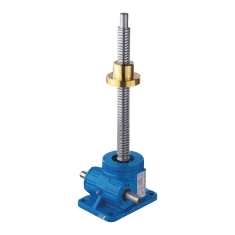
English Wall mounted rack and pinion jack 1.3.102
design changes under reserve page 8
Technical Data
tension
force
pressure force
loading capacity
after Euler II
securing of load rack
length
rack
length
lift per turn
of crank
effort on
crank weight
Type
[kN] [kN] ABC [mm] [mm] [mm] [daN] [kg]
030052000 2,5 2,5 X 740 550 11 11 9
030052001 2,5 2,5 X 765 600 76 22 10
030053001*) 3,0 3,0 X 895 600 11 11 12
030053007 5,0 5,0 X 895 700 11 16,5 10
030054003 10 10 X 765 600 3,8 22 11
030055131 15 15 X 1090 800 14 28 11
030055026 15 15 X 1090 800 14 28 11
030056138 30 30 X975 565 8,6 28 19
030056006 30 30 X 975 565 8,6 28 19
030057134 50 50 X 1170 700 4,5 28 28
030057002 50 50 X 1170 700 4,5 28 28
030058009 100 100 X 1240 700 3,2 40 55
1)
Loading capacity
after Euler II, two
ends are flexible
run on bearings
suitable for ambient temperature -10°C +40°C
*) stainless design
Materials: 1.4301 / 1.4104 / 1.4541; CuZn40Al2; CuSn7Zn Pb
Attention: The resistance has to be checked by the operator before use!
Contact with iron may cause extraneous rust.
Securing the load
Awith worm gearing, self-locking
Bspur-gearing with safety spring crank
Cspur-gearing with safety crank
Technical Data for special designs see annexed data sheet
Functional description:
Wall mounted racks and pinion jacks with self-locking worm gearing.
Type 030052000, 030052999, 030053001, 030053007, 030053502, 030053504, 030053999, 030054003,
030054506, 030054508, 030054802, 030054803, 030054804, 030054805, 030054999,
The load is held in every position by a self-locking mechanism.
Wall mounted racks and pinion jacks with self-locking spur gearing.
Type 030052001, 030052991, 030055131, 030055026, 030055502, 030055504, 040006516, 040004236,
030055999, 030056138, 030056006, 030056604, 030056606, 030056608, 040006515, 030056999,
030057134, 030057002, 030057999, 030058009, 030058999
The securing mechanism is a load pressure brake (SIFEKU or SIKU see technical data).
The safe function of the load pressure brake (only design with SIKU) is only guaranteed, with loads higher
approx. 5% up to 10 % of the nominal load!
Mounting Instructions
Mounting:
ATTENTION:
•the winches are operated for mounting in different devices,
•the mounting structure and the connection with the head of the rack must be designed to sustain the max. forces
imposed by the winch!
•pay careful attention that the mounting surface is flat and true!
•it is not allowed to brace the winch!
•only fix the winch by means of good quality screws!
•tighten the screws evenly secure the crews!
•ensure that the crank is free running (crank clearance)!
•only centric forces are allowed to introduce in the rack!
•flank forces or momentum's are not allowed!
•the save working from the complete construction, has to be guaranteed and checked by the deliverer from the
complete construction!


