Pfaff PLUSLINE 2483-3/03-980 Series Guide

296-12-19 275/002
adjustment Manual engl. 05.16
This instruction manual applies to machines
from the serial number 2809 573 and
software version 0307/010 onwards.
ADJUSTMENT MANUAL
2483-3/03-980/..

Reprinting, reproduction and/or translation of PFAFF instruction manuals (including parts
thereof) is only permitted with our prior agreement and citation of the source.
PFAFF Industriesysteme
und Maschinen GmbH
Hans-Geiger-Str. 12 - IG Nord
D-67661 Kaiserslautern

Table of Contents
Contents..................................................................................Page
15 Adjustment ........................................................................................................................... 5
15.01 Notes on adjustment ............................................................................................................. 5
15.02 Tools, gauges and other accessories .................................................................................... 5
15.03 Abbreviations ......................................................................................................................... 5
15.04 Explanation of symbols.......................................................................................................... 5
15.05 Checking and adjustment aid................................................................................................. 6
15.06 Adjusting the basic machine .................................................................................................. 7
15.06.01 Machine drive home position................................................................................................. 7
15.06.02 Pre-calibrating needle height.................................................................................................. 8
15.06.03 Bottom transporter zero position ........................................................................................... 9
15.06.04 Bottom transporter sliding movement ................................................................................. 10
15.06.05 Bottom transporter stroke movement ................................................................................. 11
15.06.06 Bottom transporter height / position in needle plate cutout ................................................ 12
15.06.07 Needle in needle hole centre............................................................................................... 13
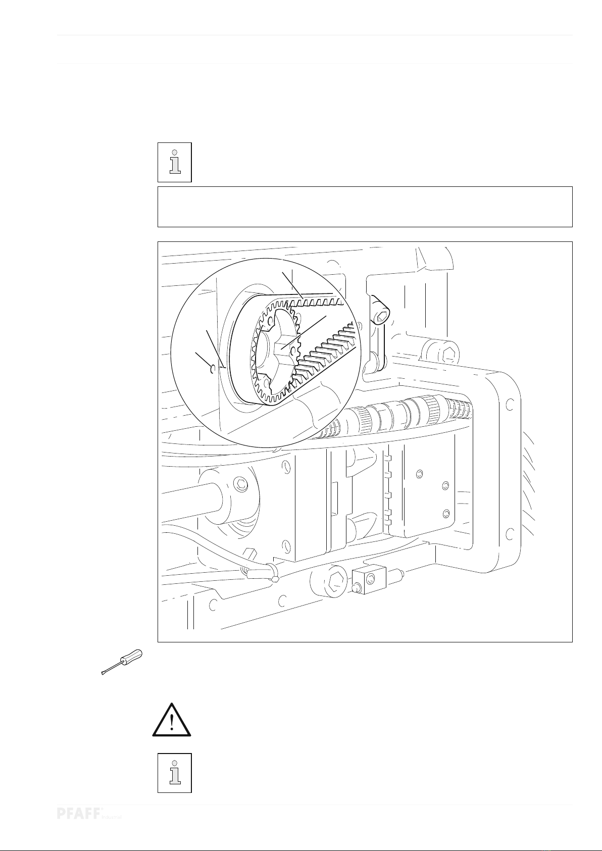
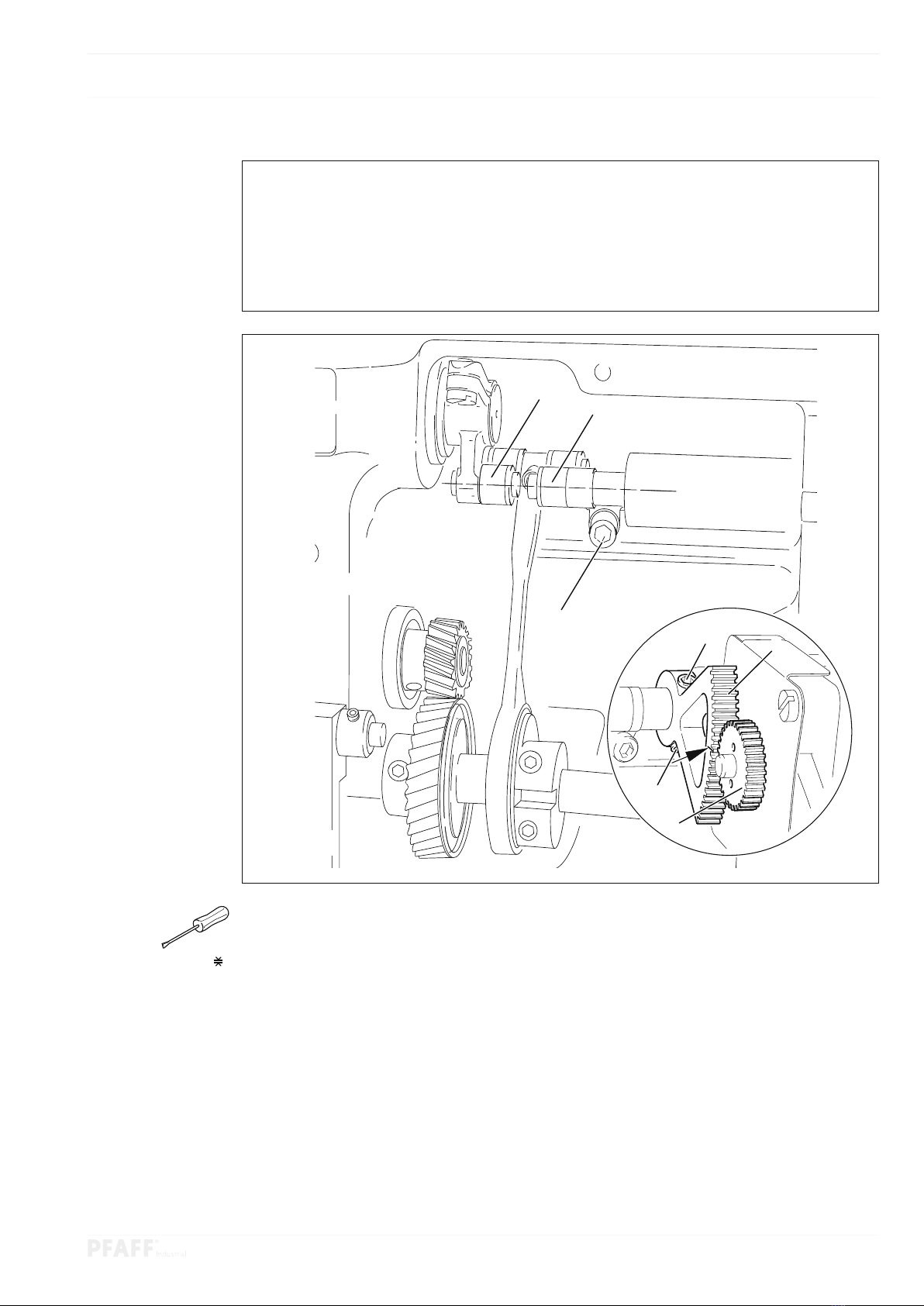
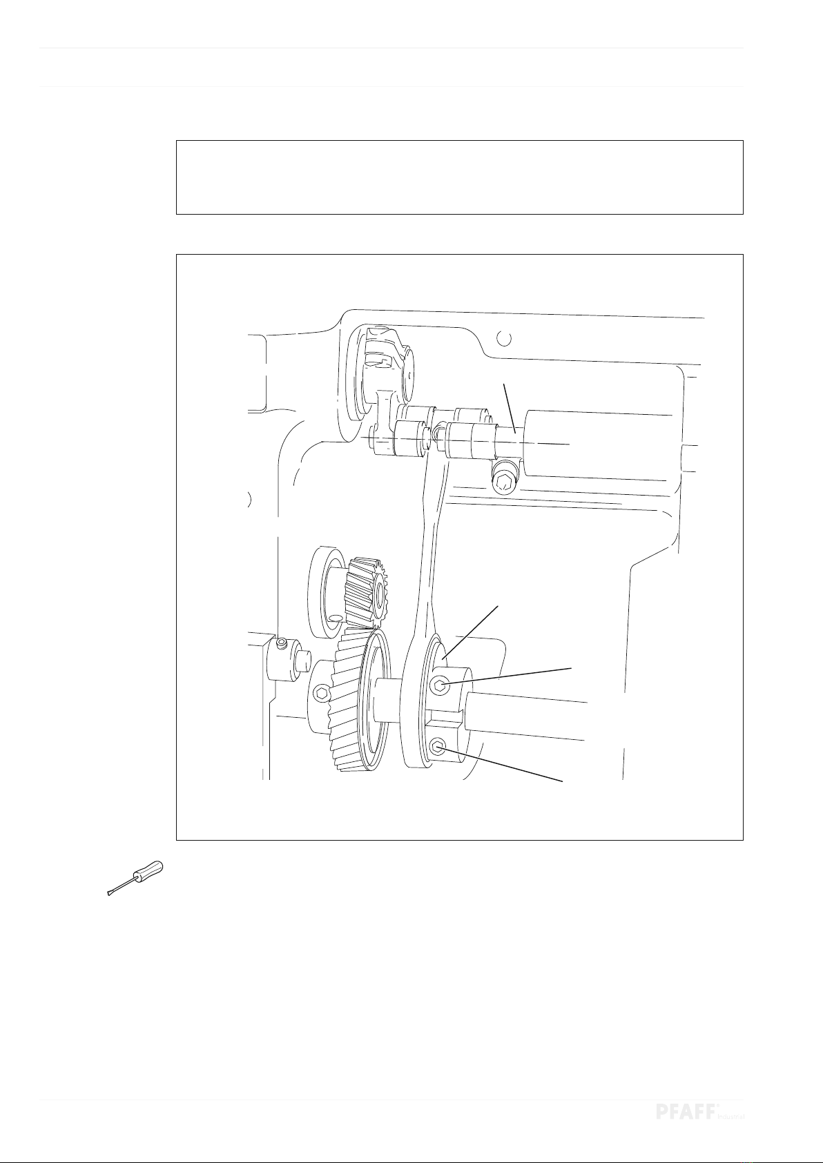
15.06.08 Hook shaft bearing and spur gear clearance........................................................................ 14
15.06.09 Hook lubrication .................................................................................................................. 15
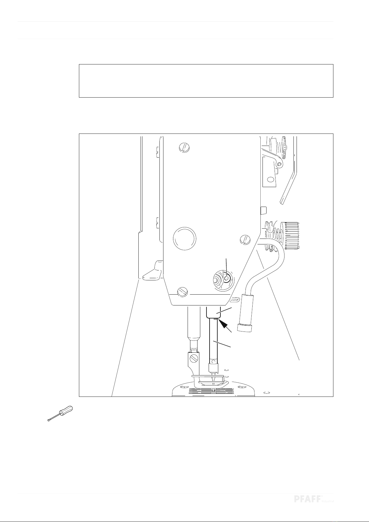
15.06.10 Needle bar rise, hook-to-needle clearance, needle height and bobbin case position finger 16
15.06.11 Thread check spring and slack thread regulator ................................................................... 18
15.06.12 Passage under sewing foot.................................................................................................. 19
15.06.13 Adjusting feed regulator zero position ................................................................................. 20
15.06.14 Stitch length adjustment forwards and backwards.............................................................. 21
15.06.15 Bobbin winder...................................................................................................................... 22
15.06.16 Mechanical stitch length limitation....................................................................................... 23
15.06.17 Sewing foot pressure........................................................................................................... 24
15.07 Adjusting thread trimmer -900/24........................................................................................ 25
15.07.01 Pre-calibrating solenoid setting / control cam ...................................................................... 25
15.07.02 Aligning thread catcher laterally ........................................................................................... 26
15.07.03 Knife position ....................................................................................................................... 27
15.07.04 Front turning point of thread catcher.................................................................................... 28
15.07.05 Manual cutting control ......................................................................................................... 29
15.07.06 Needle thread tension release............................................................................................. 30
15.07.07 Re-calibrating control cam.................................................................................................... 31
15.08 Aligning transmitted light transmitter................................................................................... 32
15.09 Adjusting transmitted light sensors ..................................................................................... 33
15.10 Functional check of bobbin thread monitor .......................................................................... 34

Table of Contents
Contents..................................................................................Page
15.11 Parameter settings............................................................................................................... 35
15.11.01 Overview of parameter functions ........................................................................................ 35
15.11.02 Example of a parameter entry ............................................................................................. 36
15.11.03 Selecting user level.............................................................................................................. 37
15.11.04 List of parameters................................................................................................................ 38
15.12 Error messages and description .......................................................................................... 44
15.13 Sewing motor errors ............................................................................................................ 45
15.14 Service menu....................................................................................................................... 46
15.15 Internet update of machine software................................................................................... 48
16 Circuit Diagrams ................................................................................................................ 49
16.01 Block diagram of PFAFF 2483 with control unit P322 ED .................................................... 49
16.02 Circuit diagrams ................................................................................................................... 50
16.03 Plug connections ................................................................................................................. 55

Adjustment
5
15 Adjustment
Observe and comply with all instructions in the operating manual’s chapter 1
Safety! In particular make sure that all safety covers are installed again correct-
ly after making adjustments, see chapter 1.06 Operating manual hazard infor-
mation!
Unless otherwise stated, the machine must be disconnected from the power
supply before all adjustment work!
Risk of injury due to accidental machine start-up!
No screw clamp may be fastened to the needle bar with the PFAFF
2483-980/33!
This may damage the special needle bar coating.
15.01 Notes on adjustment
All adjustments in this manual are based on a fully assembled machine and may only be car-
ried out by technical staff trained for this purpose. Machine covers, which have to be re-
moved and replaced to carry out checks and adjustments, are not mentioned in the text. The
order of the following chapters corresponds to the most logical work sequence for machines
that have to be completely adjusted. Both the preceding and following chapters must be ob-
served if only specific individual work steps are carried out. Screws and nuts indicated in
brackets ( ) are fastenings for machine parts, which must be loosened before any adjustment
and tightened again afterwards.
15.02 Tools, gauges and other accessories
O1set of screwdrivers with knife widths of 2to 10 mm
O1set of wrenches with jaw widths from 7to 14 mm
O1set of Allen keys of 1.5to 6mm
O1feed dog setting gauge (order no. 61-111 639-71)
O1setting gauge (order no. 61-111 639-73)
O1adjustment pin (5mm diameter), order no. 13-033 346-05
O1metal ruler (order no. 08-880 218-00)
OThread and testing material
15.03 Abbreviations
t.d.c. = top dead centre
b.d.c. = bottom dead centre
15.04 Explanation of symbols
Activities to be performed or important information in this adjustment manual are empha-
sised by symbols. The symbols used have the following meaning:
Note, information
Maintenance, repairs, adjustment, service work
(only to be carried out by technical staff)

Adjustment
6
15.05 Checking and adjustment aid
The adjustment pin 1(order no. 13-033 346-05) and the adjustment gauge 3
(order no. 61-111 639-73) if necessary can be used to fix the required positions
during the adjustment.
Needle bar positioned 1.8 mm after b.d.c.
OTurn the handwheel until the needle bar is approximately in the required position.
OPush the adjustment pin 1 into the hole.
OMove the handwheel gently back and forwards until the adjustment pin 1 engages
in the crank 2.
Needle bar positioned 0.6 mm after b.d.c.
OMove the needle bar approximately into the required position.
OFit the adjustment gauge 3 to the studs 4 and 5 ensuring the right side (for a 30 mm
or 36 mm needle bar stroke).
Fig. 15 - 01
1
2
4
5
3

Adjustment
7
15.06 Adjusting the basic machine
15.06.01 Machine drive home position
This setting is only required if the toothed belt 2has been dismantled.
Rule
The markings 3 and 4 should be aligned if the needle bar is positioned 0.6 mm after b.d.c.
OMove the needle bar to 0.6mm after b.d.c.
OTurn the toothed belt wheel 1according to the rule and slide on the toothed belt 2.
Make sure that the shaft flange, shock absorber and motor flange are in the
right position when installing the motor!
The second toothed belt wheel screw 1is a balance cup screw
Fig. 15 - 02
3
41
2

Adjustment
8
15.06.02 Pre-calibrating needle height
Rule
The marking on the needle bar 1 should be flush with the lower edge of the needle bar
frame 3 when the needle bar is positioned 1.8 mm after b.d.c.
Fig. 15 - 03
OMove the needle bar to 1.8mm after b.d.c. and fix with the adjustment pin, see chapter
15.05 Checking and adjustment aid.
OAdjust the needle bar 1( screw 2) without twisting according to the rule.
2
1
3

Adjustment
9
15.06.03 Bottom transporter zero position
Rule
At stitch length setting “0”
1. The marking on the toothed segment 1 should be in the centre of the shaft of the gear
wheel 3,
2. The cranks 4 and 6 should be aligned and the bottom transporter should not move
when turning the handwheel.
Fig. 15 - 04
OSwitch the machine on.
OSet the stitch length to “0” using the control panel and turn the handwheel until the feed
regulator motor responds.
OMake sure that parameter 834 is set to “0”, see chapter 15.11 Parameter settings.
OAdjust the toothed segment 1( screws 2) without the gear wheel 3according to rule 1.
OTurn the crank 4( screws 5) according to rule 2.
OSwitch the machine off.
6
5
4
1
2
2
3

Adjustment
10
15.06.04 Bottom transporter sliding movement
Rule
When the needle bar is positioned 0.6 mm after t.d.c., the bottom transporter should not
move when the shaft 3 is rotated back and forth.
Fig. 15 - 05
OMove the needle bar to a position 0.6mm after t.d.c.
OTurn the eccentric 1( screws 2), without moving it sideways according to the rule.
3
1
2
2

Adjustment
11
15.06.05 Bottom transporter stroke movement
Rule
When the needle bar is positioned 0.6 mm after t.d.c. and with stitch length regulation “0”
1. the bottom transporter should be in its upper turning point and
2. the control cam 3 should abut the feed lifting eccentric 1.
OSwitch the machine on.
OSet the stitch length to “0” and move the needle bar to a position 0.6mm after t.d.c.
OTurn the handwheel until the feed regulator motor responds.
OTurn the eccentric 1( screws 2) according to rule 1.
OAdjust the control cam 3( screws 4) according to rule 2 and switch off the machine.
Fig. 15 - 06
1
2
4
3

Adjustment
12
15.06.06 Bottom transporter height / position in needle plate cutout
Rule
In its upper turning point and with stitch length regulation “0” the bottom transporter 1 should
1. be in the centre of the needle plate cutout looking from the side and in the feeding di-
rection and
2. abut the feed dog setting gauge 2 along its entire length.
6
7
3
5
4
Fig. 15 - 07
OTurn on machine and set the stitch length to “0”.
OTurn the handwheel until the feed regulator motor responds.
OMove the bottom transporter 1 to its upper turning point.
ORaise the sewing foot, move the feed dog setting gauge 2 over the needle plate cut-
out with the arrow in the sewing direction and the front edge flush with the needle plate
edge and lower the sewing foot.
OAdjust the bottom transporter carrier 3 ( screw 4 ) according to rule 1.
OLoosen the screws 5and 6
OAdjust the bottom transporter carrier 3 and eccentric 7 according to rule 2.
OTighten the screws 5and 6
OSwitch the machine off.
2
1

Adjustment
13
15.06.07 Needle in needle hole centre
Rule
The needle should pierce the centre of the needle hole exactly.
1
4
OSwitch the machine on.
OSet the stitch length to “0” using the control panel and turn the handwheel until the feed
regulator motor responds.
OInsert the needle into the needle hole by turning the handwheel.
OLoosen the screws 1,2 and 3
OAdjust the needle bar frame 4 according to the rule.
OTighten the screw 2and gently tighten the screw 3.
OUse the screw 1to pull the internal guide pin up to the eye of the needle bar frame 4and
tighten it.
OTurn the handwheel a few turns so that the needle bar frame 4is not under tension.
OTighten the screw 3.
OSwitch the machine off.
Fig. 15 - 08
2
3

Adjustment
14
15.06.08 Hook shaft bearing and spur gear clearance
Rule
1. The front edge of the hook shaft 5 should be 14.5 mm away from the needle midpoint;
the groove in the hook shaft bearing 1 (see arrow) should be parallel to the bed plate
and point away from the sewing direction.
2. There should be minimal yet noticeable play between the plastic pinion 3and the steel
wheel 4. This play should be approximately the same for a 360° turn.
3. The steel wheel 4 should align with the plastic pinion 3.
3
Fig. 15 - 09
OAlign the hook shaft bearing 1( screw 2) according to rule 1.
OSet the steel wheel 4with the eccentric bush of the hook shaft bearing 1according to
rule 2and tighten the screw 2.
OAdjust the plastic pinion 3( screws 6) according to rule 3 and tighten the screws 6.
4
2
14.5 mm
6
1

Adjustment
15
15.06.09 Hook lubrication
Rule
1. The centrifugal disc 1 should be 1.5 mm in front of the oil distributor ring 3.
2. A light oil strip should appear on a paper strip held over the needle plate cutout after ap-
proximately 10 seconds when the machine is running at full speed.
The setting is only required if the wick is replaced.
Make sure that the new wick is impregnated with oil when replacing the wick.
OAdjust the centrifugal disc 1( screw 2) according to rule 1.
OCheck rule 2 and adjust the centrifugal disc 1if necessary.
Fig. 15 - 10
1.5 mm
2
1
3

Adjustment
16
15.06.10 Needle bar rise, hook-to-needle clearance, needle height and bobbin case
position finger
Rule
When the needle bar is positioned 1.8 mm after b.d.c.,
1. The tip of the hook 6 should be at the needle midpoint and be a distance of 0.05 mm -
0.1 mm from the fillet of the needle and
2. The upper edge of the eye of the needle should be 0.8 mm under the tip of the hook.
3. There should be a clearance of 0.5 mm between the lug of the bobbin case position
finger 4and the base of the stop groove.
OSwitch the machine on.
OSet the stitch length to “0” using the control panel and turn the handwheel until the feed
regulator motor responds.
OSwitch the machine off.
Fig. 15 - 11
0.05 - 0.1 mm
6
10.5 mm
4
2
3
0.8 mm
5
4

Adjustment
17
OUse the adjustment pin to move the needle bar to 1.8mm after b.d.c.
OAdjust the hook according to rule 1
OTighten the screws 1.
OAdjust the needle bar 2( screw 3), without twisting according to rule 2.
OAlign the bobbin case position finger 4( screw 5) according to rule 3.

Adjustment
18
15.06.11 Thread check spring and slack thread regulator
Rule
1. The movement of the thread check spring should be finished when the needle point
punctures the material ( spring deflection: approx. 7 mm).
2. The thread check spring should have moved approx. 1 mm when forming the maxi-
mum thread loop while passing the thread around the hook.
OTurn the thread tension 1( screw 2) according to rule 1.
OAdjust the slack thread regulator 3( screws 4) according to rule 2.
It may be necessary to deviate from the specified spring deflection for reasons
relating to the sewing technology.
Adjust the slack thread regulator 3(screw 4) by “ + ” (= more thread) or
“ - ” (= less thread).
Fig. 15 - 12
7 mm
4
3
-
1
+
2

Adjustment
19
15.06.12 Passage under sewing foot
Rule
1. When the automatic presser foot lift is activated, the clearance between the sewing
foot and needle plate should be should be 7mm.
2. When the hand lever is raised, the clearance between the sewing foot and needle plate
should be should be 5 mm.
Fig. 15 - 13
2
1
7 mm
OAdjust the solenoid 1( screw 2) according to rule 1.
ORaise the hand lever and place the adjustment gauge 3(order no. 61-111 639-73) under
the sewing foot according to rule 2.
OMove the presser bar lifting lever 4so that it touches the lift piece 5.
Make sure that the needle is positioned in the middle of the needle foot.
5 mm
3
4
5

Adjustment
20
15.06.13 Adjusting feed regulator zero position
Rule
The needle should always puncture the material at the same position at maximum speed
(4500 min-1) with stitch length regulation “0”.
Fig. 15 - 14
OUnthread the machine.
OSwitch the machine on.
OPlace the workpiece under the sewing foot.
OSew with the machine at max. speed and check the rule.
(Workpiece must not move.)
OChange the value for parameter 834 within the permissible values according to the rule.
The permissible values for parameter 834 are “-1”, “0” or “1”.
If the feed regulator zero position cannot be set by selecting the permissi-
ble values, the mechanical setting must be checked or corrected, see chapter
15.06.03 Bottom transporter zero position.
The zero position of the feed regulator is always identifiable in a range of 3val-
ues. The middle value must be selected when making the adjustment.
OSwitch the machine off.
Further information about selecting and changing parameters and explanations
(functions) about the individual parameters can be found in chapter 15.11 Pa-
rameter settings.
Table of contents
Other Pfaff Sewing Machine manuals

Pfaff
Pfaff 918 User manual

Pfaff
Pfaff tipmatic 1119 User manual

Pfaff
Pfaff POWERLINE 2571 ME PLUS User manual

Pfaff
Pfaff Creative Performance User manual

Pfaff
Pfaff tiptronic 2040 User manual

Pfaff
Pfaff 918 User manual

Pfaff
Pfaff COVERLOCK 4.0 - User manual

Pfaff
Pfaff 3588-04/020 User manual

Pfaff
Pfaff coverlock 4772 User manual

Pfaff
Pfaff Automatic 260 User manual

Pfaff
Pfaff CREATIVE 2170 SEWING User manual

Pfaff
Pfaff ClassicStyle 1525 User manual

Pfaff
Pfaff Punching Machine Hobby 350p User manual

Pfaff
Pfaff powerLine 2595 Manual

Pfaff
Pfaff Powerline 2545 Guide

Pfaff
Pfaff 3519-5/01 User manual

Pfaff
Pfaff 73 User manual

Pfaff
Pfaff CREATIVE 2124 User manual

Pfaff
Pfaff 1213 User manual

Pfaff
Pfaff 1243 Guide