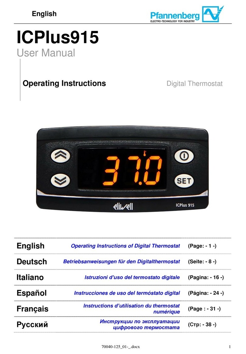
Pfannenberg ICPlus902 User manual

English
70040-089_01-A.docx
1
ICPlus902–ICPlus902/A
User Manual
Operating Instructions Digital Thermostat
English
Operating Instructions of Digital Thermostat
(Page: - 1 -)
Deutsch
Betriebsanweisungen für den Digitalthermostat
(Seite: - 7 -)
Operating
Instructions of
Digital
Thermostat
(Page: - 3 -)
Italiano
Istruzioni d’uso del termostato digitale
(Pagina: - 13 -)
Operating
Instructions of
Digital
Thermostat
(Page: - 3 -)
Español
Instrucciones de uso del termóstato digital
(Página: - 19 -)
Operating
Instructions of
Digital
Thermostat
(Page: - 3 -)
Français
Instructions d’utilisation du thermostat
numérique
(Page : - 25 -)
Operating
Instructions of
Digital
Thermostat
(Page: - 3 -)
Русский
Инструкции по эксплуатации
цифрового термостата
(Стр: - 31 -)
Operating
Instructions of
Digital
Thermostat
(Page: - 3 -)

English
70040-089_01-A.docx
2
Index
1. MAIN VIEW .................................................................................................................................................................3
2. KEYS..............................................................................................................................................................................3
3. PARAMETERS.............................................................................................................................................................4
4. THERMOSTAT MENUS.............................................................................................................................................4
4.1. PROGRAMMING MENU FOLDERS TREE ...................................................................................................................4
4.2. STATUS /SETPOINT MENU ......................................................................................................................................5
5. ERRORS TABLE..........................................................................................................................................................5
6. MAX TEMPERATURE ALARM (ONLY FOR RACK WITH INSTALLED OPTION) .....................................5
7. COOLING .....................................................................................................................................................................6
7.1. COOLING WITH FIXED SETPOINT ............................................................................................................................6

English
70040-089_01-A.docx
3
1. Main view
In main view, the target display shows the value measured by the thermoregulation probe.
Following table explains the meaning associated to LEDs.
Icon
Description
ON
Alarm
ON for an active alarm
°C
With temperature value displayed
Relay of
compressor
Compressor is active
2. Keys
key
Description
press and release
UP
Scroll menu items
Increases values
DOWN
Scroll menu items
Decrease values
STAND-BY (ESC)
Returns to the previous menu level
Confirms parameter value
SET (ENTER)
Displays alarms (if active)
Opens Machine Status menu
Confirm commands

English
70040-089_01-A.docx
4
3. Parameters
EB/RACK Water+Glycol
EB/RACK OIL
To enter
Main
Folder.
Sub-folder
PARAMETER
DESCRIPTION
LEVEL
U.M.
RANGE MIN - MAX
DEFAULT
RANGE MIN - MAX
DEFAULT
Press “set”
button
SEt
-
SP1
SET-POINT for Compressor
-
°C
10…35
16,5
20…35
24,5
4. Thermostat Menus
4.1. Programming Menu Folders tree

English
70040-089_01-A.docx
5
4.2. Status / Setpoint menu
(SEt folder)
Status menu
In main view, press the set key to access
the Status / Setpoint menu.
folder “SEt” will appears
Press set key again to view the value of
selected parameter. To modify this value
Press the "up" and "down" keys. Press the
set key once you have entered the required
value.* Press the esc key to exit this display
and go back to the previous level.
*N.B. pressing the set key will confirm the value entered;
Pressing the esc key will take you back to the previous
level without saving the value entered.
5. Errors table
Label
Description
Reset
Stops
Type of
Error
Comp.
Fan
Pump
E1
Water Temperature Probe
Fault
Automatic (after replacing/repairing of the
probe)
OFF
OFF
-
Alarm
AH1
Alarm for HIGH
Water Temperature Probe
temperature
AUTO (after temperature drops)
-
-
-
Warning
6. Max Temperature Alarm (only for RACK with installed
option)
The regulator gets the temperature measure from the thermoregulation probe; the setpoint of Max temperature Alarm is
40°C for Rack units.

English
70040-089_01-A.docx
6
7. Cooling
7.1. Cooling with Fixed Setpoint
The regulator gets the temperature measure from the thermoregulation probe; the setpoint is 16,5°C + 3°C for
Water+Glycol units and 24,5°C + 3°C for OIL units.
Control action is proportional to the error and it reaches saturation (100%) when the temperature is greater than the setpoint
plus the “Hysteresys” = 3°C.
Compressor Setpoint Settings
Type
Parameter
Factory Setting [°C]
Range of Setting [°C]
EB/RACK Water+Glycol
SEt
16,5
10 - 35
EB/RACK Oil
SEt
24,5
20 - 35
All EB/RACK
WS
SEt + "Df1"/2
11,5 - 35
Df1
3
3

Deutsch
70040-089_01-A.docx
7
ICPlus902–ICPlus902/A
Betriebshandbuch
Betriebsanweisungen Digitalthermostat

Deutsch
70040-089_01-A.docx
8
Inhaltsverzeichnis
1. HAUPTBILDSCHIRMSEITE.....................................................................................................................................9
2. TASTEN.........................................................................................................................................................................9
3. PARAMETER.............................................................................................................................................................10
4. THERMOSTATMENÜ..............................................................................................................................................10
4.1. STRUKTUR DER DIRECTORIES DES PROGRAMMIER-MENÜS..................................................................................10
4.2. STATUS-/EINSTELL-MENÜ ...................................................................................................................................11
5. FEHLERTABELLE ...................................................................................................................................................11
6. ALARM HÖCHSTTEMPERATUR (NUR FÜR DIE MODELLE RACK MIT EINGEBAUTER OPTION)..11
7. KÜHLEN .....................................................................................................................................................................12
7.1. KÜHLEN MIT FESTEM SET-POINT..........................................................................................................................12

Deutsch
70040-089_01-A.docx
9
1. Hauptbildschirmseite
Auf der Hauptbildschirmseite wird der von der Wärmeregulierungssonde erfasste Wert angezeigt.
Aus der nachstehenden Tabelle ist die Bedeutung der einzelnen LEDs zu ersehen.
Symb
ol
Beschreibung
eingeschaltet (ON)
Alarm
ON –ein Alarm aktiviert
°C
Mit Anzeige des Temperaturwertes
Kompressor-
Relais
Der Kompressor ist aktiviert
2. Tasten
Taste
Beschreibung
Drücken und loslassen, um:
UP
Blättert in den Menüoptionen
Erhöht die Werte
DOWN
Blättert in den Menüoptionen
Verringert die Werte
STAND-BY (ESC)
Eine Ebene höher als aktuelles Menü
Parameterwert übernehmen
SET (ENTER)
Anzeige von Alarmen (sofern vorhanden)
Zugriff auf Menü „Maschinenstatus“
Bestätigung der Befehle

Deutsch
70040-089_01-A.docx
10
3. Parameter
EB/RACK Wasser + Glykol
EB/RACK ÖL
Zugriff auf
Hauptdir
ectory.
Subdirectory
PARAMETER
BESCHREIBUNG
EBENE
M.E.
INTERVALL MIN - MAX
DEFAULT-WERT
INTERVALL MIN - MAX
DEFAULT-WERT
Taste “set”
drücken
SEt
-
SP1
SET-POINT für Kompressor
-
°C
10…35
16,5
20…35
24,5
4. Thermostatmenü
4.1. Struktur der Directories des Programmier-Menüs
Legende:
Press and release
(single press)
Drücken und wieder
loslassen
(nur einmal drücken)
SEt value
Set-Wert
Change SEt value
SEt-Wert ändern
Pb1 value
Pb1-Wert

Deutsch
70040-089_01-A.docx
11
4.2. Status-/Einstell-Menü
(Directory SEt)
Status-Menü
Auf der Hauptbildschirmseite die Taste „Set“
für den Zugriff auf das Status-/Einstell-Menü
drücken.
Die Directory “SEt” erscheint
Erneut die Taste „Set“ zur Anzeige des
Wertes des gewählten Parameters drücken.
Um diesen Wert zu ändern, die Pfeile „nach
oben“ bzw. „nach unten“ drücken. Nach
Eingabe des geforderten Wertes* die Taste
„Set“ einmal drücken. Zum Verlassen dieser
Seite und Rückkehr zur vorhergehenden
Ebene „Esc“ drücken.
*Zur Beachtung: Durch Drücken der Taste „Set“ wird der
eingegebene Wert bestätigt; durch Drücken der Taste
„Esc“ erfolgt die Rückkehr auf die vorhergehende Ebene
ohne Speicherung des eingegebenen Wertes.
5. Fehlertabelle
Angabe
Beschreibung
Reset
Stillstände
Art des
Fehlers
Kompr
essor
Lüfter
Pump
e
E1
Störung
Wassertemperatursonde
Automatisch (nach Ersetzen/Reparatur der
Sonde)
OFF
OFF
-
Alarm
AH1
Hoch-alarm Wert
AUTOMATISCH (nach Absenken der
Temperatur)
-
-
-
Warnung
6. Alarm Höchsttemperatur (nur für die Modelle RACK mit
eingebauter Option)
Die Wärmeregulierungssonde erfasst den Temperaturwert und meldet ihn der Einstellvorrichtung; für die Einheiten Rack
ist der Set-Point für den Alarm Höchsttemperatur 40 °C.

Deutsch
70040-089_01-A.docx
12
7. Kühlen
7.1. Kühlen mit festem Set-Point
Die Wärmeregulierungssonde erfasst den Temperaturwert und meldet ihn der Einstellvorrichtung; der Set-Point ist
16,5Errore. Nome della proprietà non specificato. °C + 3 °C für die Einheiten mit einer Wasser-Glykol-Mischung und
24,5Errore. Nome della proprietà non specificato. °C + 3 °C für die Einheiten mit Öl.
Die Kontrolle ist proportional zum Fehler; die Sättigung (100%) ist erreicht, wenn die Temperatur über dem Set-Point liegt,
zuzüglich des Parameters „Hysterese“ = 3 °C.
Set-Point-Einstellungen des Kompressors
Typ
Parameter
werkseitige Einstellung
[°C]
Einstellungsintervall
[°C]
EB/RACK Wasser + Glykol
SEt
16,5
10 - 35
EB/RACK Öl
SEt
24,5
20 - 35
Alle Modelle EB/RACK
WS
SEt + “Df1”/2
11,5 - 35
Df1
3
3
Legend
Legende
Chiller
Rückkühler
Tfluid
Flüssigkeitstemperatur
Thermostat set point
Set-Point des Thermostaten
Chiller working set point
Set-Point Rückkühler-Betrieb
hysteresis
Hysterese

Italiano
70040-089_01-A.docx
13
ICPlus902–ICPlus902/A
Manuale d’uso
Istruzioni d’uso Termostato digitale

Italiano
70040-089_01-A.docx
14
Indice
1. SCHERMATA PRINCIPALE...................................................................................................................................15
2. TASTI...........................................................................................................................................................................15
3. PARAMETRI..............................................................................................................................................................16
4. MENU TERMOSTATO.............................................................................................................................................16
4.1. STRUTTURA DELLE CARTELLE DEL MENU DI PROGRAMMAZIONE..........................................................................16
4.2. MENU DI STATO/IMPOSTAZIONE ...........................................................................................................................17
5. TABELLA ERRORI...................................................................................................................................................17
6. ALLARME TEMPERATURA MASSIMA (SOLO PER MODELLI RACK CON OPZIONE INSTALLATA)
17
7. RAFFREDDAMENTO...............................................................................................................................................18
7.1. RAFFREDDAMENTO CON SET-POINT FISSO ............................................................................................................18

Italiano
70040-089_01-A.docx
15
1. Schermata principale
Nella schermata principale, il display mostra il valore rilevato dalla sonda di termoregolazione.
Nella tabella seguente è riportato il significato di ciascun LED.
Simbo
lo
Descrizione
Acceso (ON)
Allarme
ON - un allarme attivo
°C
Con valore di temperatura visualizzato
Relè del
compressore
Il compressore è attivo
2. Tasti
Tasto
Descrizione
Premere e rilasciare per
Aumentare un valore
Passare alla voce successiva
Ridurre un valore
Ritornare alla voce precedente
Uscire senza salvare le nuove impostazioni
Ritornare al livello precedente
Confermare il valore/uscire salvando le nuove
impostazioni
Passare al livello successivo (aprire cartella, sottocartella,
parametro, valore)
Aprire il menu di stato/impostazione

Italiano
70040-089_01-A.docx
16
3. Parametri
EB/RACK Acqua + glicole
EB/RACK OLIO
Per
accedere
Cartella
principale.
Sottocartella
PARAMETRO
DESCRIZIONE
LIVELL
O
U.M.
INTERVALLO MIN - MAX
VALORE DI DEFAULT
INTERVALLO MIN - MAX
VALORE DI DEFAULT
Premere il
pulsante “set”
SEt
-
Sp1
SET-POINT per compressore
-
°C
10…35
16,5
20…35
24,5
4. Menu termostato
4.1. Struttura delle cartelle del menu di programmazione
Legenda:
Press and release
(single press)
Premere e rilasciare
(premere una sola volta)
SEt value
Valore SEt
Change SEt value
Modificare il valore SEt
Pb1 value
Valore Pb1

Italiano
70040-089_01-A.docx
17
4.2. Menu di stato/impostazione
(Cartella SEt)
Menu di stato
Nella schermata principale, premere il tasto
“set” per accedere al menu di
stato/impostazione.
Appare la cartella “SEt”
Premere nuovamente il tasto “set” per
visualizzare il valore del parametro
selezionato. Per modificare questo valore
premere le frecce “su” e “giù”. Premere il
tasto “set” una volta immesso il valore
richiesto.* Premere il tasto “esc” per uscire
da questa schermata e ritornare al livello
precedente.
*N.B. premendo il tasto “set” si conferma il valore
immesso; premendo il tasto “esc” si ritorna al livello
precedente senza salvare il valore immesso.
5. Tabella errori
Messaggio
Descrizione
Reset
Arresti
Tipo di
errore
Compressore
Ventilatore
Pompa
E1
Guasto sonda di
temperatura acqua
Automatico (dopo la
sostituzione/riparazione della
sonda)
OFF
OFF
-
Allarme
AH1
Allarme
temperatura
massima liquido
AUTOMATICO (dopo
abbassamento della temperatura)
-
-
-
Avvertimento
6. Allarme temperatura massima (solo per modelli RACK con
opzione installata)
La sonda di termoregolazione rileva il valore della temperatura e lo trasmette al regolatore; per le unità Rack il set-point di
Allarme temperatura massima è 40 °C.

Italiano
70040-089_01-A.docx
18
7. Raffreddamento
7.1. Raffreddamento con set-point fisso
La sonda di termoregolazione rileva il valore della temperatura e lo trasmette al regolatore; il set-point è Errore. Nome
della proprietà non specificato.16,5 °C + 3 °C per le unità con miscela acqua+glicole e Errore. Nome della proprietà
non specificato.24,5 °C + 3 °C per le unità a olio.
L’azione di controllo è proporzionale all’errore; si raggiunge la saturazione (100%) quando la temperatura è superiore al
set-point più il parametro “isteresi” = 3 °C.
Impostazioni set-point del compressore
Tipo
Parametro
Impostazione di fabbrica [°C]
Intervallo impostazione [°C]
EB/RACK Acqua + glicole
SEt
16,5
10 - 35
EB/RACK Olio
SEt
24,5
20 - 35
Tutti i modelli EB/RACK
WS
SEt + “Df1”/2
11,5 - 35
Df1
3
3
Legend
Legenda
Chiller
Chiller
Tfluid
T. liquido
Thermostat set point
Set-point del termostato
Chiller working set point
Set-point di funzionamento chiller
hysteresis
Isteresi

Español
70040-089_01-A.docx
19
ICPlus902–ICPlus902/A
Manual de uso
Instrucciones de uso Termóstato digital

Español
70040-089_01-A.docx
20
Índice
1. PANTALLA DE INICIO............................................................................................................................................21
2. BOTONES ...................................................................................................................................................................21
3. PARÁMETROS ..........................................................................................................................................................22
4. MENÚ TERMÓSTATO.............................................................................................................................................22
4.1. ESTRUCTURA DE LAS CARPETAS DEL MENÚ DE PROGRAMACIÓN ..........................................................................22
4.2. MENÚ DE ESTADO/CONFIGURACIÓN .....................................................................................................................23
5. TABLA DE ERRORES..............................................................................................................................................23
6. ALARMA TEMPERATURA MÁXIMA (SOLO PARA LOS MODELOS RACK CON LA OPCIÓN
INSTALADA) .......................................................................................................................................................................23
7. REFRIGERACIÓN ....................................................................................................................................................24
7.1. REFRIGERACIÓN CON SET-POINT FIJO ...................................................................................................................24
This manual suits for next models
1
Table of contents
Languages:
Other Pfannenberg Thermostat manuals
Popular Thermostat manuals by other brands
Pro 1 IAQ
Pro 1 IAQ Z955W installation manual
Pro 1 IAQ
Pro 1 IAQ T801 installation manual
protech
protech HC-TST412MDMS Series Installation and operating instructions

Pro 1 IAQ
Pro 1 IAQ T701i Product installation guide
System air
System air TControl POD Operation manual

Timeguard
Timeguard TRT031 Operating & installation instructions
eControls
eControls C365T21WF installer and user manual

ComfortHeat
ComfortHeat C 501 manual
Silvercrest
Silvercrest RT2000 BT operating manual
Honeywell
Honeywell RTH2300 series operating manual
Smart temp
Smart temp ERT-100HP11/3S operating instructions
Weinmann & Schanz
Weinmann & Schanz MILUX RF user guide
