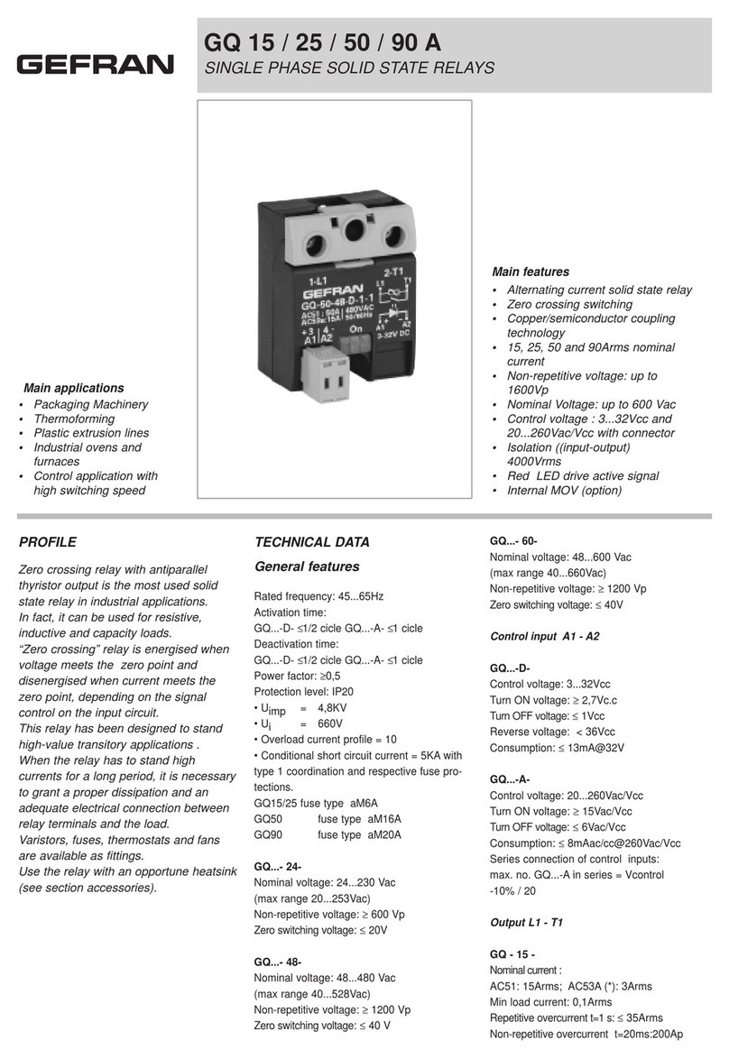
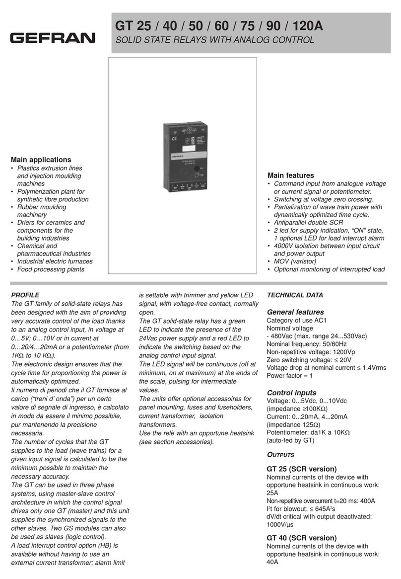
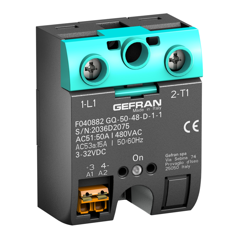
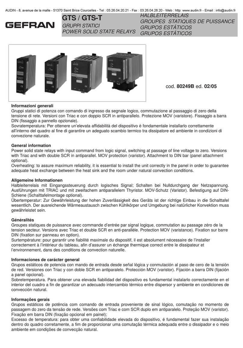
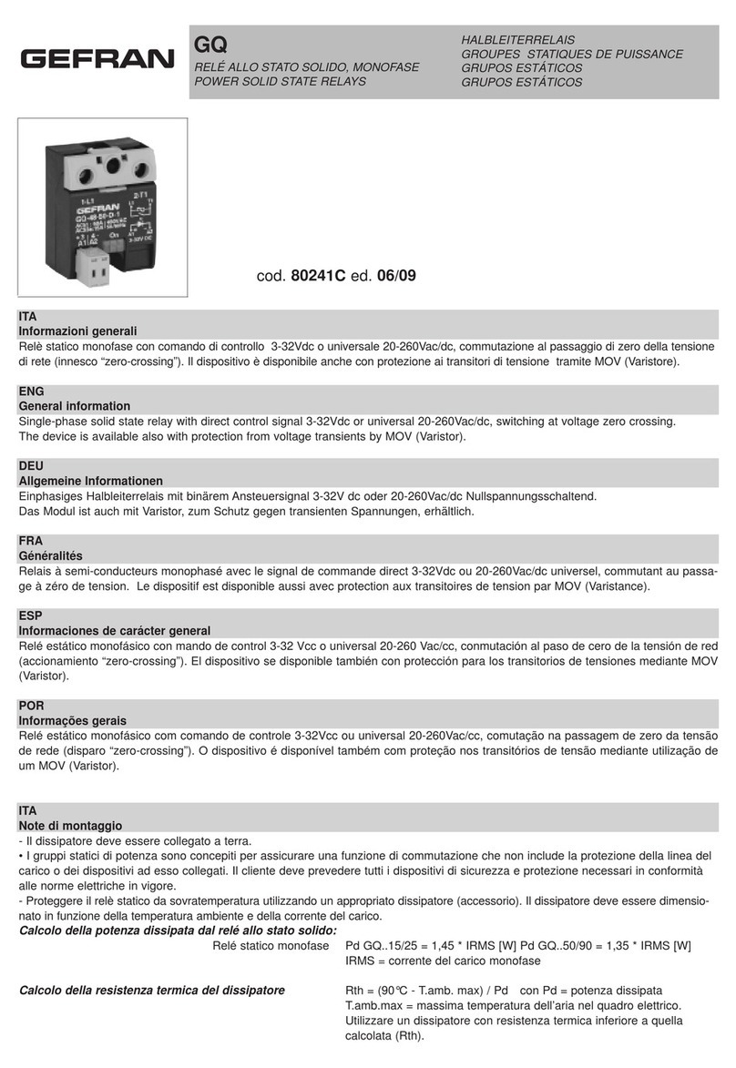
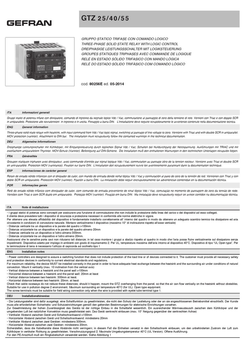
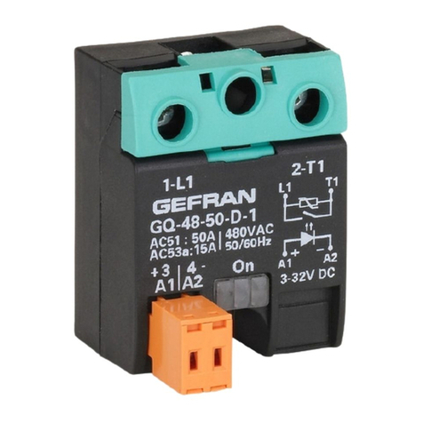
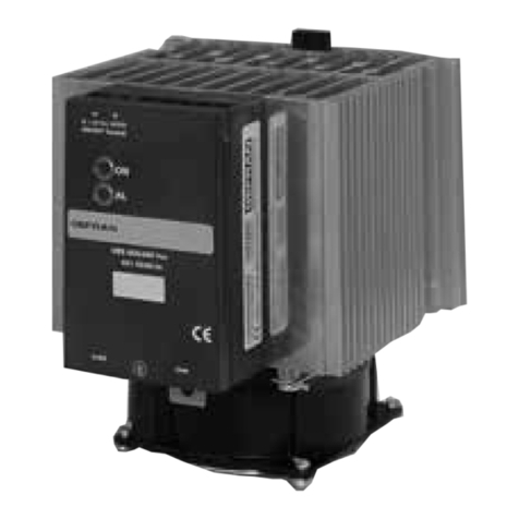
gefran GRP-H15A Owner's manual

For all specifics, documentation
and App for smarphone
CONFIGURATION AND
PROGRAMMING MANUAL
code: 81906_MAN_GRP-H_02-2022_ENG
STATIC POWER UNITS WITH PARTIAL LOAD BREAK,
LOGIC/ANALOG COMMAND AND IO-LINK COMMUNICATION
GRP-H 15/25/30/40/50/60/75/90/120A
81906_MAN_GRP-H_02-2022_ENG

81906_MAN_GRP-H_02-2022_ENG_pag. 2

81906_MAN_GRP-H_02-2022_ENG_pag. 3
TABLE OF CONTENTS
1. PRELIMINARY INSTRUCTIONS ..................... 5
1.1. Profile ....................................................................................5
1.2. Installation .............................................................................6
2. Installation and Connection ........................... 7
2.1. Dimensions and mounting measurements ............................7
2.2. DIN rail fixing .........................................................................8
2.3. Panel fixing ............................................................................9
2.4. Front view .............................................................................. 9
2.5. Pinout ..................................................................................10
2.5.1. Analogue control .......................................................10
2.5.2. Digital version ............................................................11
2.5.3. IO-Link control ..........................................................12
2.6. Load wiring .......................................................................... 13
2.7. Terminal and conductor table ..............................................14
2.8. Fan maintenance .................................................................15
3. CONFIGURATION .......................................... 16
3.1. Device configuration ...........................................................16
3.1.1. Gefran NFC application ............................................16
3.1.2. Configuration software and real-time checks ...........17
3.1.3. IO-Link ......................................................................17
3.1.4. Key ............................................................................18
4. PARAMETER DESCRIPTIONS ...................... 19
4.1. Inputs ..................................................................................19
4.1.1. Analogue input .........................................................19
4.1.1.1. Analogue input type .........................................19
4.1.1.2. Analogue input scale minimum limit ................19
4.1.1.3. Analogue input scale maximum limit ...............19
4.1.1.4. Analogue input correction offset ......................20
4.1.1.5. Analog input signal digital low-pass filter ........20
4.1.1.6. Fault Action Power ...........................................20
4.1.1.7. Analogue input value (process variable) .......... 20
4.1.1.8. Analogue input status ......................................21
4.1.2. Valore di corrente nel carico .....................................21
4.1.2.1. Current reading correction offset .....................21
4.1.2.2. Current reading low pass digital filter ............21
4.1.2.3. Current reading scale minimum limit ...............21
4.1.2.4. Current reading scale maximum limit ..............22
4.1.2.5. Real-time current reading input value ..............22
4.1.2.6. Current reading input value ..............................22
4.1.2.7. Current reading status .....................................22
4.1.3. Line voltage value .....................................................23
4.1.3.1. Voltage reading correction offset .....................23
4.1.3.2. Voltage reading low pass digital filter ..............23
4.1.3.3. Voltage reading update time ............................23
4.1.3.4. Voltage reading scale minimum limit ................23
4.1.3.5. Voltage reading scale maximum limit ...............24
4.1.3.6. Voltage reading input real-time value ...............24
4.1.3.7. Voltage reading input value ..............................24
4.1.3.8. Mains voltage frequency .................................. 24
4.1.3.9. Voltage reading status ......................................24
4.1.4. Values on load ...........................................................25
4.1.4.1. RMS load current .............................................25
4.1.4.2. Load voltage ....................................................25
4.1.4.3. Power on load ..................................................25
4.1.4.4. Load impedance ..............................................25
4.1.4.5. Consumed energy meter 1 ...............................25
4.1.4.6. Consumed energy meter 2 ...............................26
4.1.4.7. Energy meter reset ...........................................26
4.1.5. Digital input ...............................................................26
4.1.5.1. Digital input 1 function .....................................26
4.1.5.2. Digital input 1 type ...........................................27
4.1.5.3. Digital input 2 function .....................................27
4.1.5.4. Digital input 2 type ...........................................27
4.1.5.5. Digital input 1 function .....................................28
4.1.6. Key ............................................................................28
4.1.5.6. Front key enabling ............................................28
4.2. Alarms .................................................................................29
4.2.1. HB (Heat Break) Alarm ..............................................29
4.2.1.1. HB alarm threshold teach-in function ..............29
4.2.1.2. Functional diagram ..........................................30
4.2.1.3. Enabling HB alarm ...........................................31
4.2.1.4. Enable memory for HB alarm
.........................................................................31
4.2.1.5. HB alarm functionB
.........................................................................31
4.2.1.6. Delay time for HB alarm activation .................. 32
4.2.1.7. HB alarm threshold ..........................................32
4.2.1.8. Current Hb.tr alarm threshold ..........................32
4.2.1.9. Calibration status .............................................32
4.2.1.10. Alarm states .....................................................33
4.2.1.11. Detailed HB alarm status ................................. 33
4.2.1.12. Calibration command .......................................33
4.2.1.13. HB alarm threshold percentage .......................34
4.2.1.14. Current reading in HB calibration .....................34
4.2.1.15. Voltage reading in HB calibration .....................34
4.2.1.16. Power read in HB calibration ...........................34
4.2.1.17. Alarm reset ......................................................35
4.2.2. Allarme di Power Faut ...............................................35
4.2.2.1. Enabling Power Fault alarms ...........................35
4.2.2.2. Enable memory for Power Fault alarms ........... 36
4.2.2.3. SSR_SHORT update time ................................36
4.2.2.4. NO_VOLTAGE and NO_CURRENT alarm filter ..
36
4.2.2.5. Alarm states ...................................................37
4.2.2.6. Alarm reset .....................................................37
4.2.3. Thermal protection alarm ..........................................38
4.2.3.1. SSR temperature ..............................................38
4.2.3.2. SSR temperature derivative .............................38
4.2.3.3. SSR temperature derivative .............................38
4.3. Counters ..............................................................................39
4.3.3.1. HB alarms counter 1 ......................................39
4.3.3.2. HB alarms counter 2 ....................................39
4.3.3.3. Counter reset .................................................39
4.3.3.4. Overheat event counter 1 ...............................39
4.3.3.5. Overheat event counter 2 ...............................40
4.3.3.6. Counter reset .................................................40
4.3.3.7. Max temperature value reached 1 .................40
4.3.3.8. Max temperature value reached 2 ..................40
4.3.3.9. Reset Max temperature value ......................41
4.4. Output ................................................................................42
4.4.3.1. Reference for output 1 .....................................42
4.4.3.2. Output type 1 ...................................................42
4.5. LED ......................................................................................43
4.6. Automatic/manual control ...................................................44
4.6.3.1. Automatic/Manual status .................................44
4.6.3.2. Manual power percentage value ......................44
4.6.3.3. Percent value of delivered power .....................44
4.7. Power control ......................................................................45
4.7.3.1. Trigger modes .................................................. 45
4.7.3.2. Phase Angle (PA) Mode ....................................46
4.7.3.3. Softstart ...........................................................47
4.7.3.4. Trigger modes .................................................. 48
4.7.3.5. Minimum number of Burst Firing cycles ..........48
81906_MAN_GRP-H_02-2022_ENG_pag. 4
4.7.3.6. SSR output cycle time .....................................49
4.7.1. Soft start ramp settings ............................................49
4.7.1.1. Soft start enabling ............................................49
4.7.1.2. Soft start ramp duration ................................... 49
4.7.1.3. Soft start ramp reactivation time ......................50
4.7.1.4. Soft start ramp status ......................................50
4.8. Hardware and Software Information ...................................50
4.8.1.1. Software version ..............................................50
4.8.1.2. Manufacturer identifier .....................................50
4.8.1.3. Model identifier ................................................51
4.8.1.4. Serial number .................................................. 51
4.8.1.5. Product code (Fxxxxxx order code) .................51
4.8.1.6. Last modification user ...................................... 51
4.8.1.7. Hardware card recognition ............................... 52
4.8.1.8. Hardware card recognition 1 ............................ 52
4.8.1.9. Options installed ..............................................52
5. IO-Link ............................................................ 53
5.1. IO-Link .................................................................................53
5.2. IO-LINK INSTALLATION AND ELECTRICAL CONNECTIONS
53
5.2.1. Electrical installation .................................................53
5.3. CONTROL MODE ................................................................54
5.3.1. IO-Link information ...................................................54
5.3.2. SIO mode and IO-Link mode ....................................54
5.3.3. Process data mapping ..............................................55
5.3.4. Setting data ............................................................... 56
6. TECHNICAL SPECIFICATIONS ..................... 62
6.1. Technical specifications ......................................................62
6.2. Derating curves ...................................................................64
6.3. Downgrade with installation distance .................................65
6.4. Extrarapid fuses ..................................................................66
6.5. Accessoires .........................................................................66
6.6. Fans (for 90A/120A models only) ........................................66
6.7. Order code ..........................................................................67
6.8. EMC standards ...................................................................68
6.9. Warnings .............................................................................69
7. Certifications ................................................. 69
7.1. Certifications .......................................................................69

81906_MAN_GRP-H_02-2022_ENG_pag. 5
1. PRELIMINARY INSTRUCTIONS
1.1. Profile
The correct management of electric heaters and infra-
red lamps for industrial heating applications requires
robust, safe, fast and diagnostic-capable static con-
tactors.
The range of solid state contactors with heatsink
GRP-H meets all these needs, with current ratings
from 15 to 120 Ampere, voltages up to 600Vac, in
extremely compact dimensions in every single size.
The thermal design of all models guarantees the con-
tinuous supply of the rated current at an ambient tem-
perature of 40°C / 104°F through high efficiency heat
sinks, assisted by fans for the 90A and 120A models.
The derating curves show how higher current values
can also be obtained for lower temperatures as well as
the possibility of mounting various devices stacked on
the DIN rail.
CONFIGURATION AND DIAGNOSTICS
For the configuration of the GRP-H series devices, an
App is available for smartphones with Android and iOS
operating systems, which can be downloaded free of
charge from the relative stores. The App interfaces to
the device via contactless NFC (Near Field Communi-
cation) technology via a small NFC Dongle (which can
be ordered as part of the device or as an accessory).
It is also possible to read diagnostic data on the opera-
tion of the load and the device (energy meters, current
peaks or over-temperatures), duplicate or share the
configurations of multiple devices through this inter-
face.
The IO-Link interface guarantees efficient commu-
nication, capable of powering, configuring, moni-
toring and controlling the device, via only 3 wires.
Complete and simple device configuration is possible
with IODD files.
The devices can also be configured using a special
cable via PC and the GF_eXpress configuration tool.
Alternatively, basic device configuration is made avail-
able by means of a button and LED on the front.
The current thresholds for partial load break alarms
can be adjusted by means of a front key or digital input,
so that multiple objects can be configured at the same
time with the electrical panel closed.
CONTROL
The GRP-H series can be controlled in three different
ways based on the options chosen:
1. Logic signals in V DC, OnOff mode.
2. Analogue signal configurable as 0..5V, 0..10V,
0..20mA, 4..20mA and potentiometer, for proportional
commands (Burstfiring, FixedCycleTime, HalfSingle-
Cycle, PhaseAngle).
3. Control via the IO-Link point-to-point communication
protocol for comprehensive process diagnostics.
All commands are managed via push-in connectors,
for faster and easier connection, even without tools.
The device status is always displayed by a multi-co-
lour LED on the front panel, for an immediate view of
its operation. In the event of an error in the command
signal, a fault power can be programmed which the
device will maintain until the signal is restored.
POWER CONNECTIONS
Both the line voltage terminal available on the upper
part of the device and the load terminal on the lower
part are of the “cage” type, which offers the best and
safest seal even for cables of different cross-sections,
whether mounted with a cable lug or simply stripped.
DIAGNOSTICS AND ALARMS
It is increasingly vital for operators and maintainers
to recognize possible anomalies in the system imme-
diately and solve them quickly in order to ensure the
efficiency and profitability of machinery and plants.
The GRP-H series offers complete availability of load
information.
The physical alarm output, PNP type, is ready to diag-
nose partial or total load breaks, lack of voltage on the
load and over-temperature (configurable output). The
thermal alarm is triggered if heat dissipation exceeds a
critical threshold, signalling it with a red led on the front
panel, interrupting the power supply and triggering the
alarm output.
This function is always present, on all current sizes.

81906_MAN_GRP-H_02-2022_ENG_pag. 6
ENG Installation notes
Use the extra-rapid fuse shown in the catalogue
according to the connection example supplied.
Applications with uninterruptible power supply
units must also include a safety circuit breaker
for disconnecting the power line from the load.
To obtain high device reliability, it is essential
to install it correctly inside the panel in order to
obtain adequate heat exchange between the
heat sink and the surrounding air under condi-
tions of natural convection.
Mount the device vertically (maximum 10° incli-
nation from the vertical axis)
• Vertical distance between a device and the
panel wall >100mm
• Horizontal distance between a device and the
panel wall at least 20mm
• Vertical distance between one device and
another at least 100mm.
• Horizontal distance between one device and
another at least 20mm (in the event of installa-
tion at shorter distances, see derating curves).
Make sure that the cable ducts do not reduce
these distances; in this case, mount the units
overhanging the panel, so that the air can flow
vertically on the heat sink without hindrance.
limitations of use
• Ambient temperature limits, depending on der-
ating curves.
• Need for air exchange with the outside or an air
conditioner to transfer the dissipated power to
the outside of the panel.
•
Installation limits (distances between devices
to ensure dissipation under natural convection
conditions)
•
Maximum voltage limits and derivative of the
transients present on the line, for which the
static unit provides internal protection devices
(depending on the models).
•
Presence of leakage current < 3mA (max.
value with nominal voltage and junction tem-
perature of 125°C / 257°F).
1.2. Installation

81906_MAN_GRP-H_02-2022_ENG_pag. 7
55 / 2,17"
140 / 5,12" with FAN 24VDc
145 /5,71" with FAN 110/220VAc
110 / 4,33"
95 / 3,54"
70703517.517.5
90 / 3,54"
= =
102.8 / 4,06"
137.8 / 5,4"
137.8 / 5,4"
137.8 / 5,4"
137.8 / 5,4"
0,69" 0,69" 1,38" 2,76" 2,76"
154 /6,06"
2,76"
70
60x60
2,36x2,36"
80x80
3,15x3,15"
137.8 / 5,4"
44.05 /1,5"
102 /4,01"
n4.5 /0,18"
4.5 /0,18"
4.5 /0,18"
4.3
0,17"
4.3
0,17"
4.3
0,17"
4.3
0,17"
4.3
0,17"
4.3
0,17"
70
2,76"
137.8 / 5,4"4.3
0,17"
mm
mm
mm
mm
mm
mm
mm
mm
mm
mm
mm mm
mm
mm
60A
75A
15-25A 30A 40-50A 60A
90A ALL FAN OPT.
120A FAN62 / FAN63
mm mm mm mm mm
mm
mm
mm
120A
FAN60 / FAN61
mm
24VDc 25 / 1"
110/220VAc 30 / 1,18"
mm
mm
mm
mm
mm mm
mm
mm
mm
mm
15-25A 30A 40-50A 75A
90-120A
FAN62 / FAN63
120A
FAN60 / FAN61
PANEL FIXATION
15-120A
mm
mm
mm
mm
2. INSTALLATION AND CONNECTION
2.1. Dimensions and mounting measurements

81906_MAN_GRP-H_02-2022_ENG_pag. 8
2.1
0,06"
8
0,031"
4.3 /4,17" 103 /4,06"
110 /4,33"
UNLOCKING
SLIT
PE SCREW
M5x8 MAX
M5x0,31" MAX
mm
PE WIRE
AWG10 / 5mmq
mm mm
mm
mm
mm
1
212
SCREW DRIVER (*)
DIN rail coupling sequence DIN rail release sequence
(*) Use of a slotted screwdriver with a max. diameter of 6mm is recommended
2.2. DIN rail fixing

81906_MAN_GRP-H_02-2022_ENG_pag. 9
4.5
0,18"
102 / 4,02"
Fixing Screw
Length=10 /0,39" min.
4.5
0,18"
Ø 4.5
mm
Ø 0,18"
Ø 4
mm
Ø 4
mm
Ø 0,16" Ø 0,16"
17.5
103 / 4,06"
110.6 / 4,33"
0,69"
4.3
0,17"
PE SCREW
M5x8 MAX
M5x0,31" MAX
PE WIRE
AWG10 / 5mmq
mm
mm
mm
mm
mm
mm
mm
TOP
VIEW
mm
mm
GRP
15-60A
PROGRAM
BUTTON
-
USB/NFC
-
SCR ON
LED
GREEN
-LED GREEN RUN
LED RED ALARM
LED BLUE STATUS
-
GRP
75-120A
SCR ON
LED
GREEN
LED GREEN RUN
LED RED ALARM
LED BLUE STATUS
-
PROGRAM
BUTTON
-
USB/NFC
-
2.3. Panel fixing
2.4. Front view

81906_MAN_GRP-H_02-2022_ENG_pag. 10
AL
24V
L1
N/L2
PE
L1
N/L2
PE
+ -
POT
DIG AUX
Controller
Load
Fuse
Fuse
GG
Fuse
GG
Analog ouput
0-20 / 4-20 mA
0-5 / 0-10 V
Connection for single phase load
Fuse: fast fuse, see fuse table
Fuse gg: see fuse section
2.5. Pinout
VERSION WITH ANALOGUE INPUT
2.5.1. Analogue control
Power terminals
Ref. Description Notes
1/L1 Line Connection
2/T1 Load Connection
AN version signal connector (analogue input)
3/A2- Power GND
4/Us + V DC power supply
GRP-H power supply (Range from 10 to 30 V DC, Imax = 20 mA at 24V)
GRP-H-90 ..120A-..FAN63: GRP-H + Fan power supply
(Range from 20 to 27 V DC, Imax <150 mA at 24V with Fan active)
5/Vp Potentiometer power supply output (+ 5Vdc) /
Auxiliary digital input
Potentiometer output voltage: 5V DC, Iout max = 10mA
Digital input: 5-30V max 3 mA
6/A+ Analogue differential command input
7/A-
8/A2- GND alarm output
(common to terminal 3/A2-)
9/AL Alarm output Digital output normally off (settable with normally on).
PNP type, output voltage: Us(24Vdc)-0.7Vdc, Iout max =15mA

81906_MAN_GRP-H_02-2022_ENG_pag. 11
AL
24V
DIG AUX
+ -
L1
N/L2
PE
L1
N/L2
PE
Digital output
Controller
Load
Fuse
Fuse
GG
Fuse
GG
Fuse: fast fuse, see fuse table
Fuse gg: see fuse section
Connection for single phase load
VERSION WITH DIGITAL INPUT
2.5.2. Digital version
Power terminals
Ref. Description Notes
1/L1 Line Connection
2/T1 Load Connection
Connettore di segnale versioni D (ingresso digitale)
3/A2- Power GND
4/Us + V DC power supply
GRP-H power supply (Range from 10 to 30 V DC, Imax = 20 mA at 24V)
GRP-H-90..120A-..FAN63: GRP-H + Fan power supply
(Range from 20 to 27 V DC, Imax <150 mA at 24V with Fan active)
5/DI Auxiliary digital input Digital input: 5-30V max 3 mA
6/A1+ Command digital input Digital input: 5-30V max 3 mA
7/A2- GND command input
(common to terminal 3/A2-)
8/A2- GND alarm output
(common to terminal 3/A2-)
9/AL Alarm output Digital output normally off (settable with normally on).
PNP type, output voltage: Us(24Vdc)-0.7Vdc, Iout max =15mA

81906_MAN_GRP-H_02-2022_ENG_pag. 12
MASTER
IO-LINK
AL
24Vdc
+
IO
LINK
L1
N/L2
PE
L1
N/L2
PE
Load
Fuse
Fuse: fast fuse, see fuse table
Fuse gg: see fuse section
Connection for single phase load
Fuse
GG
Fuse
GG
VERSION WITH IO-LINK INPUT
2.5.3. IO-Link control
Power terminals (common to all versions)
Ref. Description Notes
1/L1 Line Connection
2/T1 Load Connection
I version signal connector (IO-LINK)
3/L- Power GND
4/L+ + V DC power supply
GRP-H power supply (Range from 10 to 30 V DC, Imax = 20 mA at 24V)
GRP-H-90..120A-..FAN63: GRP-H + Fan power supply
(Range from 20 to 27 V DC, Imax <150 mA at 24V with Fan active)
5/C/Q IO-LINK communication line
8/L- GND alarm output
(common to terminal 3/L-)
9/DQ Alarm output Digital output normally off (settable with normally on).
PNP type, output voltage: Us(24Vdc)-0.7Vdc, Iout max =15mA

81906_MAN_GRP-H_02-2022_ENG_pag. 13
R
R
R
L2
L3
PE
L1
N
L2
L3
PE
L1
N
Load Star
Fuse
Fuse
Fuse
Connect the control signals (analog or digital) on all the devices as shown in the specific section
GRP 1 LOAD 1
GRP 3
LOAD 3
GRP 2
LOAD 2
L1
L2
L3
V
L3
PE
L2
L1
L3
PE
L2
L1
Load open delta
Connect the control signals (analog or digital) on all the devices as shown in the specific section
Fuse
Load 3
Load 2
Load 1
Fuse
Fuse
2.6. Load wiring
CONNECTION FOR THREE-PHASE STAR WITH NEUTRAL LOAD
CONNECTION FOR THREE-PHASE OPEN DELTA LOAD

81906_MAN_GRP-H_02-2022_ENG_pag. 14
2.7. Terminal and conductor table
CONTROL/SIGNAL TERMINALS
Rigid/flexible / cable lug conductor cross section
1 Conductor section
2 Conductors section
1 x 0.2-1.5 mm2/
2 x 0.1-0.75 mm2
1 x 24-16 AWG
2 x 27-19 AWG
Stripping length 8 mm
Nota: Usare conduttori in rame (CU) 60/75°C (140/167°F), rigidi o multifilari
GROUND TERMINAL
Contact area (WxD) screw type 9 x 9 mm
M5
Tightening torque 1,5-2,5 Nm
(13.3 lb-in – 22 lb-in)
POWER TERMINALS
Rigid/flexible / ferrule conductor cross section
Size 15A 25A 30A 40A 50A 60A 75A 90A 120A
Contact area (WxD) screw type 9,2 x 8 mm
M5
10,5 x 10,7 mm
M5
Stripping length 11 mm 13 mm
1 Conductor section
2 Conductors section
1 x 2.5 mm2/
2 x 1.5 mm2
1 x 6 mm2/
2 x 4 mm2
1 x 10 mm2/
2 x 6 mm2
1 x 16 mm2/
2 x 10 mm2
1 x 25 mm2/
2 x 16 mm235 mm21 x 50 mm2/
2 x 25 mm2
1 x 14 AWG /
2 x 17 AWG
1 x 10 AWG /
2 x 12 AWG
1 x 8 AWG /
2 x 10 AWG
1 x 6 AWG /
2 x 8 AWG
1 x 4 AWG /
2 x 6 AWG
1 x 3 AWG /
2 x 6 AWG 2 AWG 1 x 1/0 AWG
/ 2 x 3 AWG
Tightening torque 2,5-3 Nm
(22-26,6lb-in)
Note: Use 75°C (167°F) copper (CU), multi-stranded conductors
- (*) The screw terminals are only suitable for on-site wiring connection when the wire is equipped with a tube terminal with eyelet.
It is possible to make ground connection using a copper bar suitably ground connected and fixed to the heatsink of more GRP-H.
(WxD) = Width x depth

81906_MAN_GRP-H_02-2022_ENG_pag. 15
REMOVE
CONNECTOR
REMOVE
CONNECTOR
REMOVE
SCREW
1
REMOVE
SCREW
2
3
CONNECT
FAN-CABLES
2
FIX NEW FAN
BY SCREW 2
1
FIX NEW FAN
BY SCREW 1
3
FIX
CONNECTOR
ON PCB
2
FIX NEW FAN
BY SCREW 2
1
FIX NEW FAN
BY SCREW 1
2.8. Fan maintenance
Caution: make sure that the arrow showing the direction of the air flow on the fan is pointing toward the dissipater
Use a Phillips screwdriver with a MAX 3.5mm diameter.

81906_MAN_GRP-H_02-2022_ENG_pag. 16
Some basic settings can be set using the key on the
front of the device.
The complete configuration can be completed via the
“Gefran NFC” smartphone application, via PC with
GF_eXpress software or via IO-Link. Configuration
via Smartphone and with cable from PC can also be
performed with the device not powered.
The Gefran NFC application can be downloaded
from the Play Store for Android devices and from the
AppleStore for iOS devices.
NFC (Near Field Communication) must be enabled on
the smartphone. It can be enabled from the settings
(or quick settings in the drop-down menus) commonly
the logos are the following:
or
This technology permits wireless exchange of
data from one device to another (Smartphone <-
-> GRP), only when they are at close range. The
same technology is used daily to read TagNFC,
“Contactless” payment with credit cards and
smartphones, etc. Data is exchanged by placing the
smartphone NFC antennas a few mm from the Gefran
NFC Dongle (see table "6.5. Accessoires" on page
66).
The NFC Dongle must be inserted into the microUSB
port on the front of the device. All GRP
devices are enabled to read and write
data via NFC Dongle. The dongle can
be ordered as an accessory or directly in
the GRP order code. It can be removed
after use or left inserted. The NFC
Dongle is not the device memory, but
an antenna, which allows communication at close
range.
The application can read/write configuration
recipes, model information and diagnostic data.
The application allows you to open recipes on the
smartphone memory, read them from the device and
retransmit them to it or similar devices. Recipes in
.gfe format can also be saved and forwarded (Gefran
format common to GF_eXpress recipe files).
All the reading and writing operations can be
performed with the device powered or NOT
powered.
This is possible thanks to the powered supplied by the
smartphone to the internal GRP memory during NFC
connection. Recipes are written on a GRP device in
two ways:
Powered Device: the recipe is written via the
smartphone in a portion of the device memory
dedicated to writing via NFC. Immediately afterwards,
the GRP device automatically checks the validity and
consistency of the data transmission. These checks
ensure that, even in the event of communication
disturbances or interruptions, the GRP and the
information within it are protected. If the check
fails, the transmitted data is ignored and the GRP
continues to work with the original recipe. If the
checks are passed, the device loads the recipe
transmitted from the NFC write memory to the
memory that contains the recipe used for operation.
To know the results of the data transmission, check
the section "4.5. LED" on page 43.
Device NOT powered: the recipe is written via
the smartphone in a portion of the device memory
dedicated to writing via NFC. At first start-up, the
checks described above are carried out in the case of
“Device powered”.
3. CONFIGURATION
3.1. Device configuration
3.1.1. Gefran NFC application

81906_MAN_GRP-H_02-2022_ENG_pag. 17
The connection between PC and GRP via cable
allows you to configure, read and acquire the data
read from the field in real-time (measured voltage,
current, power, alarms and device status etc. ).
The GF_eXpress configuration software allows the
complete configuration of the GRP using a USB
converter cable (F060800), which can be ordered as
a Gefran accessory.
For more information on programming with a PC, see
the GF_eXpress documentation available at www.
gefran.com.
Caution! A high level of knowledge of the problems
and techniques for controlling electricity is required to
correctly configure the GRP device so that it meets
the application needs.
Caution! Before commissioning the GRP device, the
user must ensure the parameters are set correctly
to avoid damages to persons or property. If you are
unsure of your skills or not fully aware of the potential
consequences of incorrect parameter settings, we
advise you not to proceed with the configuration. If in
doubt, or if you would like some clarification, please
visit www.gefran.com or contact the Gefran Customer
Care service.
The GRP device can be fully configured, controlled
and monitored via the IO-Link point-to-point
communication protocol. The IODD files characteristic
of the device can be downloaded from www.gefran.
com, from the page dedicated to the GRP device.
For details of all parameters and commands available
in IO-Link, refer to section "5. IO-Link" on page 53
3.1.2. Configuration software and real-time checks
3.1.3. IO-Link

81906_MAN_GRP-H_02-2022_ENG_pag. 18
Some basic settings can be edited or the load current
calibration phase started using the key and the LEDs
on the front of the object. The basic settings are:
• “Partial HB alarm threshold learning” command See
chapter Allarme HB (Heater Break) ”4.2.1.1. HB
alarm threshold teach-in function” on page 29
(for GRP-x-x-x-x-1-x-x-x-x-x models)
• Number of loads in parallel under a single zone
for calculating the partial HB alarm threshold (see
parameter Hb.P) (for GRP-xxxx-1-xxxxx models)
• Type of analogue input (see tyP parameter) (for
GRP-xxx-AN-xxxxxx models)
• Minimum number of cycles of the Burst Firing mode
(see parameter bF.Cy) (only if hd.5 = BF).
• Full scale potentiometer calibration
• Alarm memory reset
Below are the instructions to change settings via key
and feedback from the front LED.
With the key released for at least 30 s (15 s if you are
in the phase of indicating the setting to be modified)
you return to normal operation.
* The device does NOT automatically enable the power output after the HB calibration is applied.
The device waits for the command signal (digital signal ON, analogue or IO-Link is recommended > 50%). A
few operating waves are enough for the device to register the current and voltage value as the nominal value
of the load and exit calibration.
It is recommended to carry out calibration in load regime conditions. This is to avoid false alarms due to current
drop, not due to load break in parallel, but to the consumption of different current between resistors at room
temp. and working temp.
Normal operations resume with the key released for at least 15s.
In Heater Break or Power Fault with memory alarm
conditions, the alarm memory can be reset by
pressing the key according to the flow illustrated
below:
NORMAL
OPERATION
LED: on or flashing as
indicated in the
LED chapter
LED status
with key
pressed
Key
pressed
Key pressed > 3 s
and then released
Key
repeatedly
pressed and
released
> 0.2 s
Key pressed > 9 s
and then released
Key pressed > 3 s
and then released
Key pressed > 15 s
and then released
Key
repeatedly
pressed and
released
> 0.2 s
Key pressed > 3 s
and then released
Key pressed > 3 s
and then released
Key
repeatedly
pressed and
released
> 0.2 s
Key
pressed
> 6 s
Key
pressed
> 12 s
3 s
3 s 3 s 3 s
3 s
SETTINGS TO MODIFY NUMBER
OF LOADS (HB.P) and
CALIBRATION HB
(for model GRP-Hxxx-1-xxxxxx only)
GREEN LED: on
SETTINGS TO MODIFY
ANALOGUE INPUT TYPE (TYP)
and CALIBRATION OF FULL
SCALE POTENTIOMETER
(for model GRP-Hxxx-1-xxxxxx only)
RED LED: on
SETTINGS TO MODIFY THE
NUMBER OF MINIMUM START
CYCLES (BF.CY)
(only if hd.5 = BF)
BLUE LED: on
NUMBER OF
LOADS INDICATION
GREEN LED: it flashes according
to the value of Hb.P
ANALOGUE INPUT TYPE
INDICATION
RED LED: flashes according
to the tyP value
MINIMUM NUMBER OF START
CYCLES INDICATION
BLUE LED: flashes according
to the value of bF.CY
NUMBER OF LOADS
CONFIRMATION
GREEN LED: quickly
flashes for 1s
NUMBER OF LOADS
DATA ENTRY
GREEN LED: turns on by
pressing the key and turns off
by releasing the key
ANALOGUE INPUT
TYPE DATA ENTRY
RED LED: turns on by
pressing the key and turns off
by releasing the key
ANALOGUE INPUT TYPE
CONFIRMATION
RED LED: quickly flashed
for 1s
GREEN LED RED LED BLUE LED
MINIMUM NUMBER
OF START CYCLES
CONFIRMATION
BLUE LED: quickly
flashes for 1s
MINIMUM NUMBER
OF START CYCLES
DATA ENTRY
BLUE LED: turns on by
pressing the key and turns off
by releasing the key
FULL SCALE
POTENTIOMETER
CALIBRATION ON
(for tyP = 6 only)
HB
CALIBRATION ON
(*)
3 s
Key
pressed
Key
pressed
Key pressed > 1 s
and then released
1 s
HB or PF ALARM MEMORY
RESET SETTING
RED LED: on
MEMORY RESET
CONFIRMATION
RED LED: quickly flashed for 1s
RED LED
OPERATION
WITH HB or PF
ALARM ON
LED: on or flashing as
indicated in the
LED chapter
3.1.4. Key

81906_MAN_GRP-H_02-2022_ENG_pag. 19
Settings
4.1.1.1. Analogue input type
Acronym App / GF_eXpress menu Attribute Retentive U.M. Default
Description
tyP Inputs Analog input R/W ■1
The parameter sets the type of analogue input.
Options:
0Input disabled
1 0...10V
2 0...5V
3 0...20mA
4 4...20mA
5 Potentiometer
6Potentiometer with custom calibration (*)
(*) full scale calibration only, activated by key
4.1.1.2. Analogue input scale minimum limit
Acronym App / GF_eXpress menu Attribute Retentive U.M. Default
Description
Lo.S Inputs Analog input R/W ■s.p. 0.0
The parameter sets the analogue input scale minimum limit.
min...max: -100.0...+200.0
4.1.1.3. Analogue input scale maximum limit
Acronym App / GF_eXpress menu Attribute Retentive U.M. Default
Description
HI.S Inputs Analog input R/W ■s.p. 100.0
The parameter sets the analogue input scale minimum limit.
min...max: Lo.S...+200.0
4. PARAMETER DESCRIPTIONS
4.1. Inputs
4.1.1. Analogue input
Available only for GRP-x-x-x-AN-x-x-x-x-x-x model

81906_MAN_GRP-H_02-2022_ENG_pag. 20
4.1.1.4. Analogue input correction offset
Acronym App / GF_eXpress menu Attribute Retentive U.M. Default
Description
oFS Inputs Analog input R/W ■s.p. 0.0
The parameter sets the analogue input correction offset.
min...max: -99.9...99.9
4.1.1.5. Analog input signal digital low-pass filter
Acronym App / GF_eXpress menu Attribute Retentive U.M. Default
Description
FLt Inputs Analog input R/W ■s 0.1
The parameter sets the time of the low pass filter on the analogue input signal.
min...max: 0.0 ...20.0 s
4.1.1.6. Fault Action Power
Acronym App / GF_eXpress menu Attribute Retentive U.M. Default
Description
FA.P Controls R/W ■% 0.0
The parameter sets the power to be supplied in the event of an analogue input fault.
When a 4 ... 20 mA input is used and the current is less than 2 mA, the Err state is generated and the
power defined in FA.P is supplied.
min...max: 0...100.0 %
Status
4.1.1.7. Analogue input value (process variable)
Acronym App / GF_eXpress menu Attribute Retentive U.M. Default
Description
P. V. Status R - s.p. -
Analogue input engineering value read (process variable).
This manual suits for next models
8
Table of contents
Other gefran Relay manuals

gefran
gefran GTS User manual

gefran
gefran GTT 25/230 User manual

gefran
gefran GQ 15 A User manual

gefran
gefran GQ Series User manual

gefran
gefran GTZ-25 Series User manual

gefran
gefran GTS User manual

gefran
gefran GQ Series User manual

gefran
gefran GTZ 25 Configuration guide

gefran
gefran GQ 15 A Series Instruction manual

gefran
gefran GTZ 25 Quick start guide