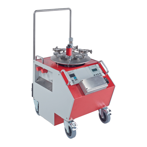
Pfeiffer Vacuum E-PDQ User manual

i
Programming and Operation Manual
Leak Test Instrument
Model E-PDQ
Firmware Revision 2.3.14 or 2.3.15
Hardware Revision A
July 6, 2021
Manual Revision 1.5
Proprietary Note:
The IGLS, Mass Extraction Technology, Adaptive Test and Leak-Tek ©, Leak-Rx© programs are
proprietary products belong to ATC, Inc. and are protected by existing patents (5,861,546;
6,3085,56B1; 6,584,828B; ,6,854,318B2; 7,231,811,EP1-356-260-B1) as well as other US and
International pending patents. The Leak-Tek program©, Leak-Rx© program, Adaptive Test Utility
Program© and ATC Model-EPDQ are protected by international copyright laws.
© 1995-2015 ATC, Inc. All rights reserved.
This manual should not be copied or transferred to any third party without ATC’s written consent.

ii
TABLE OF CONTENTS
TABLE OF FIGURES.......................................................................................... IV
1. INTRODUCTION ..............................................................................................1
1.1 PRINCIPLE OF OPERATION............................................................................................................ 2
2. FUNCTION CONFIGURATION ........................................................................4
2.1 CONVENTIONAL LEAK TEST ................................................................................................................. 4
2.2 ADAPTIVE LEAK TEST........................................................................................................................... 4
2.3 REMOTE START AND STOP.................................................................................................................... 4
3. INTERFACE......................................................................................................5
3.1 MECHANICAL INTERFACE AND CONNECTION OF THE MODEL E-PDQ: .................................. 5
3.2 ENVIRONMENTAL CONDITIONS: ................................................................................................. 7
3.3 ELECTRICAL INTERFACE AND CONNECTION:.......................................................................... 8
3.4 GUIDELINE FOR PNEUMATIC INTERFACE..............................................................................................12
3.5 GUIDELINE FOR SETTING UP MODEL E-PDQ INSTRUMENT...................................................................13
3.6 VERIFICATION PROCEDURE..................................................................................................................14
4. MODEL E-PDQ OPERATION SEQUENCE....................................................15
5. COMMUNICATION PROTOCOL....................................................................17
5.1 CONVENTIONAL COMMANDS FOR SENSOR PARAMETERS ....................................................................17
5.2 DAQ COMMANDS................................................................................................................................17
5.3 STEP NUMBER......................................................................................................................................22
6. MAINTENANCE AND TROUBLESHOOTING ................................................24
6.1 PERIODIC MAINTENANCE AND CALIBRATION ......................................................................................24
6.1.1 Periodic Calibration....................................................................................................................24
6.1.2 Leak Test Instrument performance Verification ..........................................................................24
7.2 TROUBLESHOOTING .............................................................................................................................26
APPENDIX A - COMMAND LIST........................................................................29
A.1 AGROUP.............................................................................................................................................29
A.2 BGROUP.............................................................................................................................................29
A.3 C-GROUP ............................................................................................................................................29
A.4 DGROUP.............................................................................................................................................30
A.5 GGROUP.............................................................................................................................................30
A.6 HGROUP.............................................................................................................................................30
A.7 KGROUP.............................................................................................................................................30
A.8 LGROUP .............................................................................................................................................31
A.9 OGROUP.............................................................................................................................................31
A.10 PGROUP ...........................................................................................................................................31
A.12 SGROUP ...........................................................................................................................................32
A.13 TGROUP ...........................................................................................................................................33
A.14 U-GROUP ..........................................................................................................................................33
A.15 VGROUP...........................................................................................................................................36
A.16 XGROUP...........................................................................................................................................36
A.17 Y-GROUP ..........................................................................................................................................37
A.18 Z-GROUP...........................................................................................................................................37
APPENDIX B –MODEL E-PDQ ASSEMBLY DRAWING AND WIRING
DIAGRAM...........................................................................................................38

iii

iv
TABLE OF FIGURES
FIGURE 3.1.1 -PNEUMATIC DIAGRAM.......................................................................................................... 6
TABLE 3.2.1.................................................................................................................................................... 8
FIGURE 3.3.1 –REAR PANEL STANDARD REMOTE I/O CONNECTIONS ......................................................10
FIGURE 3.3.2 –STANDARD E-PDQ REMOTE I/O PIN CONNECTOR............................................................11
FIGURE 3.3.3 –LIST OF PASS AND FAILURE MODE WITH PIN OUTS...........................................................11
FIGURE 3.3.4 -SERIAL LOOP CONNECTION OF TWO MODEL E-PDQ INSTRUMENTS................................12
FIGURE 5.1 -STEP NUMBER INTERPRETATION ...........................................................................................23
FIGURE 7.2.1 -TROUBLESHOOTING.............................................................................................................28

v
WARNING:
This product deals with gas that will expand under pressure. Pressurized volumes
(components, hoses, etc.) should be handled with proper protection to avoid any harm to
the user.
WARNING:
Use this product for the purpose of leak testing or flow measurement and testing in the
pressure and temperature range specified, ONLY!
WARNING:
Only qualified personnel should install, or use this product. Installation must comply with
the manual requirements and product specifications.
WARNING:
Under no circumstances while the test is on should the operator tamper with the “unit
under test (UUT)”. This may result in bodily injury and/or erroneous results.
WARNING:
This product shall be used for leak test applications and/or flow measurement
applications only.
WARNING:
When this Leak Test Instrument is part of a leak test system, it is the user’s responsibility
to assure proper interface and maintenance in order for this instrument to utilize its
measurement capabilities safely and accurately.
CAUTION:
This instruments measurement reflects the momentary leak flow rate of the unit under
test at the present time and conditions. Any leak test cannot guarantee long term leak
tightness for products in actual operating conditions.
CAUTION:
The user shall be familiar with flow, pressure and temperature measurement units before
setting up the leak test instrument. It is the user’s responsibility to properly define leak
flow rates and tolerances for a specific application.
NOTE:
FUSE RATING: Incoming 24VDC supply is recommended to be fused at 2A for
overcurrent protection.

vi
CAUTION:
Incoming supply outside 24 VDC +/-10% and unable to source 2 Amps it NOT
recommended and may result in inaccurate results, product malfunction and/or damaged
electronics.

vii

INTRODUCTION
1
1. Introduction
This manual applies to the operation and maintenance of the Leak Test
Instrument Model E-PDQ incorporating the Intelligent Gas Leak Sensor (IGLS)
manufactured by:
Advanced Test Concepts 4037
Guion Lane
Indianapolis, IN 46268
317-328-8492
www.atcinc.net
The IGLS is a micro-flow gas sensor operating based on ATC’s patented
accelerated laminar flow design. The IGLS measures volume flow, pressure and
temperature. The instrument can operate using volume flow, mass flow, or
volume flow at std. conditions, by selecting one of 27 flow units and their
combinations. The IGLS is a microprocessor based system. The microcontroller
program performs on board volumetric (i.e. cc/min) or mass (e.g. g/min) flow
measurements with temperature and pressure compensation. The
microcontroller can total the flow during testing (i.e. total mg) using the mass
extraction concept. The IGLS has capabilities to control valve sequencing as
required for different applications and can operate as a stand-alone leak test
system with no PLC or PC control.
There are multiple options to interface to the Model E-PDQ. It can be operated
using digital I/O through the 15 pin interface or via Ethernet. The 15 pin interface
provides some additional flexibility which is not currently available through the
Ethernet interface.
The IGLS measures leak flow rates based on the mass conservation law. It
measures the amount of flow required to maintain constant pressure at a
constant temperature which is equal to the amount of flow leaking out. This
method offers quick test time with reduced sensitivity to unit under test volume.
LeakTek©is a software package that allows the user to configure applications
parameters as needed to meet testing requirements. This program can also be
used to view, save, and analyze test data using a PC. The LeakTek©program is
optional and is not required to operate the instrument.
The IGLS receives commands/data requests and returns data via a bi-directional
RS-232 port. The Model E-PDQ includes a female 9-pin D-connector on the rear
panel for connecting to a PC using a straight through RS-232 serial cable. Up to
9 IGLS (Model E-PDQ instruments) can be attached to a single RS-232 port.
The Model E-PDQ also includes an RJ45 Ethernet connector for PLC/PC
interface via a network connection either directly or through a LAN. Selection of

INTRODUCTION
2
the communication method is made via the COMM SELECT toggle switch
located on the right side of RS232 and Ethernet ports as shown in Appendix B.
Only one communications port may be used at any time. The Ethernet
connection does not support multiple user access to the instrument. Refer to the
Operation Manual for LeakTek©for network setup and instrument configuration
when using the Ethernet communications port.
Extensive programming commands allow the user to address any one of the
connected sensors in order to configure test parameters and update calibration
coefficients.
The E-PDQ instrument can be configured to run up to four (4) types. Each of the
4 test types can include different test parameters or set-ups. Test type can be
selected and verified via the rear 15 pin interface. All remote or external controls
(input and output) are available at the male 15 pin connector located on the rear
panel.
1.1 Principle of Operation
The Model E-PDQ and its accessories provide a complete solution for leak flow
testing. The leak test concept is based on the mass conservation law. Per this
basic law of physics, once the unit under test (UUT) is pressurized and reaches
steady state conditions, the amount of mass flow into the UUT equals the amount
of mass flow that is leaking out.
In other words, the IGLS measures make-up flow required to maintain steady
UUT pressure. In vacuum conditions the IGLS measures the mass flow extracted
from the UUT required to maintain a steady vacuum level.
The IGLS is a unique micro-flow sensor capable of measuring extremely low flow
rates due to ATC’s accelerated laminar flow design. The IGLS measures volume
flow and converts it to mass flow based on pressure, temperature, and gas type.
IGLS sensitivity is increased in vacuum conditions where a given mass flow
yields a larger volume flow due to the reduced gas density at low pressure. The
IGLS operates in the viscous and slip flow regimes, in pressure ranges of 13.8
kPa Absolute (~2 psia) to 448 kPa Abs (65 psia). When performing tests under
13.8 KPa absolute pressure the material transfer mechanism varies. For these
applications ATC’s Mass Extraction Instrumentation with the Intelligent Molecular
Flow Sensor (IMFS) is recommended.
Some significant advantages of IGLS technology is that the steady state leak
flow rate is independent of the UUT volume and the measurement is a direct leak
flow measurement. Frequent calibration is not required, while standard annual or
bi-annual calibration procedures are applicable. A verification orifice (sometimes
called “calibrated leak”) is used only to verify system and instrument integrity.

INTRODUCTION
3
The IGLS technology offers fast and repeatable leak tests. For shorter cycle time
the signature concept can be employed. The signature concept is described in
detail the LeakTek©software manual.

INTERFACE
4
2. Function Configuration
The IGLS can be used for several distinct applications as follows:
1. Conventional Leak Test: Automated leak testing with or without automatic
pressure control. (The Intelligent Gas Leak System or IGLS)
2. Adaptive Leak Test: Based on dynamic leak flow analysis, the sensor will
detect the leak flow result at any time during the leak test period depending on
the flow stability and leak detection criteria.
2.1 Conventional Leak Test
When functioning as a conventional leak tester the IGLS controls all signals to
the pneumatic valves which pressurize, stabilize, and test the UUT.
During the test step the IGLS will monitor flow readings for a pre-defined period
and make a pass/fail determination. Pressure and flow must be within defined
range to pass the test. The sequence will stop and flow will automatically shut
down if a pass occurs. A re-test function can be configured to allow a continuous
test until the pass criteria are met if there are details of the test part that can be
altered or adjusted to make the part stop leaking. The test status is displayed on
the 3 LED’s on the front of the instrument. All test parameters can be configured
via the RS-232 port or Ethernet port using the LeakTek©program or hyper-
terminal.
2.2 Adaptive Leak Test
If the leak rate of the majority of tests for the UUT is much smaller than the leak
tolerance the user can configure the sensor to dynamically analyze the flow
behavior and make an early detection to determine if the leak rate is going to be
significantly smaller or larger than the leak tolerance. In most cases, this will
significantly reduce the total test time.
2.3 Remote Start and Stop
The Model EPDQ and Leak Tek™ Software Versions of 6.08 and later includes a
remote start and stop button enabling Leak Tek program or ant PC program to
start the test from the Run Screen using serial or Ethernet communication. In
Firmware 2.3.15 and later, the remote start and stop function must be configured,
as the default setting is no remote start and stop. To configure the remote start
and stop from the maintenance screen refer to the Leak Tek™ User Manual.

INTERFACE
5
3. Interface
3.1 MECHANICAL INTERFACE AND CONNECTION of the Model E-PDQ:
WARNING:
The standard Model E-PDQ is not rated to operate in class 1 or 2 environment.
WARNING:
Test gasses should be compatible with IGLS wetted materials. Gasses currently
supported are dry air, nitrogen, carbon dioxide, and helium. For other test gas usage,
please consult ATC.
CAUTION:
The Model E-PDQ is supplied with an internal filter. Excessive contamination will cause
filter clogging and distortion of readings.
CAUTION:
The operating temperature and test gas temperature should be from 10 to 45 °C.
CAUTION:
Follow Swagelok®fitting assembly instructions to reduce possible tube or fitting damage.
The Model E-PDQ can be mounted on a bench top using with four rubber pads
as supplied. Alternatively, it can be mounted using the DIN rail mount on the
bottom of the unit. The rubber feet must be removed to utilize the DIN mounts.
NOTE:
Mount and locate the Model E-PDQ as close as possible to the UUT to minimize
connection tube length and volume. Larger volume will reduce system response to a
given leak flow.
The Model E-PDQ controls an internal fill, isolation, pressure/test, and quick fill
valves. These solenoid valves are used for automatic control of the test
functions. A calibrated leak can be manually connected to the front of the
instrument. The pneumatic diagram and connections are shown in Figure 3.1.1
The maximum volume of the UUT that can be tested with a standard Model E-
PDQ is 10mL.
The pressure supply to the Model E-PDQ must be very stable. Air tools or other
devices that use a high volume of compressed air and are connected to the
same pneumatic supply line may cause supply instability. This instability can
cause variability in the leak test if the pulsations are too high. Supply pressure
instability can be minimized by adding a buffer tank upstream to the system
pressure regulator.

INTERFACE
6
Figure 3.1.1 - Pneumatic Diagram
NOTE:
Please see Appendix B for connection and assembly
Material selection and pressure ratings: Ensure that pneumatic interface
components are compatible with test gas. Ensure all components exceed test
pressure requirements. Ensure tubing and fittings meet leak specification of 10
times less than leak test specification limit.
UUT Port connection: This 1/8” Swagelok®tube fitting is on the front of the unit.
Use caution when tightening, do not over-tighten.
Supply pressure connection: This 1/4” Swagelok®tube fitting is on the back of
the instrument. Use caution when tightening, do not over-tighten.
Model MQ (Mass Extraction) Vacuum or Flow from UUT into the instrument
configuration: It is recommended to install an in-line filter (10 micron element
pore size). For shallow or no vacuum application- a Swagelok® in-line filter is
recommended. Larger filter maybe used for vacuum under -40 KPa-g and fast
test. This filter should be installed by the user, connecting to the fixture.

INTERFACE
7
3.2 ENVIRONMENTAL CONDITIONS:
The Model E-PDQ is designed for internal use only.
The Model E-PDQ has no altitude restrictions as long as the unit is configured
and/or calibrated to work at the desired altitude.
The Model E-PDQ operating relative humidity range is 20% to 80% non-
condensing.
The Model E-PDQ supply voltage is 24 Volts DC +/- 10%.
The Model E-PDQ is not designed to operate in wet or condensing environments.
The Model E-PDQ is designed to operate in a Pollution Degree 1 environment
where Pollution Degree 1 means no pollution or an environment that is dry which
may contain non-conductive pollution.

INTERFACE
8
3.3 ELECTRICAL INTERFACE AND CONNECTION:
The Model E-PDQ is supplied with terminal block for wire connection to a 24VDC
supply.
The Model E-PDQ units are rated as shown in Table 3.2.1
Table 3.2.1
Voltage
Current
Power
24 VDC
2 A (peak)
48 W (peak)
24 VDC
150 mA (continuous)
3.6 W (continuous)
WARNING:
The Model E-PDQ is supplied with a screw mounted terminal connector for 24VDC
power. Proper grounding and electrical practices should be used. When maintaining, or
opening the Model E-PDQ enclosure, the supplied power should be disconnected!
WARNING:
The outer cover of the Model E-PDQ is to be assembled prior to energizing the unit. Do
NOT operate unit without cover mounted (exceptions are for ATC qualified personnel
only during inspection/testing/troubleshooting of the instrument).
CAUTION:
The Model E-PDQ unit is to be securely mounted to prevent any damage from power
supply wiring pulls caused by sensor drop while energized.
CAUTION:
Securely mount the Model E-PDQ sensor prior to connecting and energizing of its power
supply.
WARNING:
ATC products are to be operated in a clean location outside of reach of fluid
contamination and condensation. If condensation and/or fluid is present, do NOT
operate instrument.
CAUTION:
Improper power wiring can cause permanent damage to the unit. Always observe
positive and negative polarities when connecting to 24 VDC power source. Never
connect to an AC supply.

INTERFACE
9
NOTE:
All digital inputs are optically isolated for single polarity. Use only correctly rated voltage
for inputs.
NOTE:
Digital outputs are not designed to drive an inductive load. Use external relays or
optically isolated modules (preferred) to drive valves or large relays.
NOTE:
The Model E-PDQ Ethernet port does not support Power Over Ethernet (POE).
NOTE:
The Model E-PDQ includes (2) 3.5A fuse for incoming 24VDC supply. (example:
Littelfuse PN: 015703.5DRT)
The remote I/O connectors located on the rear panel of the Model E-PDQ are
arranged as shown in Figures 3.3.1 & 3.3.2. See Appendix B for wire
instructions.

INTERFACE
10
Pin
Function
Specifications
Pin 1
Remote Output Common
5-30 VDC, source or sink*, 100 mA
max.
Pin 2
Custom2 Output
5-30 VDC, source or sink*, 600 mA
max.
Pin 3
Pass Output
5-30 VDC, source or sink*, 100 mA
max.
Pin 4
Fail Output
5-30 VDC, source or sink*, 100 mA
max.
Pin 5
PFail Output
5-30 VDC, source or sink*, 100 mA
max.
Pin 6
Remote Exhaust
5-30 VDC, source or sink*, 600 mA
max.
Pin 7
TTA Output
5-30 VDC, source or sink*, 100 mA
max.
Pin 8
TTB Output
5-30 VDC, source or sink*, 100 mA
max.
Test Type1: TTA:1, TTB: 0
Test Type2: TTA:0, TTB: 1
Test Type3: TTA:1, TTB: 1
Test Type4: TTA:0, TTB: 0
Pin 9
Clamp Output
5-30 VDC, source or sink*, 100 mA
max.
Pin 10
Test/Pressure Output
5-30 VDC, source or sink*, 100 mA
max.
Pin 11
Start Input
5-30 VDC, source only*, 30 mA max.
Apply a pulse to the sensor Start
input pin to start a test
Pin 12
Stop Input
5-30 VDC, source only*, 30 mA max.
Apply a pulse to the sensor Stop
input pin to stop a test
Pin 13
Test Type Input
5-30 VDC, source only*, 30 mA max.
Apply a pulse to the sensor Test
Type input pin to switch to the
other test type
Pin 14
Pressure Switch Input
5-30 VDC, source only*, 30 mA max.
Pin 15
Remote Input Common
Common Ground only
* Sinking or Sourcing is selected for all Outputs as a group, i.e. all sourcing
outputs, or all sinking outputs. Use pin 1 to select type and voltage of outputs.
Figure 3.3.1 –Rear Panel Standard Remote I/O Connections
* If other custom options are purchased, see the drawings section in the back of
this manual.

INTERFACE
11
Figure 3.3.2 –Standard E-PDQ Remote I/O Pin Connector
Condition
Description
Pin out
Pass
The test met all criteria set in the set up
screen
Pin 3
Gross leak Fail
Pressure is below the Pressure Min
setting in pressure testing
Pin 4
Gross leak vacuum Fail
Pressure is larger than the Pressure Max
setting in vacuum testing
Pin 4
No Pres Fail
Pressure switch not turned on in time.
Pin 4
Blockage Fail
Pressure switch not turned off at the end
of the test during deplete time, External
Pressure is within the limits for Ext Press
Off action
Pin 4, Pin 5
Large Leak Fail
The Flow is more than the large leak
setting
Pin 4
Hi Flow Relative
Measurement Fail
Relative Measurement Base Line Flow
larger than the set point
Pin 4
Lo Flow Relative
Measurement Fail
Relative Measurement Base Line Flow
Lower than the set point
Pin 4
Fine Leak Fail
Flow is above the maximum flow limit
setting
Pin 4
Low Flow Fail
Flow is below the minimum flow limit
setting
Pin 4
Back Flow/Sys pass
The Flow Sensor Detected the Flow in
Opposite Direction or System leak check
failure
Pin 4
Over pressure
The Pressure Is Larger Than The
Pressure Max Setting in pressure testing
Pin 4
Under pressure
The Pressure is below the Pressure Min
Setting in vacuum testing
Pin 4
Flow Saturation
Exceeding Flow Sensor Limit
Pin 4
Pressure saturation
Exceeding press Sensor Limit
Pin 4
Temperature saturation
Exceeding temperature Sensor Limit
Pin 4
Figure 3.3.3 –List of Pass and Failure Mode with Pin outs

INTERFACE
12
Up to 9 Model E-PDQ instruments can be connected in a serial loop. A typical
serial loop connection with two instruments is shown in Figure 3.2.4.
MODEL “E-PDQ” #2
1 2 3 4 5 6 7 8 9
MODEL “E-PDQ” #1
1 2 3 4 5 6 7 8 9
Ground
Tx from PC
Rx to PC
Figure 3.3.4 - Serial Loop Connection of two Model E-PDQ Instruments
3.4 Guideline for Pneumatic Interface
Proper pneumatic interface is important to ensure repeatable, reliable, and safe
leak testing. Supply pressure fluctuations must be minimized to test system
regulator to ensure good system performance. Most pressure regulators respond
to line pressure spikes and this may cause variability in the test results.
Proper connections must be used to minimize system leaks and reduce virtual
leaks (leaks that flow into internal hidden cavities).
Upstream pressure fluctuations from pneumatic actuators and/or assembly tools
are undesirable as they may affect precision pressure regulators and cause test
pressure/flow fluctuations that are uncontrollable. A separate air supply line is
recommended. If common supply is used a buffer tank is recommended.
Pneumatic supply must be clean and dry. A 10 micron (minimum) particulate filter
along with a coalescing filter to separate moisture is recommended. Clean dry
supply is required to protect the valves and ensure that a pinhole leaks are not
plugged with debris.
Two regulators plumbed back to back with no volume between the regulators
may generate a pressure ripple due to interaction between the regulators. A
volume must exist between two adjacent pressure regulators.

INTERFACE
13
NPT or push to connect fittings are not recommended for leak test circuits. Many
push to connect fittings were not designed to be leak free to the level required for
leak test pneumatic circuits. Swagelok®fittings are preferred for leak test
circuits. VCO or VCR fittings are recommended for low leak specification and
vacuum applications (Mass Extraction).
The Model E-PDQ is equipped with options that can be configured to detect UUT
blockage. An external pressure switch is required to detect that the UUT has
been pressurized from one end and vented from a second port.
3.5 Guideline for setting up Model E-PDQ instrument
1. Un-pack the Model E-PDQ and make sure the unit is in good condition
with the proper caps and ferrules.
2. Power up Model E-PDQ and check temperature and pressure readings.
The temperature and pressure should read close to ambient.
3. Connect pressure source and pressurize unit to test pressure, allow
time to stabilize, make sure all the connections are leak free.
4. Connect PC to the instruments Ethernet or serial port.
5. Open Leak Tek™ program. Use (or configure) serial or Ethernet
configuration. When using Ethernet configuration match the IP address
(see Leak Tek™ user manual) and allow approximately 60 seconds to
establish initial communication after switching from serial to Ethernet
(selector switch at the back of the instrument) and powering the
instrument off and on.
6. Go to the Run screen and check if the remote start and stop button are
enabled or disabled. Configure these buttons per your application
requirements. Refer to the Leak Tek™ User Manual.
7. Go to the set up screen, and input the desired pressure setting with +/-
10% on the min/max pressure limits. Input the desired flow units, pre-fill,
fill, stability, and test times. Set the max flow higher initially and the min
flow about –2% of the sensor full scale or above the sensor zero offset
(ex. for a 10ccm full scale sensor min flow could be -0.2ccm). Deplete
pressure must be checked in the setup screen if the pressure needs to
be exhausted at the end of the test.
8. Verify instrument performance per the procedure of section 6.1.2 (Leak
Test Instrument Performance Verification).
9. Connect to the user test fixture, using proper tubing and connections.
10.Test known good parts (or master no-leak) with and without the
calibrated leak installed.
11.Make sure the difference between the good parts and the simulated
defect is 2 times or more. Adjust timing as required to achieve the
minimum 2/1 ratio.
12.The max flow criteria should be set at 5% to 20% below the average of
the simulated defects.
Table of contents
Other Pfeiffer Vacuum Test Equipment manuals