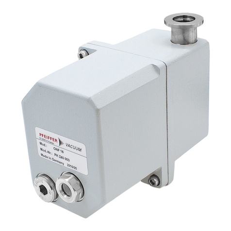
Pfeiffer Vacuum ONF 16 User manual

Translation of the original instructions
Operating Instructions
EN
PK 0213 BEN/I (1104)
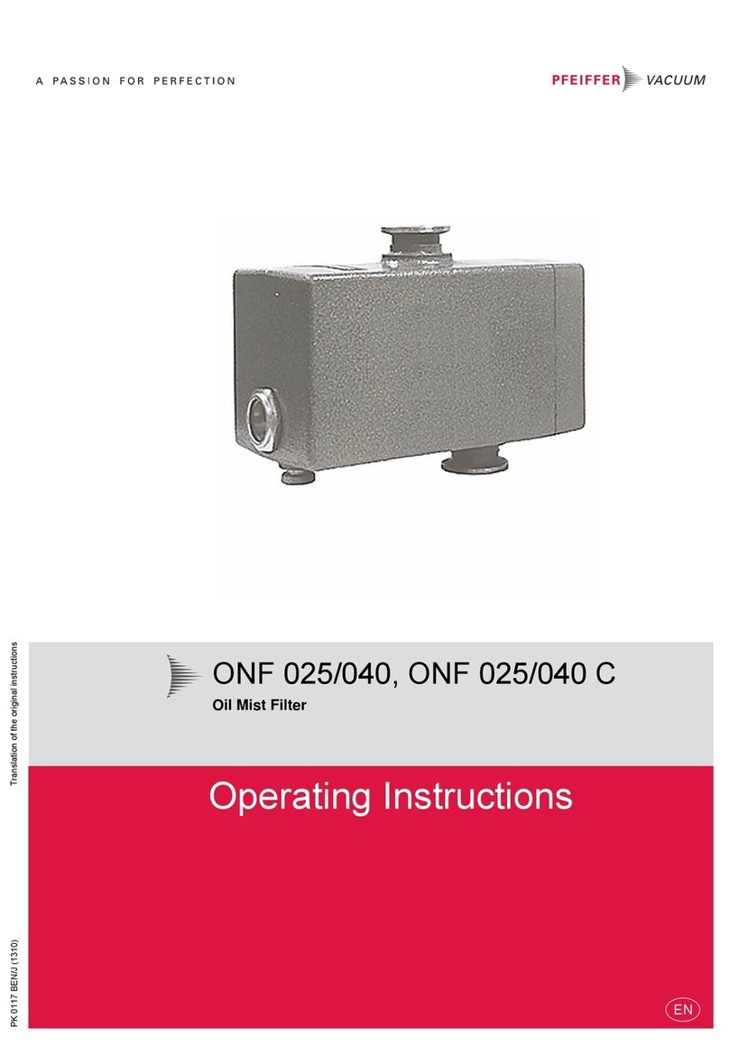
ONF 16, ONF 25/25L/25XL
Oil mist filter

2
Table of contents
Table of contents
1 About this manual. . . . . . . . . . . . . . . . . . . . . . . . . . . . . . . . . . . . . . . . . . . . . . . 3
1.1 Validity. . . . . . . . . . . . . . . . . . . . . . . . . . . . . . . . . . . . . . . . . . . . . . . . . . . . . 3
1.2 Conventions . . . . . . . . . . . . . . . . . . . . . . . . . . . . . . . . . . . . . . . . . . . . . . . . 3
2 Safety . . . . . . . . . . . . . . . . . . . . . . . . . . . . . . . . . . . . . . . . . . . . . . . . . . . . . . . . . 4
2.1 Safety precautions . . . . . . . . . . . . . . . . . . . . . . . . . . . . . . . . . . . . . . . . . . . 4
3 Transport and storage . . . . . . . . . . . . . . . . . . . . . . . . . . . . . . . . . . . . . . . . . . . . 5
3.1 Storage . . . . . . . . . . . . . . . . . . . . . . . . . . . . . . . . . . . . . . . . . . . . . . . . . . . . 5
4 Product description . . . . . . . . . . . . . . . . . . . . . . . . . . . . . . . . . . . . . . . . . . . . . . 5
4.1 Product identification . . . . . . . . . . . . . . . . . . . . . . . . . . . . . . . . . . . . . . . . . 5
4.2 Function . . . . . . . . . . . . . . . . . . . . . . . . . . . . . . . . . . . . . . . . . . . . . . . . . . . 6
5 Installation . . . . . . . . . . . . . . . . . . . . . . . . . . . . . . . . . . . . . . . . . . . . . . . . . . . . . 7
5.1 Assembly . . . . . . . . . . . . . . . . . . . . . . . . . . . . . . . . . . . . . . . . . . . . . . . . . . 7
5.2 Installing the operating fluid return line. . . . . . . . . . . . . . . . . . . . . . . . . . . . 8
6 Operation . . . . . . . . . . . . . . . . . . . . . . . . . . . . . . . . . . . . . . . . . . . . . . . . . . . . . . 9
7 Maintenance . . . . . . . . . . . . . . . . . . . . . . . . . . . . . . . . . . . . . . . . . . . . . . . . . . .10
7.1 Draining the operating fluid. . . . . . . . . . . . . . . . . . . . . . . . . . . . . . . . . . . . .10
7.2 Changing the filter element . . . . . . . . . . . . . . . . . . . . . . . . . . . . . . . . . . . .11
8 Service . . . . . . . . . . . . . . . . . . . . . . . . . . . . . . . . . . . . . . . . . . . . . . . . . . . . . . . 13
9 Accessories. . . . . . . . . . . . . . . . . . . . . . . . . . . . . . . . . . . . . . . . . . . . . . . . . . . . 14
10 Technical data . . . . . . . . . . . . . . . . . . . . . . . . . . . . . . . . . . . . . . . . . . . . . . . . . 14
10.1 Dimensions . . . . . . . . . . . . . . . . . . . . . . . . . . . . . . . . . . . . . . . . . . . . . . . . .15
11 Spare parts. . . . . . . . . . . . . . . . . . . . . . . . . . . . . . . . . . . . . . . . . . . . . . . . . . . . 16
11.1 Spare parts packages . . . . . . . . . . . . . . . . . . . . . . . . . . . . . . . . . . . . . . . . .16
12 Disposal . . . . . . . . . . . . . . . . . . . . . . . . . . . . . . . . . . . . . . . . . . . . . . . . . . . . . . 17
3
About this manual
1 About this manual
1.1 Validity
This operating manual is for customers of Pfeiffer Vacuum. It describes the func-
tioning of the designated product and provides the most important information for
safe use of the unit. The description follows applicable EU guidelines. All informa-
tion provided in this operating manual refer to the current state of the product's de-
velopment. The documentation remains valid as long as the customer does not
make any changes to the product.
Up-to-date operating instructions can also be downloaded from
www.pfeiffer-vacuum.net.
1.2 Conventions
Safety instructions The safety instructions in Pfeiffer Vacuum operating manuals are the result of risk
evaluations and hazard analyses and are oriented on international certification
standards as specified by UL, CSA, ANSI Z-535, SEMI S1, ISO 3864 and DIN 4844.
In this document, the following hazard levels and information are considered:
Pictogram definitions
DANGER
Immediate danger
Death or very severe injuries can occur.
WARNING
Possible danger
Injuries or severe property damages can occur.
CAUTION
Possible danger
Injuries or property damages can occur.
NOTE
Command or note
Command to perform an action or information about properties, the disregarding of
which may result in damage to the product.
Prohibition of an action or activity in connection with a
source of danger, the disregarding of which may result in
serious accidents.
Warning of a displayed source of danger in connection
with operation of the unit or equipment.
Command to perform an action or task associated with a
source of danger, the disregarding of which may result in
serious accidents.

4
Safety
Instructions in the
text
Work instruction: here you have to do something.
Abbreviations used ONF: Oil mist filter
ORF: Oil return device
2 Safety
2.1 Safety precautions
Before carrying out any work read and observe the operating and safety instruc-
tions of the pumping station and the individual components.
Connection to pumps or units which are not suitable for this purpose according
to their operating instructions.
Connection to units which have exposed voltage-carrying parts.
Observe the safety and accident prevention regulations.
Check regularly that all safety precautions are being complied with.
When returning the components to us please note the instructions in the Service
section.
The use of accessories or spare parts, which are not named in this manual.
NOTE
Duty to inform
Each person involved in the installation, operation or maintenance of the vacuum pump
must read and observe the safety-related parts of these operating instructions.
The operator is obligated to make operating personnel aware of dangers originating
from the vacuum pump, the pumped medium and the entire system.

5
Transport and storage
3 Transport and storage
3.1 Storage
The ONF should be stored dry and protected from moisture. The filter inserts can
absorb moisture, and the lubrication properties of the oil and hence the end pres-
sure can be negatively influenced in pumps with an oil return unit.
4 Product description
4.1 Product identification
To correctly identify the product when communicating with Pfeiffer Vacuum, al-
ways have the information from the rating plate available.
• Model and model number
• Date of manufacture
Fig. 1: Product identification on the rating plate (example)
Variants
Connection nominal diameter
Mod.:
Mod.-No.:
Made in Germany 2008/03
ONF 025
PK Z40 157
D-35614 Asslar
Type Connection nominal di-
ameter
intended for pump type
ONF 16 DN 16 ISO-KF UNO 2.5, UNO 5, DUO 2.5, DUO 5 M
ONF 25 DN 25 ISO-KF DUO 10 M, Penta 10
ONF 25L DN 25 ISO-KF UNO 30, DUO 20 M, Penta 20, TWIN 20-10
ONF 25XL DN 25 ISO-KF Penta 35

6
Product description
4.2 Function
The oil mist filter is mounted on the exhaust connection of rotary vane pumps. It
prevents air pollution from operating fluid mist that is ejected by the pump to a
greater or lesser degree depending on the operating pressure.
The filter inserts are installed in a housing made of corrosion-resistant aluminum
and consist of a cylindrical filter of glass polyester fleece. The filter inserts are
opened by an incorporated pressure relief valve when the contamination becomes
excessive so that the maximum working pressure of 1.5 bar (absolute) cannot be
exceeded. The collected operating fluid can be observed through a sightglass and
discharged with a drain screw.
Fig. 2: ONF 16/25/25 L
Operating fluid return
line
If the operating fluid accumulated in the ONF reaches a specified level, the operat-
ing fluid is channeled via differential pressure back into the rotary vane pump. Con-
densate concentrates underneath the oilpan and has to be drained when necessary
so as not to impair the operation of the pump
2 Housing ONF
4 Cover
10 Connection flange
(exhaust flange of rotary
vane pump)
12 Sight glass
30 O-ring
33 Operating fluid drain screw
2
33
12
30 10 4

7
Installation
5 Installation
5.1 Assembly
To install the ONF in a vacuum system, an ISO small flange or ISO clamp flanges
are provided on the input side and output side. The flanges are provided with pro-
tective caps when delivered to protect the seals.
If gases are pumped that may not enter the atmosphere, an exhaust line must be
connected to the exhaust flange.
If large amounts of vapour arise during operation, it is recommendable to install a
condensate separator between the rotary vane pump and ONF so that condensate
is removed in the KAS, and only oil mist enters the ONF.
Remove the protective caps from the connection flanges.
Place the ONF on the exhaust side of the rotary vane pump with the sightglass
facing downward, and fasten it with the clamping ring (accessory) or bracket
screws (accessory) if clamp flanges are used.
WARNING
Poisonous substances exit from the exhaust!
There is a poisoning hazard from discharged gases or vapours that can be hazardous
and/or polluting during use.
Install and run the exhaust line so that overpressure cannot build up inside it.
Follow the vacuum pump installation instructions in the respective operating instruc-
tions.
NOTE
Risk of the filter elements becoming blocked with resin!
When pumping gases and vapors with a tendency towards polymerization, the ONF fil-
ter elements can become resinified.
Observe the corresponding safety devices such as the saturation indicator or pres-
sure relief valve.

8
Installation
5.2 Installing the operating fluid return line
ONF 16/25/25 L Unscrew operating fluid drain screw 33.
Drain off operating fluid if so and fill in the pump.
Screw in hose nipple 241 inplace of the operating fluid drain screw; take care
with O-ring.
Remove gas ballast valve 42 from the pump and absorb the operating fluid un-
derneath.
Re-fit the gas ballast valve with intermediate flange 46 and screw tight with long-
er screws; take care with O-ring 148.
Screw fitting 240 into intermediate flange 46; pay attention to o-ring 138.
Fit operating fluid return hose 242 at both sides on the hose nipples and tighten
with hose clip 243 at the ONF side.
Tighten the union nut of the fitting 240.
Fig. 3: DUO Rotary vane pump with ONF and operating fluid return line
ONF 25 XL Unscrew operating fluid drain screw 33.
Drain off operating fluid if so and fill in the pump.
Screw in hose nipple 241 inplace of the operating fluid drain screw; take care
with O-ring.
Unscrew and remove the union nut of the screw fitting 77 and remove the seal-
ing plug 78.
Fit operating fluid return hose 242 at both sides on the hose nipples and tighten
with hose clip 243 at the ONF side.
Tighten the union nut of the screw fitting 77.
33 Operating fluid drain screw
42 Gas ballast valve
46 Intermediate flange
138 O-ring
145 O-ring
148 O-ring
198 Operating fluid filler
screw rotary vane pump
240 Fitting
241 Hose nipple
242 Operating fluid return
line
243 Hose clip
243
242
240(138)
46(148)
ONF
198
42
33 (241/145)

9
Operation
Fig. 4: PentaLine pump with ONF and Operating fluid return line
6 Operation
33 Operating fluid drain screw
77 Screw fitting
78 Sealing plug
145 O-ring
241 Hose nipple
242 Operating fluid return line
243 Hose clip
243
242
33
(241/145) 77
(78)
NOTE
Make sure that the return for the operating fluid works.
Operating fluid is only sucked in and returned from an operating pressure of < 100 mbar
and starting from a minimum quantity of operating fluid in the ONF.
Top up with operating fluid in order to ensure the return of operating fluid at the start
of the evacuation phase.
Long evacuation phases with a high intake pressure should always be followed by
operating phases with a lower operating pressure.
NOTE
Damage to the pump due to condensate in the operating fluid!
Returned condensate generated by vapors or by temperature differences between the
oil mist filter and pump impairs the quality of the operating fluid and negatively impacts
the pump's final vacuum.
Drain operating fluid built up with condensate in a time manner.

10
Maintenance
7 Maintenance
7.1 Draining the operating fluid
If the accumulated operating fluid in the ONF is above the top edge of the sight-
glass 12, the operating fluid must be drained.
The intervals at which the operating fluid is drained depends on the operating con-
ditions.
Screw out the operating fluid drain screw 33; pay attention to the O-ring 145.
Drain the operating fluid.
– If the drained operating fluid is free of foreign material, it can be fed back to
the rotary vane pump.
WARNING
Operating fluid may contain toxic substances from the pumped media!
Danger of poisoning from the emission of harmful substances from the operating fluid.
Wear suitable protective clothing and respirators.
Dispose of operating fluid according to the local regulations
WARNING
Toxic vapours!
Danger of poisoning when igniting and heating synthetic operating fluids (e.g. F4/F5)
above 300°C.
Observe the application instructions.
Do not allow operating fluid to make contact with tobacco products; observe safety
precautions when handling chemicals.

11
Maintenance
7.2 Changing the filter element
The filter insert must be exchanged or cleaned when the exhaust pressure increas-
es until the pressure relief valve opens inside the ONF and oil mist exits.
Dismantling
Fig. 5: ONF 16/25/25 L (with ONF 25 XL 8.1 is a part of 8)
Turn off the vacuum pump, vent to atmospheric pressure and allow to cool, if
necessary.
Unscrew operating fluid drain screw 33.
Drain off operating fluid.
Separate the operating fluid from the condensate.
– If the drained operating fluid is free of contamination, it can be fed back to the
rotary vane pump.
Remove ONF from the system and pour out the remaining operating fluid.
Unscrew and remove the screws 32 and carefully detach the housing 2 from the
cover 4;
– Caution! The parts are under preload.
Detach casing 2 and filter insert 8 and all other internally located parts from cov-
er 4; take care with o-rings 30 and 28 (not with ONF 25 XL).
Replace filter element 8; cleaning is not recommended in most cases.
Assembling is carried out in reverse order.
Dismantling the pressure relief valve
The pressure relief valve 8.1 at the ONF 25 XL is integrated in the filter insert 8 and
cannot be dismantled.
Loosen circlip 20 with pliers and dismantle washer 18, spring 16 and valve buffer
14 from valve housing 6.
Clean all parts and inspect for wear.
2Casing
4 Cover
6 Casing of pressure relief valve
8 Filter insert
11 D e f l e c t o r
12 Sight glass
14 Valve buffer
16 Pressure spring
18 Washer
20 Circlip
22 Compression spring
28 O-ring
30 O-ring
32 Screw
33 Operating fluid drain screw
4
30
33
12
222 20 16 628
8
11
18 14
32
28
8.1

12
Maintenance
Check the sealed surface of valve buffer 14; replace if necessary.
– When assembling lightly oil valve buffer and ensure the correct seating in the
valve housing 6.
Assembling Continue assembly by reversing the dismantling sequence, paying particular at-
tention to compliance with the following steps.
Put up cover 4, opening facing upwards.
Lightly oil O-ring 28 (seal at ONF 25XL).
When mounting casing 2 ensure the correct seating of the filter insert 8 and of
the pressure relief valve casing; in particular take care with regard to the position
of compression spring 22 and O-rings 28 and 30.

13
Service
8 Service
Pfeiffer Vacuum offers first-class service!
• Fast replacement with exchange products in mint condition
• Advice on the most cost-efficient and quickest solution
Detailed information, addresses and forms at: www.pfeiffer-vacuum.net (Service).
Maintenance and repairs in the Pfeiffer Vacuum ServiceCenter
The following steps are necessary to ensure a fast, smooth servicing process:
Download the forms "Service Request" and "Declaration on Contamination".1)
Fill out the "Service Request" form and send it by fax or e-mail to your
Pfeiffer Vacuum service address.
Include the confirmation on the service request from Pfeiffer Vacuum with your
shipment.
Fill out the declaration on contamination and include it in the shipment (re-
quired!).
Drain off operating fluid.
If possible, send pump or unit in the original packaging.
Sending of contaminated pumps or devices
No units will be accepted if they are contaminated with micro-biological, explosive
or radioactive substances. “Hazardous substances” are substances and com-
pounds in accordance with the hazardous goods directive (current version). If
pumps are contaminated or the declaration on contamination is missing, Pfeiffer
Vacuum performs decontamination at the shipper's expense.
Neutralise the pump by flushing it with nitrogen or dry air.
Close all openings airtight.
Seal the pump or unit in suitable protective film.
Return the pump/unit only in a suitable and sturdy transport container and send
it in while following applicable transport conditions.
Service orders
All service orders are carried out exclusively according to our repair conditions for
vacuum units and components.
1) Forms under www.pfeiffer-vacuum.net

14
Accessories
9 Accessories
10 Technical data
Oil return unit ONF 16 ONF 25 ONF 25 L ONF 25 XL
ORF from ONF 16 to
UNO 2.5, DUO 2.5, UNO 5
PK 194 315 -T
ORF from ONF 16 to
DUO 5 M
PK 196 172 -T
ORF from ONF 25 to
DUO 10 M
PK 196 172 -T
ORF from ONF 25 L to
DUO 20 M, TWIN 20-10
PK 196 172 -T
ORF from ONF 25 L to
UNO 30 M
PK 196 944 -T
ORF from ONF 25 to
Penta 10
PK 198 545 -T
ORF from ONF 25 L to
Penta 20
PK 198 545 -T
ORF from ONF 25 XL to
Penta 35
PK 198 545 -T
Parameter ONF 16 ONF 25 ONF 25 L ONF 25 XL
Degree of separation 99.98 % 99.98 % 99.98 % 99.98 %
Flange (in) DN 16 ISO-KF DN 25 ISO-KF DN 25 ISO-KF DN 25 ISO-KF
Flange (out) DN 16 ISO-KF DN 25 ISO-KF DN 25 ISO-KF DN 25 ISO-KF
For pumping speed 1,25-5 m3/h 10 m3/h 30 m3/h 34 m3/h
Capacity 0.15 l 0.15 l 0.25 l 0.35 l
Weight 1.35 kg 1.4 kg 1.6 kg 1.9 kg

15
Technical data
10.1 Dimensions
Fig. 6: ONF 16/25/25 L
Fig. 7: ONF 25 XL
Dimensions ONF 16 ONF 25 ONF 25 L
A 142 mm 147 mm 218 mm
B 80 mm 80 mm 80 mm
C 120 mm 132 mm 134 mm
D 127 mm 127 mm 182 mm
E 16 mm 16 mm 25 mm
F 105 mm 105 mm 105 mm
G 17 mm 23 mm 27 mm
H 48 mm 48 mm - mm
F
C
E
B
H
G
A
D
284
26
23
25
25
134
80
105
DN 25 ISO-KF
DN 25 ISO-KF
11 33

16
Spare parts
11 Spare parts
The spare parts packages listed here are only applicable for standard models.
Please state all information on the rating plate when ordering spare parts. Other
spare parts than those described in this manual must not be used without the
agreement of Pfeiffer Vacuum.
11.1 Spare parts packages
ONF 16/25/25 L
Fig. 8: ONF 16/25/25 L
Spare parts pack-
age
Model No. Consisting of
Maintenance kit ONF 16 PK E37 001 -T 8, 28, 30
ONF 25 PK E37 001 -T 8, 28, 30
PK E37 003 -T 8, 28, 30ONF 25 L
Overhaul kit ONF 25 XL PK E37 100 -T 8, 30
ONF 16 PK E37 002 -T 8, 12, 14, 16, 18, 20, 22, 28, 30, 33
ONF 25 PK E37 002 -T 8, 12, 14, 16, 18, 20, 22, 28, 30, 33
ONF 25 L PK E37 004 -T 8, 12, 14, 16, 18, 20, 22, 28, 30, 33
ONF 25 XL PK E37 101 -T 8, 12, 22, 24, 30, 33
4
30
33
12
222 20 16 628
8
11
18 14
32
28
8.1

17
Disposal
ONF 025 XL
Fig. 9: ONF 025 XL
12 Disposal
Products or parts thereof (mechanical and electrical components, operating fluids,
etc.) may cause environmental burden.
Safely dispose of the materials according to the locally applicable regulations.
11
10
2
32
33
30
8
4
22
12
24
This manual suits for next models
3
Table of contents
Other Pfeiffer Vacuum Water Filtration System manuals

Pfeiffer Vacuum
Pfeiffer Vacuum OME 16 M/ATEX User manual

Pfeiffer Vacuum
Pfeiffer Vacuum ONF 16 M User manual

Pfeiffer Vacuum
Pfeiffer Vacuum ONF 025 User manual

Pfeiffer Vacuum
Pfeiffer Vacuum OME 16 ATEX User manual

Pfeiffer Vacuum
Pfeiffer Vacuum SAS 16 User manual

Pfeiffer Vacuum
Pfeiffer Vacuum OME 40S User manual

Pfeiffer Vacuum
Pfeiffer Vacuum OME 40 M User manual