CATALOG
Chapter1 Safety and notes.........................................................................................................................................................3
1-1 Installation notes .........................................................................................................................................................3
1-2Attention points of operation and using ......................................................................................................................3
1-3 Storage notes...............................................................................................................................................................3
1-4 Dismantling notes........................................................................................................................................................ 3
1-5 High-voltage warning.................................................................................................................................................. 4
Chapter2 whole machine standard and terminal functions........................................................................................................4
2-1 Basic standard .............................................................................................................................................................4
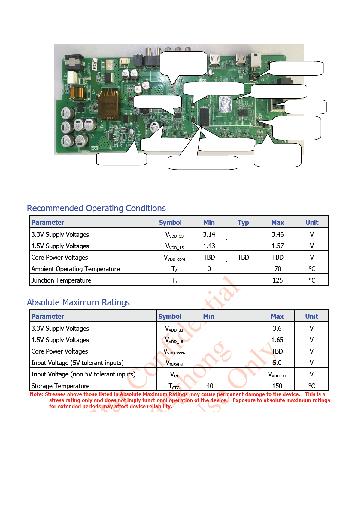
2-2 Introduction of terminals(practicality photos).............................................................................................................5
Chapter3 Main chip functions and the introductions of power supply......................................................................................5
3-1 Main IC and functions of HLS78D-I .......................................................................................................................... 5
3-2 Pin function description of HLS78D-I chip and description of power supply............................................................ 6
3-2-1 MSD6486 recommended operating power conditions....................................................................................6
3-2-2 Pin function of R842....................................................................................................................................... 7
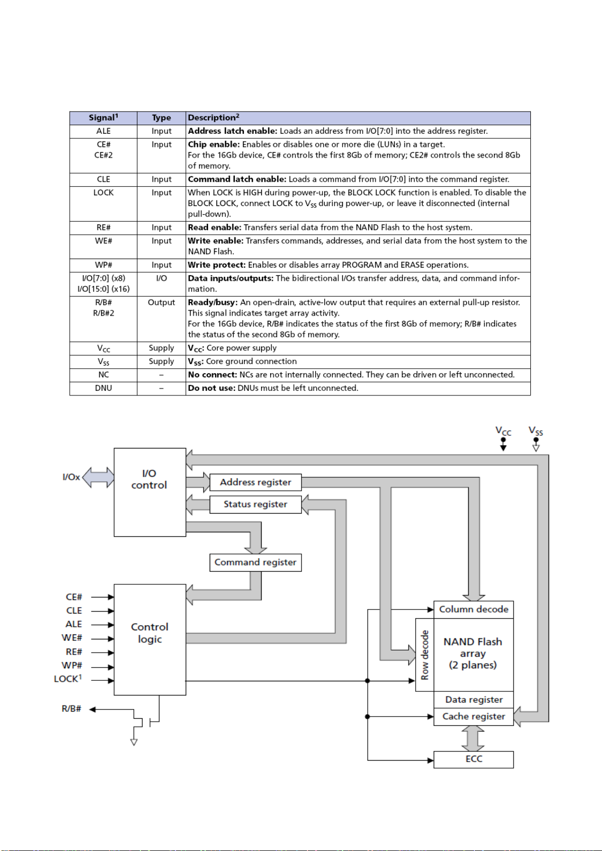
3-2-3 MT29F4G08ABADAWP:D NAND Flash/4Gbit brief introduction: ..............................................................8
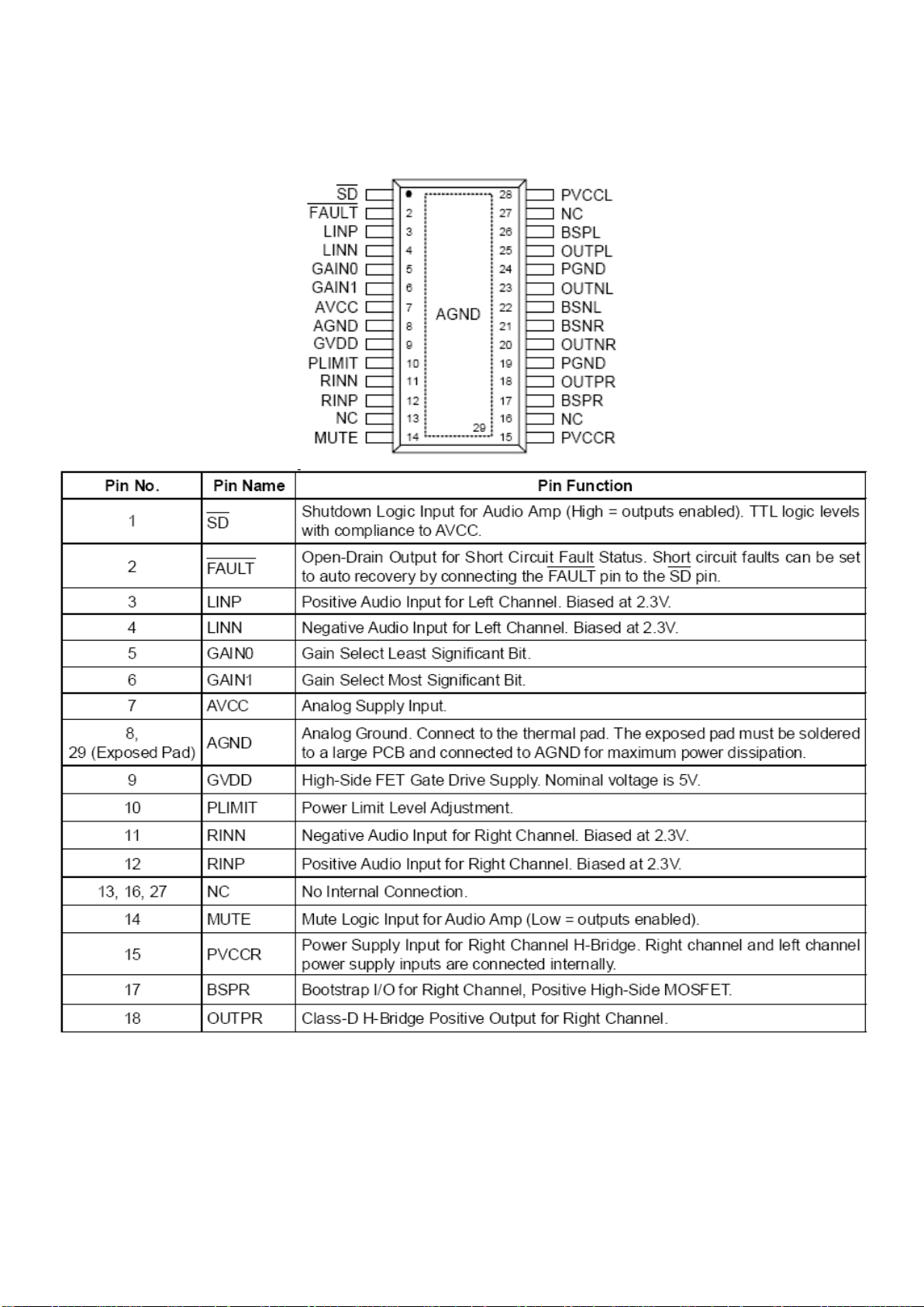
3-2-4 RT9108 brief introduction:...............................................................................................................................9
3-2-5 AMS1117-3.3 brief introduction:................................................................................................................... 10
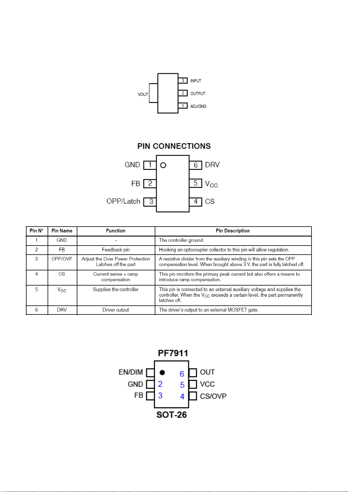
3-2-6 NCP1251A Current-Mode PWMController for Off-linePower Supplies brief introduction:........................ 10
3-2-7 PF7911 High Voltage BoostController brief introduction: ............................................................................10
3-2-8 TPS563201 brief introduction:....................................................................................................................... 11
3-2-9 SY8088 brief introduction: ............................................................................................................................ 11
3-2-10 MP2225GJ brief introduction:.....................................................................................................................12
3-3 Brief introduction of power supply...........................................................................................................................13
Chapter4 MSD6486 Power Block Diagram, main board power supply systems, main board interface definition and the
waveform of key points...........................................................................................................................................................13
4-1 MSD6486 Power Block Diagram..............................................................................................................................14
4-2 Power supply system................................................................................................................................................. 14
4-2-1 Pin voltage of the voltage adjuster on the main board...................................................................................14
4-2-2 Interface definition.........................................................................................................................................15
Chapter5 Software upgrade instructions.................................................................................................................................. 15
Software upgrade method:Use a U disk including the upgrade program directly upgrade ..........................................15
Chapter6: Classical accident maintenance procedures and examples ..................................................................................... 16
6-1 The thinking of don’t boot......................................................................................................................................... 16
6-2 Common problems for your reference ...................................................................................................................... 16
6-3 Trouble shooting........................................................................................................................................................17
Chapter7 Factory mode parameter setting instructions and notes...........................................................................................24
7-1 Enter into the factory mode.......................................................................................................................................24
7-2 The list of factory mode as follow:(only for reference).................................................................................24
Chapter8 Instructions of HLS78D-I module Circuit Schematic Diagram............................................................................... 26
Appendix:Circuit Schematic Diagram..................................................................................................................................27