PHOTOFACT*
Folder
PHILCO
MODELS
52-T18O2,
52-T1821,
52-T1822,
52-T1845,52-T212O,
52-T215O-W,
52-T2151,
-L,
52-T2252,
53-T1824,53-T1825,
53-T1826,
53-T1852,
53-T2152
(Code
124)
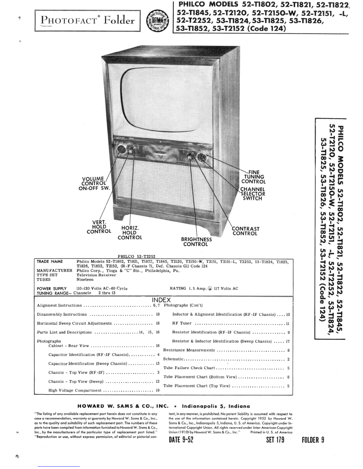
VOLUME
CONTROL'
ON-OFF
SW.
VERT.
HOLD
HORIZ
CONTROL
VIOLD
CONTROL
FINE
TUNING
CONTROL
CHANNEL
SELECTOR
SWITCH
CONTRAST
CONTROL
BRIGHTNESS
CONTROL
PHILCO
52-T2252
TRADE
NAME
Philco
Models
52-T1802,
T1821,T1822,T1845,T2120,T2150-W,T2151,
T2151-L,
T2252,53-T1824,
T1825,
T1826,T1852,T2152,(R-F
Chassis
71,
Def.
Chassis
Gl)
Code
124
MANUFACTURER
Philco
Corp.,
Tioga
&"C"Sts.,
Philadelphia,
Pa.
TYPE
SET
Television
Receiver
TUBES
Nineteen
POWERSUPPLY
110-120
Volts
AC-60
Cycle
TUNING
RANGE-Channels
2
thru
13
RATING
1.5
Amp.
®
117
Volts
AC
INDEX
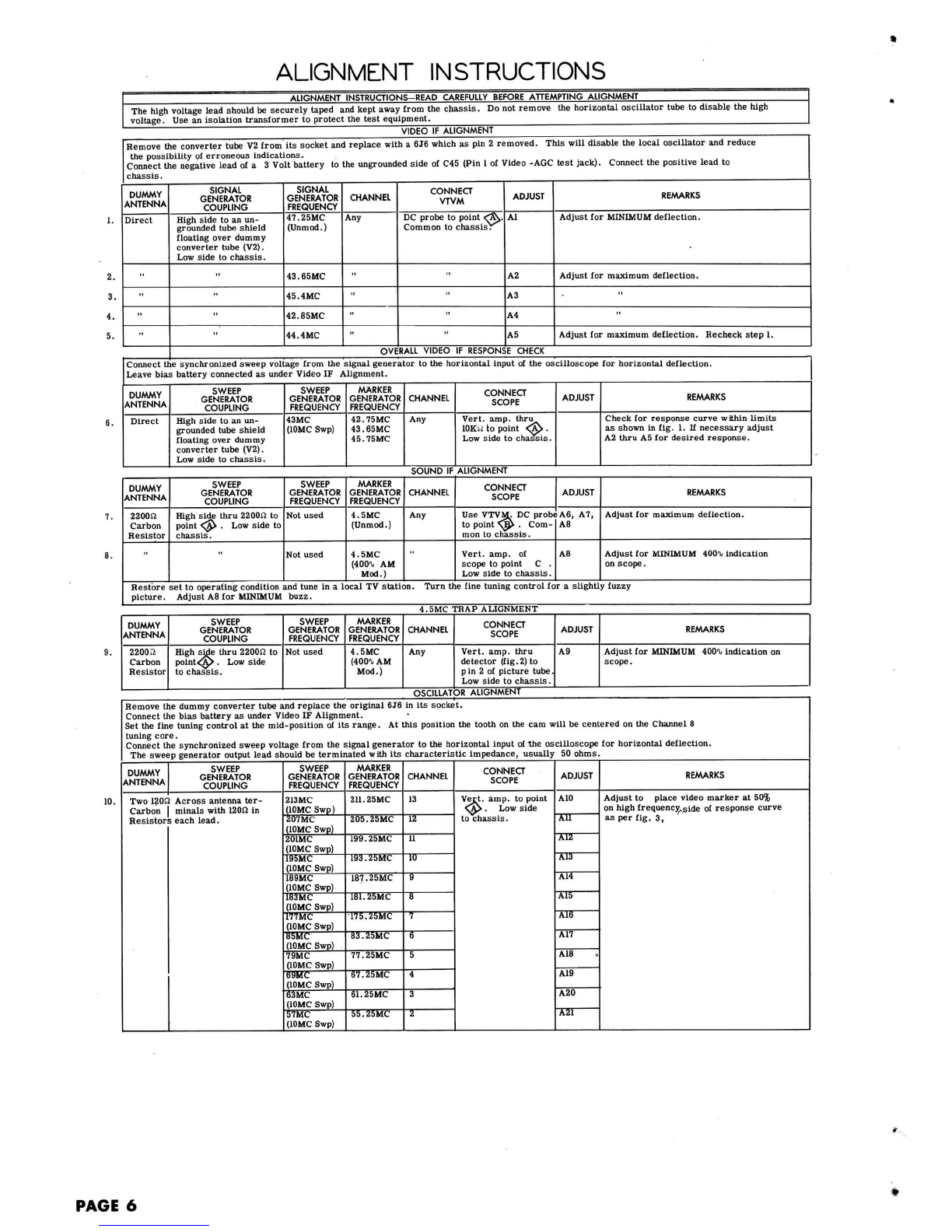
Alignment
Instructions
6,7
Photographs
(Con't)
DisassemblyInstructions
18
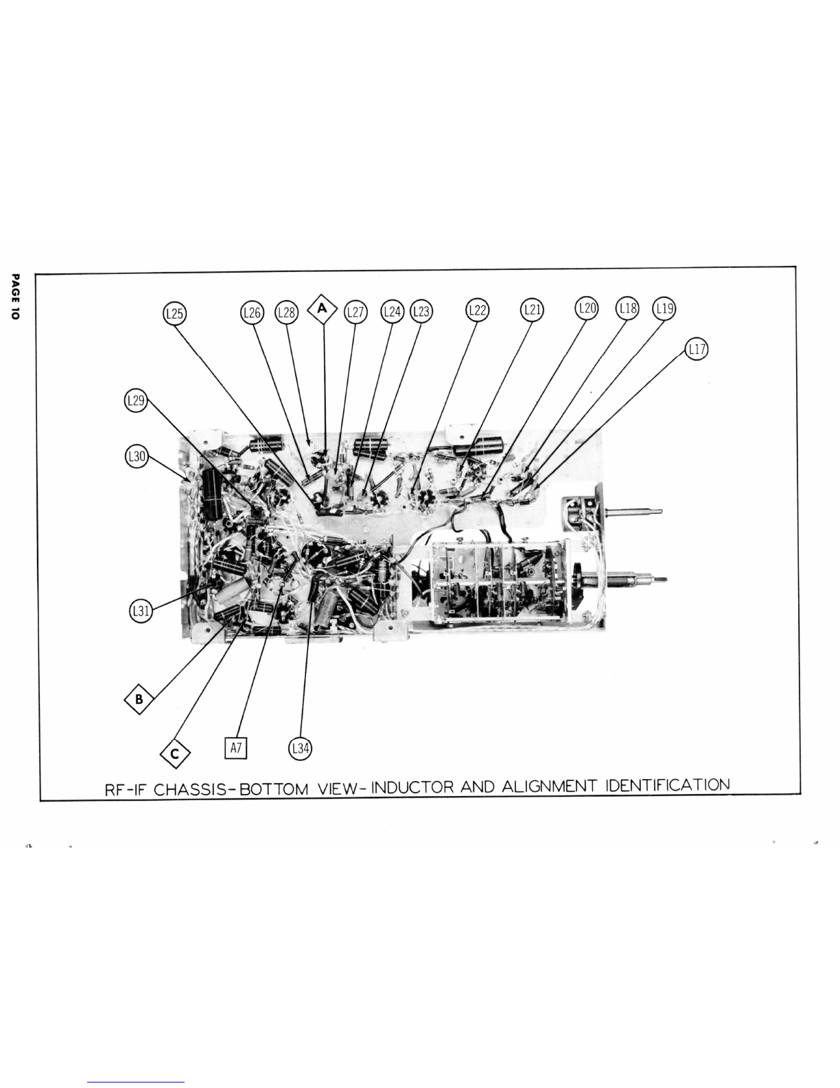
Inductor
&
Alignment
Identification
(RF-IF
Chassis)
....
10
HorizontalSweep
Circuit
Adjustments
18RF
Tuner
11
Parts
List
and
Descriptions
14,15,16
Resistor
Identification(RF-IF
Chassis)
9
Photographs
Cabinet
-
Rear
View
18
Resistor
&
InductorIdentification(Sweep
Chassis)
.....
17
Capacitor
Identification(RF-IF
Chassis)
4
Capacitor
Identification
(Sweep
Chassis)
13
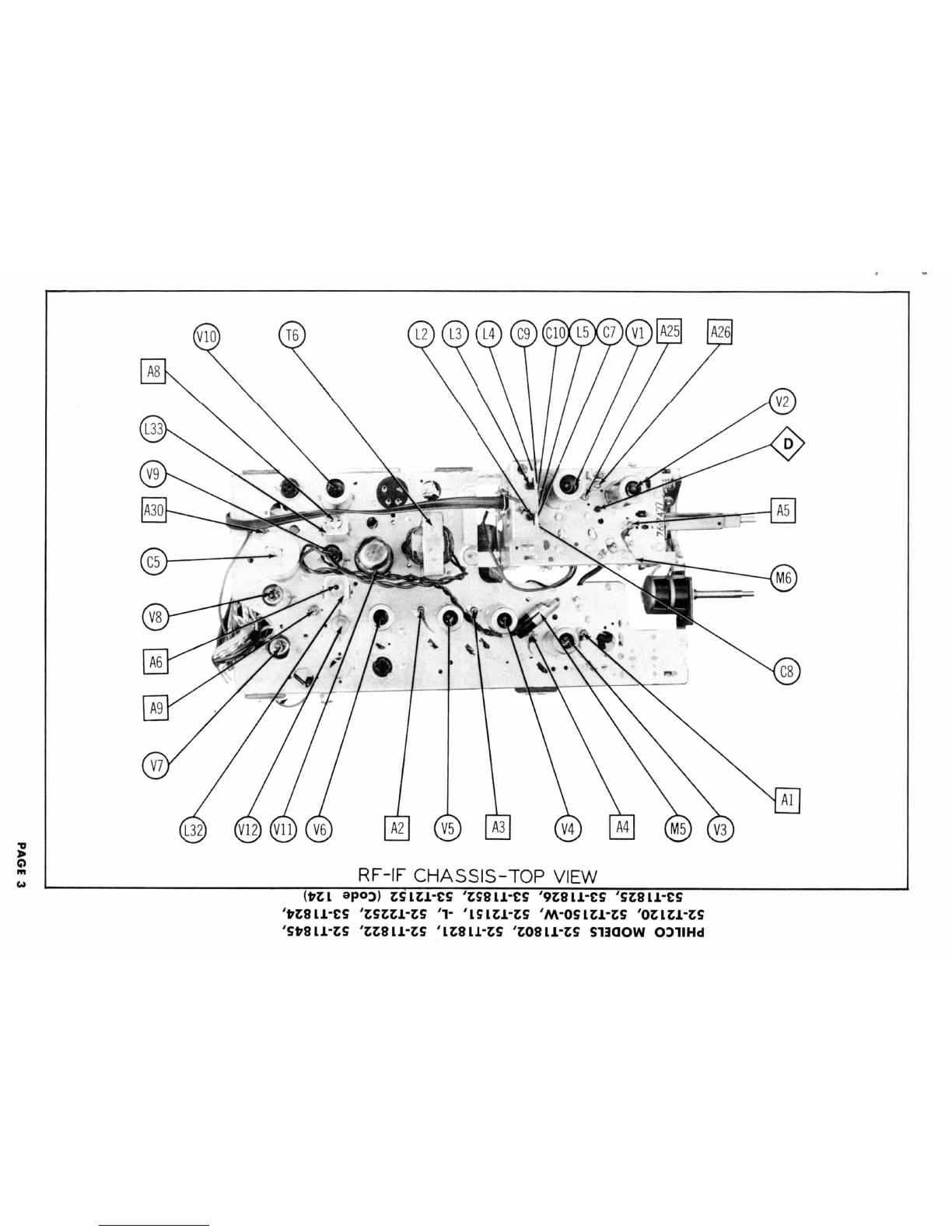
Chassis
- Top
View
(HF-IF)
3
Chassis
- Top
View(Sweep)
12
High
VoltageCompartment
19
Resistance
Measurements
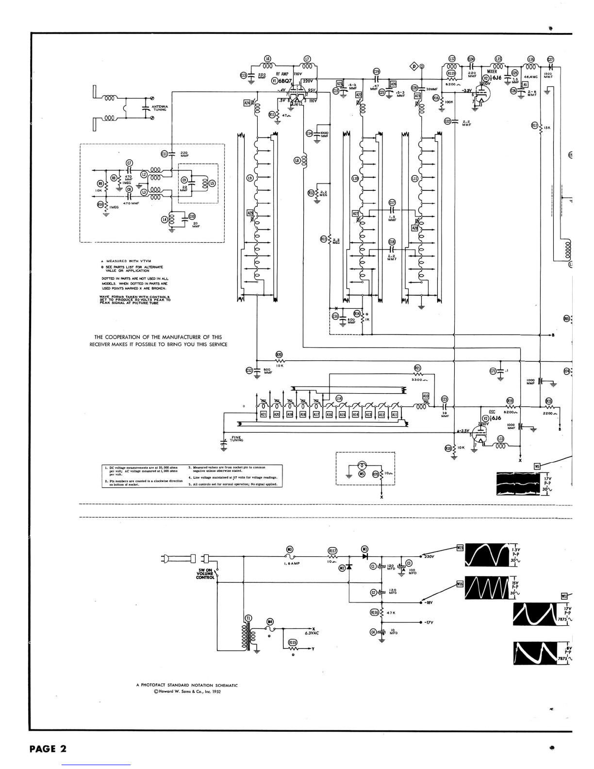
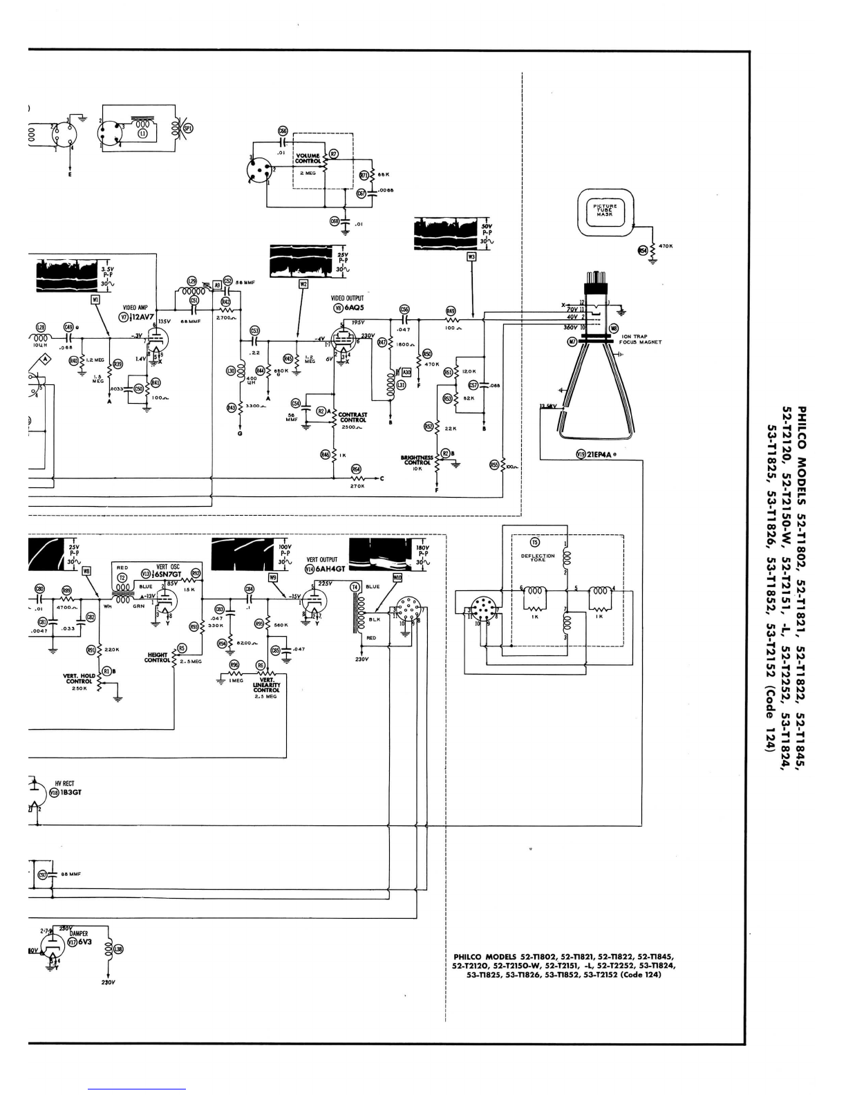
Schematic
2
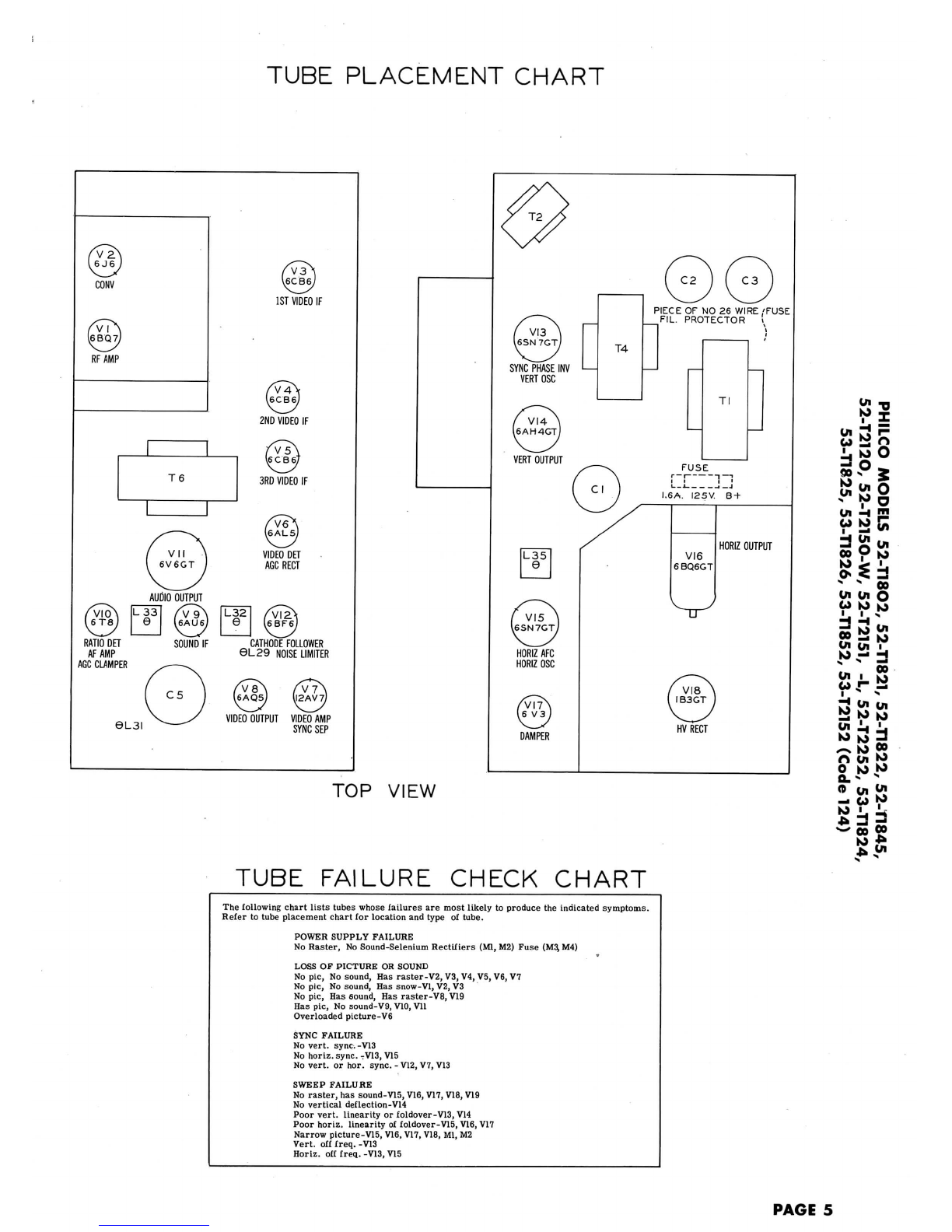
Tube
Failure
Check
Chart
. 5
Tube
Placement
Chart(Bottom
View)
,
TubePlacement
Chart
(Top
View)
..
5
01
oo
01
Ugu.
co
p
w
.
s
>
00
Cn
4/i
O
O
K>
M
33s
0
g.
<o
in
10
HOWARD
W.
SAMS
&
CO.,INC.
•
Indianapolis
5,
Indiana
"Thelisting
ofany
available
replacement
part
hereindoes
not
constitute
inany
case
a
recommendation,warranty
or
guaranty
by
Howard
W.
Sams
&
Co.,Inc.,
as
tothe
quality
and
suitability
of
such
replacement
part.
The
numbers
of
these
partshavebeen
compiled
from
information
furnished
to
Howard
W.
Sams
&
Co.,
Inc.,
bythe
manufacturers
ofthe
particular
type
of
replacement
part
listed."
"Reproduction
or
use,without
express
permission,
of
editorial
or
pictorial
con-
tent,
in
any
manner,
is
prohibited.
No
patent
liability
is
assumed
with
respect
to
the
useofthe
informationcontainedherein.Copyright
1952
by
Howard
W.
Sams
&
Co.,Inc.,
Indianapolis
5,
Indiana,
U.S.of
America.Copyrightunder
In-
ternational
Copyright
Union.
All
rights reservedunderInter-American Copyright
Union
(1910)
by
Howard
W.
Sams
&
Co.,Inc."Printed
inU.S.of
America
DATE
9-52
SET
179
FOLDER
9