CN
LU
PHOTO
FACT8
Folder
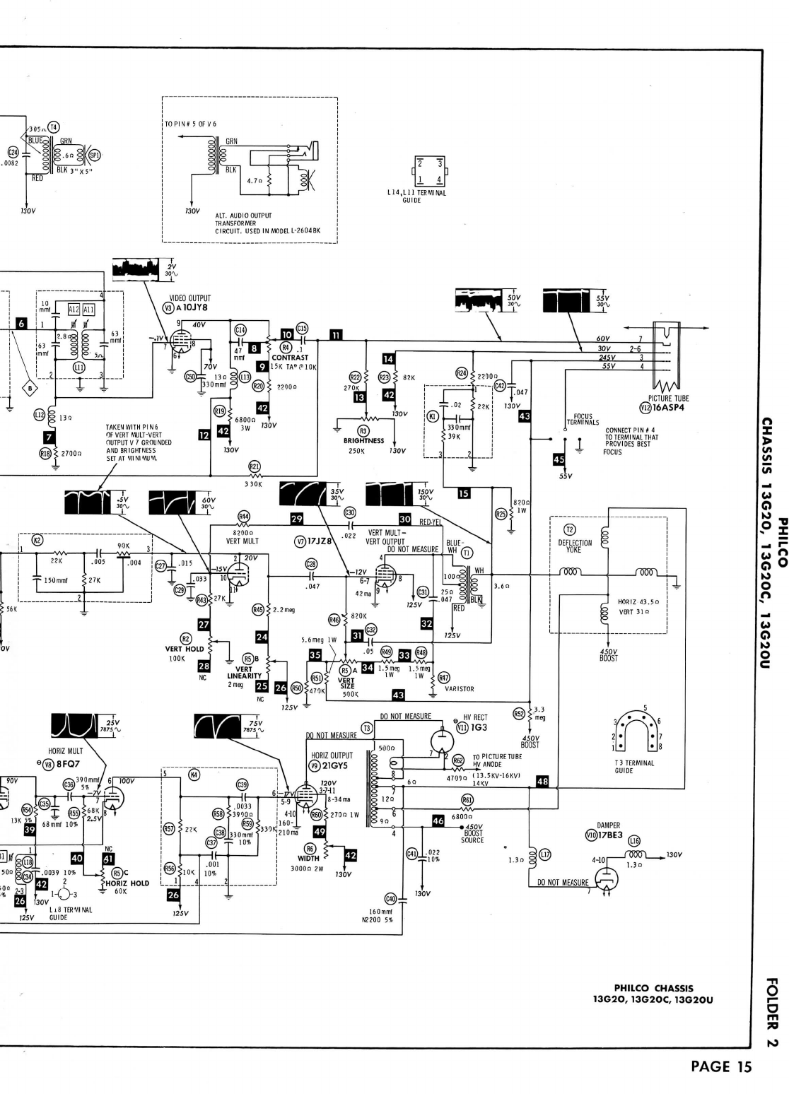
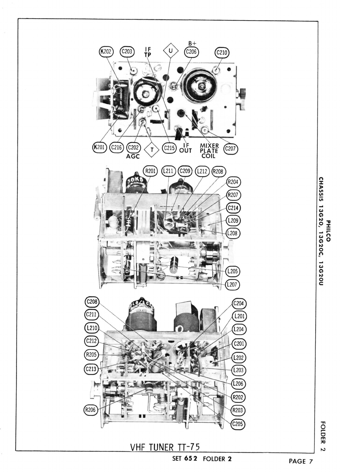
PHILCO
CHASSIS
13G20,
13G20C,
13G2OU
O
w»
(5
82
oo
u
co
ii
o
o
MODEL
L2602BR
CAUTION
ONE
SIDE
OF AC
LINE
CONNECTED
TO
CHASSIS
TRADE
NAME
MANUFACTURER
TYPE
SET
TUBES
POWER
SUPPLY
TUNING
RANGE
PHILCO
Models
Chassis
L2600BU,
L2602BR,
L2604BK
13G20
L2600CBU,
L2602CBR,L2604CBK
13G20C
UL2600BU,
UL2602BR,
UL2604BK
13G20U
Philco
Corp.,
a
Subsidiary
of
Ford
Motor
Co.,
Tioga
&
"C"
Streets,
Philadelphia,Pennsylvania
Television
Receiver
VHF
-
Fourteen,
UHF
-
Fifteen
110-120
Volts
AC,60
Cycles
RATING
110
Watts,
1.3
Amp.
S)
117
Volts
AC
Channels
2
thru
13
VHF,
14
thru
83
UHF,Video
IF45.
75MC,Sound
IF41.
25MC
(Intercarrier)
SERVICING
INTHE
FIELD
SAFETY
GLASS
The
safely
glass
isan
integralpart
ofthe
picturetube.
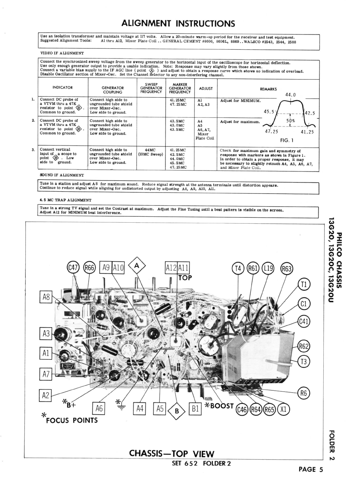
FUSE
OR
FUSE
DEVICE
by
the
propersetting
of
the
Horizontal
Stabilizer
Coil Slug
(Bl).
(See
"Chassis
- Top
View"
Photo.)
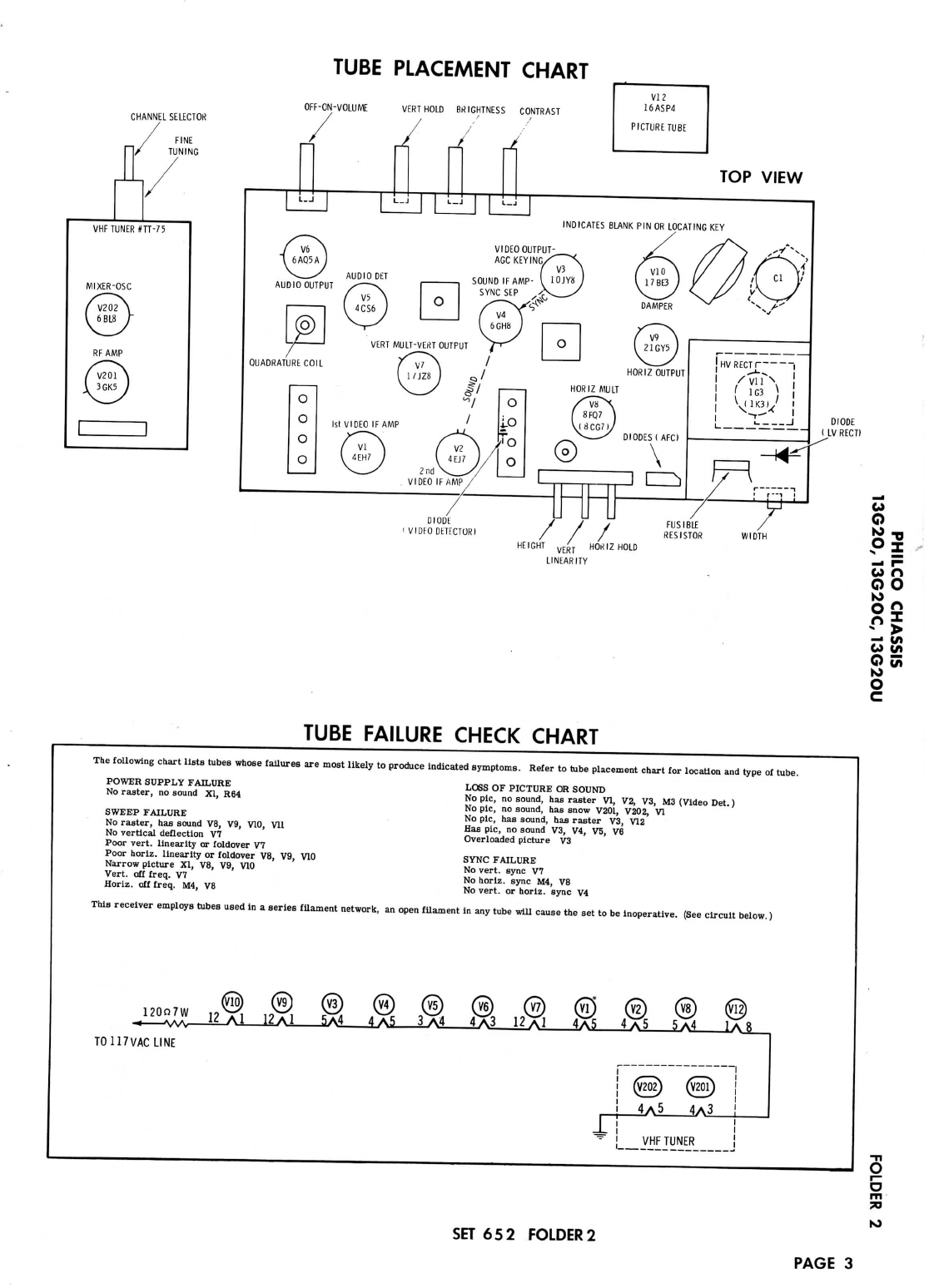
WIDTH
A
5.6S2
fusible
resistor
is
used
forlow
voltagepowersup-
ply
protection.(Forlocation,
see
"Cabinet
-
Rear
View".)
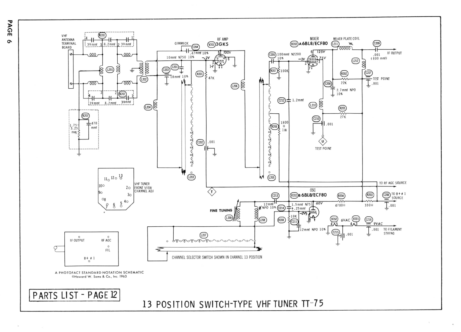
VHF
OSCILLATOR
ADJUSTMENT
Set
fine
tuning
atthe
center
ofits
range
and
adjust
osc.
slug
(one
for
each
channel)
for
best
sound
and
picture.
AGC
No
provision
is
made
to
vary
theAGCon
thisreceiver.
HORIZONTAL
OSCILLATOR
FIELD
ADJUSTMENT
Coarse
adjustment
ofthe
horizontal
hold
is
accomplished
The
width
maybe
varied
bya
Width
control.
(See"Tube
PlacementChart"
for
location.)
FOCUS
The
focus
maybe
varied
by
connecting
the
lead
from
pin4
of
the
picture
tube
to
variousvoltagepoints.(Forlocation,
see
"Chassis
- Top
View"
Photo.)
CENTERING
Centering
is
accomplished
by2
magnetic
rings
located
on
yoke
rear
cover.
CJ
O
co
n
GO
2*
o
to
=3
o
tn
10
HOWARD
W.
SAMS
&
CO.,
INC.Indianapolis
6,
Indiana
The
listing
ofany
availablereplacement
part
herein
does
not
constitute
inany
case
a
recommendation,warranty
or
guaranty
by
Howard
W.
Sams
&
Co.,Inc.,
astothe
quality
and
suitability
of
suchreplacement
part.
The
numbers
of
these
parts
havebeencompiled
from
informationfurnished
to
Howard
W.
Sams
&
Co.,Inc.,
by the
manufacturers
of the
particulartype
of
replacement
part
listed.
MA
208
Reproduction
or
use,
withoutexpresspermission,
of
editorial
or
pictorial
^
content,
inany
manner,
is
prohibited.
No
patentliability
is
assumed
with
JQ
respect
totheuseofthe
informationcontained
herein.
©
1963Howard
W.
..
Sams
&
Co.,Inc.,Indianapolis
6,
Indiana.
Printed
inU.S.of
America
DATE
9-63
SET
652
FOLDER
2