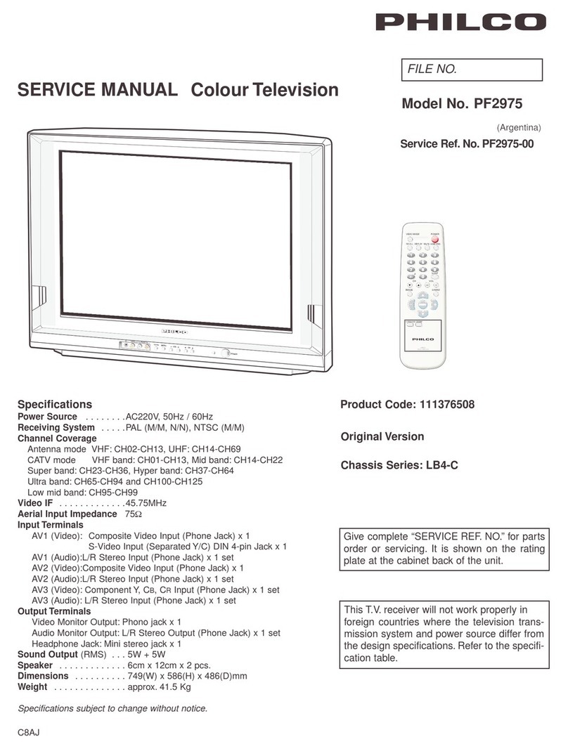
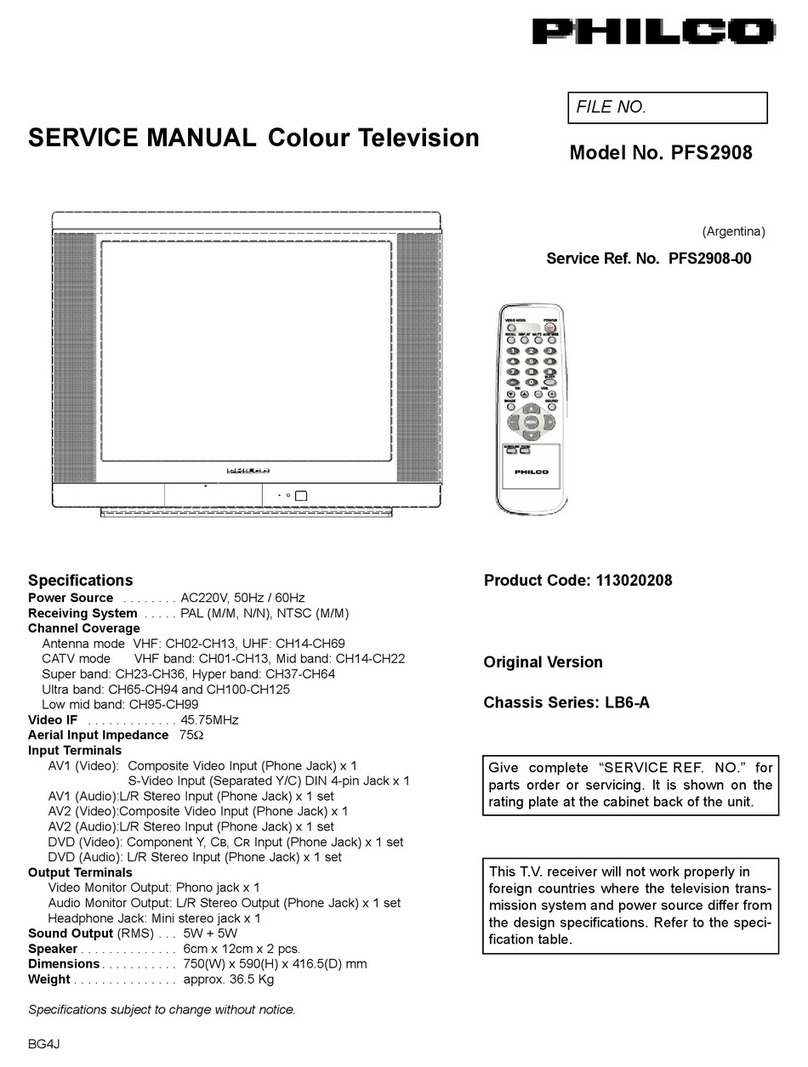
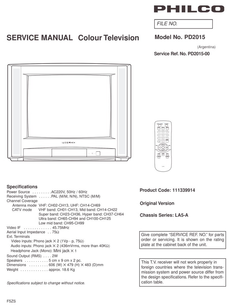
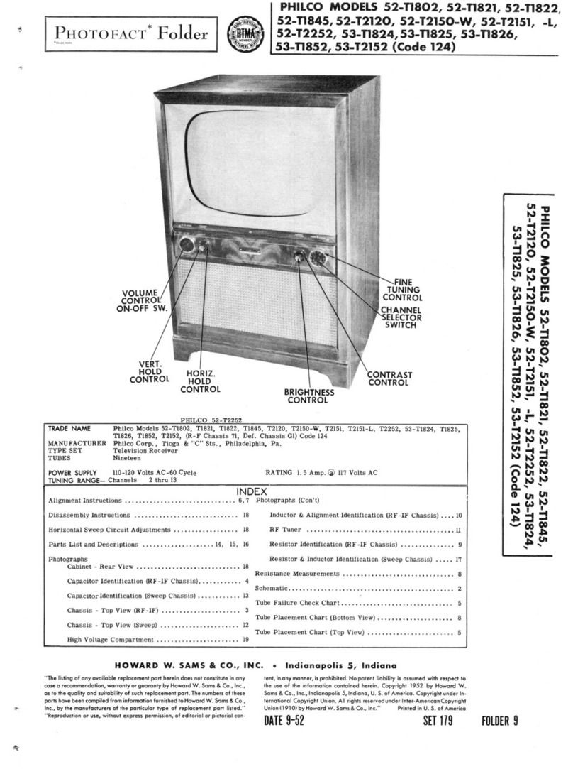
Philco PF2118 User manual

SERVICE MANUAL Colour Television
Product Code:
Original Version
Chassis Series: LA7-A
BF4J
FILE NO.
Model No. PF2118
Service Ref. No.
(Argentina)
Give complete “SERVICE REF. NO.” for
parts order or servicing. It is shown on the
rating plate at the cabinet back of the unit.
This T.V. receiver will not work properly in
foreign countries where the television trans-
mission system and power source differ from
the design specifications. Refer to the speci-
fication table.
Specifications
Power Source . . . . . . . . . AC220V, 50Hz / 60Hz
Receiving System . . . . . . PAL (M/M, N/N), NTSC (M/M)
Channel Coverage
Antenna mode VHF: CH02-CH13, UHF: CH14-CH69
CATV mode VHF band: CH01-CH13, Mid band: CH14-CH22
Super band: CH23-CH36, Hyper band: CH37-CH64
Ultra band: CH65-CH94 and CH100-CH125
Low mid band: CH95-CH99
Aerial Input Impedance . . 75Ω
Input Terminals
AV1 (Video): Phono jack ✕1
AV1 (Audio): Phono jack (R/L) ✕1 set
AV2 (Video): Phono jack ✕1
AV2 (Audio): Phono jack (R/L) ✕1 set
Output Terminals
Video Monitor Output: Phono jack ✕1
Audio Monitor Output: Phono jack (R/L) ✕1
Headphone Jack: Mini stereo jack ✕1
Sound Output (RMS) . . . . 3W + 3W
Speakers . . . . . . . . . . . 5cm x 9cm x 2 pcs.
Dimensions . . . . . . . . . 596(W) X 493(H) X462(D) mm
Weight . . . . . . . . . . . . . approx. 20.5 Kg
Specifications subject to change without notice.
映像メディア(事)デザイン部
JXMRR
CH
-
VOL+
MENU
VIDEO
LAUDIOR
AV2
IN
POWER

Contents
-2-
SafetyNotice ........................................................................... 2
ChassisBlockDiagram ................................................................. 3-4
ICBlockDiagrams..................................................................... 5-8
ServiceAdjustments................................................................... 9-17
PurityandConvergenceAdjustment....................................................... 18
CabinetPartsList....................................................................... 19
ChassisElectricalPartsList............................................................ 20-26
Safety Notice
SAFETY PRECAUTIONS
1: An isolation transformer should be connected in the
power line between the receiver and the AC line
when a service is performed on the primary of the
converter transformer of the set.
2: Comply with all caution and safety-related notes
provided on the cabinet back, inside the cabinet, on
the chassis or the picture tube.
3: When replacing a chassis in the cabinet, always
be certain that all the protective devices are
installed properly, such as, control knobs, adjust-
ment covers or shields, barriers, isolation resistor-
capacitor networks etc.. Before returning any
television to the customer, the service techni-
cian must be sure that it is completely safe
to operate without danger of electrical shock.
X-RADIATION PRECAUTION
The primary source of X-RADIATION in television receiver is the picture tube. The picture tube is specially con-
structed to limit X-RADIATION emissions. For continued X-RADIATION protection, the replacement tube must
be the same type as the original including suffix letter. Excessive high voltage may produce potentially hazard-
ous X - RADIATION. To avoid such hazards, the high voltage must be maintained within specified limit. Refer
to this service manual, high voltage adjustment for specific high voltage limit. If high voltage exceeds specified
limits, take necessary corrective action. Carefully follow the instructions for + B1 volt power supply adjustment,
and high voltage check to maintain the high voltage within the specified limits.
PRODUCT SAFETY NOTICE
Product safety should be considered when a component replacement is made in any area of a receiver.
Components indicated by mark in the parts list and the schematic diagram designate components in which
safety can be of special significance. It is particularly recommended that only parts designated on the parts list
in this manual be used for component replacement designated by mark . No deviations from resistance
wattage or voltage ratings may be made for replacement items designated by mark .

Chassis Block Diagrams
-3-
AUDIOPW
AUDIOPW
AERIAL
VIDEO
VERT-OUT
SAW FILTER (LA76931) HORIZ-DRIVE HORIZ-OUT
SPEAK(L)
SPEAK(R)
AUDIO-OUT
AV1 / AV2 AUDIO INPUT
AUDIO OUTPUT
FBT PULSE
FBT IN
POWER
CRT DRIVE
MAIN SIGNAL PROCESSING CIRCUIT

Chassis Block Diagrams
-4-
IC 601 POWER SUPPLY IC (STRW6753)
FUNCTIONAL BLOCK DIAGRAM

IC Block Diagrams
-5-
IC201 < IF/Video/Chroma/Def./CPU > LA76931

IC Block Diagrams
-6-
S ample a ppl ication ci r cuits
S ample a ppl ication ci r cuits2
L A 78040B /040/041/045
Vref
+V cc
IN
1 2 3 4 5 6 7
L A 78040B /040/041/045
Vr ef
+V cc
IN
1 2 3 4 5 6 7
-V cc
123 4 5 6 7
G ND
Ver.O U T P UT
OU T PU T S T AG E V cc
N ON I N V.I N P UT
IN V E R T I N G I N P UT
V c
c
P U M P U P O UT
P ump
U
p
+
-
AMP
T her mal
P r otection
L A78040B /040/041/045
5V
+V cc(24V)
IN
1 2 3 4 5 6 7
10K 33K
10K
11K
4.7u
1000u1.0
330
1.0 0.1u
100u
100u
10K
10K
1u
IC501<Vertical.Output> LA78040
!
7]\X]\IUXTQNQMZ
7]\X]\IUXTQNQMZ
1VX]\IUXTQNQMZ
1VX]\IUXTQNQMZ
>KKOZW]VL[PWZ\QVOXZW\MK\QWVKQZK]Q\
4WIL[PWZ\QVOXZW\MK\QWVKQZK]Q\
<PMZUITXZW\MK\QWVKQZK]Q\
16
16
7=<
7=<
8?:
/6,
7=<
7=<
ʪ
:Q%
Sʪ
:QXXTM
.QT\MZ
>^^
;\IVLJa
8:-
/6,
5=<-
:Q%
S
IC001<AUDIO AMP> LA42032

IC Block Diagrams
-7-
LA72703 BTSC Decoder - Reference Apprication -
10 11 12
Slave Address = 80h ( 1000 000* ) :Pin8=OPEN/GND
Slave Address = 84h ( 1000 010* ) :Pin8=H
Vcc 5V
+
98
65 7
4
21 3
21
2324 22 15 14 13
161719
20 18
MATRIX
MODE
OUT
REGULATOR
+ ++
+
++
+
+
+
4.5M
BPF
LPF
SIF DEMOD
SAP BPF
SAP
DEMOD
L-R
DEMOD ST/SAP
SW
LPF
-6dB
PILOT
CANCELLER
STEREO
PLL
PILOT
DET
PILOT
LEVEL DET
IIC
DECODE
SYSTEM
CONTROL
Offset
Cancell
dbx processor
SAP
DET
4u7 4u7 22u 4u7
OUT(L) OUT(R)
MODE
Monitor
2u2
1u
1u
0.1?
1u
4k7
MUTE
L+R L-R/SAP
ST
SAP
Address
Control
GND
MUTE
Wide RMS DET
Spectral DET
Spectral In
Offset Cancel
0.1u
0.1u
4u7
1u to
0.33u
SIF SIGNAL
from Tuner
Address
Control IIC
DATA
IIC
CLOCK
2u2 22u
Spectral RMS
DET
100u
0.1u
47u
+
10u
+
10u
33n 33n
+
1u
+
560k
LPF
IC3401 LA72703 STEREO DECODER

-8-
IC Block Diagrams
IC3402 AUDIO SIGNAL PROCESSOR
R2A15908SP
INR2
INR1
INL1
INL2
INL5
IGOUTL
VOLINL
VOLINR
BASSL1
INL3
INL4
IGOUTR
BASSR2
ROUT
LOUT
AGND
SDA
SCL
DGND
BASSL2
TRER
VCC
REFIN
BASSR1
INR4
INR3
INR5 28
27
26
25
24
23
22
21
20
19
1
2
3
4
5
6
7
8
9
10
18
17
11
12
Mode selector
Surround
REF
Input
selector
13
14
16
15
Tone control
Rch Bass/Treble
Volume
0~+20dB
/2dB step
Input
selector
0~-87dB,-∞
MCU
I/F
Input gain
control
mute
mute
Tone control
Lch Bass/Treble
Volume
0~-87dB,-∞
0~+20dB
/2dB step
Mono
/Stereo
TREL

-9--9-
Service Adjustments
MENU
MENU
S1.11100101 S2.11110011
ADDRESS DATA
01 RFAGC 21
Item No. Item Data value
General
This set has an On-screen Service Menu system included in the CPU that allows remote operation for most of the
service adjustments.
2. Service Adjustments:
Press the CHANNEL UP or CHANNEL DOWN
button on the remote control handset to select the
desired service menu item you want to adjust.
Use the VOLUME + or
-
to adjust the data. The + or
-
button will increase or decrease the data
sequentially.
3. Exit from the Service Menu
Press the MENU button to turn off the Service Menu
display.
The data which is set in the service mode is stored
into the memory IC automatically.
[ Service Mode Display ]
Service Adjustment-1
1. Enter the Service Menu
While pressing the MENU button on the television, press the Number Key 2 on the remote control unit.
The Service Menu now appear.
IC802 (EEPROM) Replacement
When IC802 (EEPROM) is replaced, IC801 (CPU) will automatically write the initial reference data into IC802 for basic TV operation.
However, the bus data should be checked and some bus data should be set up before attempting the service adjustments. (See
pages 9 ~ 10 for detailed information.)
映像メディア(事)デザイン部
JXMRR
映像メディア(事)デザイン部
JXMRR
VOLUME +
VOLUME
-
CHANNEL UP
CHANNEL DOWN

-10--10-
Service Adjustments
On-screen Service Menu
Following table shows the initial values which have been stored in the CPU ROM, and items for the service adjustments.
When IC802 (EEPROM) is replaced, check the bus data to confirm they are the same as below. The shaded menu should be
checked and be set up or readjusted according to the procedures described in the following pages.
Initial Setup Data marked with an * should be changed from Initial Value Data.
1 RFAGC 21 00~63 RFAGCadjustment
2 H-PHA 08 00~31 H-PHASEadjustment(50Hz)
3 V-DC40 00~63 V-POSITIONadjustment(50Hz)
4 V-SIZ 37 00~127 V-SIZEadjustment(50Hz)
5 V-SCO 12 00~31 Vertical-Scompensation(50Hz)
6 V-LIN11 00~31 Verticallinearityadjustment(50Hz)
7 H-P60 +4 -16~+15 DifferencevalueofH-PHASEadjustment(60Hz)
8 V-P60 -3 -32~+31 DifferencevalueofV-POSITIONadjustment(60Hz)
9 V-S60-4 -64~+63 DifferencevalueofV-SIZEadjustment(60Hz)
10 VSC60 0 -16~+15 DifferencevalueofVertical-"S"compensation(60Hz)
11 VLI60+1 -16~+15 DifferencevalueofVerticallinearityadjustment(60Hz)
12 OSDHP 35 01~255 OSDhorizontalremarkposition
13 OSDC05 00~07 OSDContrast
14 V-SCP 03 0~7 V-SIZECOMP
15 VSHIFT 10 0~15 V.SHIFT
16 SBIAS70 00~127 SubBiasadjustment
17 RBIAS00 00~255 RedBiasadjustment
18 GBIAS 00 00~255 GreenBiasadjustment
19 BBIAS00 00~255 BlueBiasadjustment
20 RDRIV 64 00~127 RedDriveadjustment
21 GDRIV 08 00~15 GreenDriveadjustment
22 BDRIV 64 00~127 BlueDriveadjustment
23 Whitebalance(alateralline)
24 DRV BrightandDarkofWhitebalanceadjustment
25 B-YD11 00~15 B-YDCLevel
26 R-YD11 00~15 R-YDCLevel
27 B-YDN 0 -16~+15 DifferencevalueofNTSCB-YDCLevel
28 R-YDN 0 -16~+15 DifferencevalueofNTSCR-YDCLevel
29 G-YA00 00~01 G-YAngle
30 RBGB10 00~15 R-Y/B-YGainBalance
31 RBAG08 00~15 R-Y/B-Y Angle
32 G-YAN 00 00~01 NTSC G-Y Angle
33 RBGBN +7 -8~+7 DifferencevalueofNTSCR-Y/B-YGainBalance
34 RBAGN +4 -8~+7 DifferencevalueofNTSCR-Y/B-YAngle
35 COGV 03 00~03 CoringGain
36 BLKS 00 00~03 Blk.str.start(W/Defeat)
37 BLKG00 00~03 Blk.STR.gain
38 BRTA 00 00~01 Brt.Abl.Def
39 BRST00 00~01 Mid.Stp.Def
40 BRTH00 00~07 Bright.Abl.Threshold
41 WPL 00 00~03 WPLOpe.Point(W/Defeat)
No Item Initial value Range Description
-11--11-
Service Adjustments
42 YGAM 00 00~03 YGammaStart
43 PRES 02 00~03 AVModePreShootadj
44 OVERS 03 00~03 AVModeOverShootadj
45 RFCO+1 -2~+1 DifferencevalueofRFCoringGain
46 PRESN 00 00~03 RFModePreShootadj
47 OVERSN 03 00~03 RFModeOverShootadj
48 TINT -8 -16~+15 Tint
49 SHRF+5 -16~+15 DifferencevalueofRFsharpness
50 RFCOL +5 -16~+15 DifferencevalueofTVcolor
51 TEXC+1 -4~+3 OSD TEXT Contrast
52 AUFL00 00~01 Auto.Flesh
53 COOP07 00~07 ColorKilleropt.
54 VCOFRQ 00 0~255VCOFreq
55 DEEM 00 00~01 De-emphasisTC
56 V-LVL05 00~07 VideoLvel
57 STRAP 04 00~07 S.TrapAdjust
58 IFOM-S 00 00~01 OVERMODURATIONSW
59 IFMN-S 00 00~01 AUDIOMONITORSW、MONITORORFM
60 IFTRPS 01 00~01 ICbuilt-inSIF TRAP SW ON-OFF
61 OVMLVL 08 00~15 OVERMODLEVEL
62 VBSW 00 00~01 VBLKSW
63 FBTS 00 00~01 FBPBLK.SW
64 HBLKL 05 00~07 H-BlankingControlLeft
65 HBLKR 03 00~07 H-BlankingControlRight
66 AFCRF 00 00~01 Adj.ofAFCGain&gate(RF)
67 VSURF 00 00~01AdjustmentofVerticalSync.SeparationSensitivity(RF)
68 CDMRF 00 00~07 VertialCountDownLoopAdjustment(RF)
69 AFCAV 01 00~01 Adj.ofAFCGain&gate(AV)
70 VSUAV 00 00~01AdjustmentofVerticalSync.SeparationSensitivity(AV)
71 CDMAV 00 00~07 VertialCountDownLoopAdjustment(AV)
72 HLK-T 01 0,1 Hlock,Vdet(RF)
73 HLK-V 01 0,1 Hlock,Vdet(AV)
74 VCOADJ 06 00~07 C.VCOAdjust(NTSC、PAL-Ncorresponding)
75 GRAY 00 0,1 GRAYMODE
76 CROSS 00 0~3 CROSSB/W
77 HL-TON 00 0~3 HALFTONELEVEL
78 AVNCON 64 00~127 AVCONTRAST(NoSignalinAV)
79 AVNBRI 64 00~127 BRIGHT(NoSignalinAV)
80 POMT 12 00~127 PowerMuteTime
81 CHMT 05 00~31 ChMuteTime
82 SYST03 00~255 System
83 RELAY 125 00~255 Powerrelayontime(8msec)
84 CCD 33 1~63CAPTIONHorizontalRemarkPosition
85 AVTVTM 01 0~255FEATHERMENUAV/TVCHAGNE
86 FM-G00 00~01 FMGain
87 CTRAP 04 0~7 C.TRAPADJUST
No Item Initial value Range Description
-12-
Service Adjustments
88 CBPF 00 0~3 C.BPFADJUST
89 C-KILL 00 0~1 C_KILLON
90 G-YAMP 08 0~15 G-YAMP
91 B-YDPM 0 -16~+15 DifferencevalueofPALMB-YDCLevel
92 R-YDPM 0 -16~+15 DifferencevalueofPALMR-YDCLevel
93 YTH 00 0~3 YTH
94 YGAIN 00 0~3 YGain
95 RWIDTH 00 0~3 RWidth
96 ROFSET 00 0~3 ROffset
97 BWIDTH 00 0~3 BWidth
98 BOFSET 00 0~3 BOffset
99 RGBTMP 01 0~1 RGBTEMPSW
100 VCOPLM 04 00~07 C.VCOAdjust(PAL-Mcorresponding)
101 OSDPIC 14 0~127 OSDMENUPICTURESH-POSITION
102 OPTPOW 00 0~1 LASTPOWERSTATUSOPTION
103 OPTAVN 00 0~1 1AVOR2AVSYSTEMOPTION
104 VER VERSIONANDDATE
No Item Initial value Range Description

-13-
Service Adjustments
Important Notice:
Do not attempt to adjust service adjustments not listed on below otherwise it may cause loss of performance and for
correct operation.
Item 01 [RFAGC] AGC
NOTE: Do not attempt this adjustment with weak signal.
1. Tune the receiver to most clearest (or strongest) VHF
station in your area. Set the brightness and contrast
controls to maximum. Set the colour control to mini-
mum.
2. Select Item No. 01 [RFAGC] in the service mode.
3. Change value until the snow noise just disappears.
4. Exit from the service mode.
1. Receive a monochrome circular pattern.
2. Set the brightness and contrast to normal.
3. Select Item No. 02 [H-PHA] in the service mode.
4. Change value to be optimum horizontal centre posi-
tion.
5. Exit from the service mode.
1. Receive a monochrome circular pattern.
2. Set the brightness and contrast to maximum.
3. Select Item No. 15 [VSHIFT] in the service mode.
4. Change value to be optimum vertical centre position.
5. Exit from the service mode.
Item 04 [V-SIZ] VERTICAL SIZE
1. Receive a monochrome circular pattern.
2. Set the brightness and contrast to maximum.
3. Select Item No. 04 [V-SIZ] in the service mode.
4. Change value to be optimum vertical size.
5. Exit from the service mode.
1. Receive a monochrome circular pattern.
2. Set the brightness and contrast to normal.
3. Select Item No. 12 [OSDHP] in the service mode.
4. Change value to be proper OSD position.
5. Exit from the service mode.
1. Tune receiver to a caption channel.
2. Check that CAPTION position is in the horizontal
center of the screen. If CAPTION center is too right or
left, perform steps 3-5. (See figure below.)
3. Select Item No. 85 [CCD] in the service mode.
4. Adjust data with + or - key for proper horizontal center.
5. Exit from the service mode.
Vertical centre
Vertical size
XXX XXXX XXXX XXX
AB
Caption H-position Adj.
A=B
Item 02 [H-PHA] HORIZONTAL CENTRE
Item 12 [OSDHP] OSD POSITION
Horizontal centre
Item 15 [VSHIFT] VERTICAL CENTRE
±Item 84 [CCD] CAPTION H-POSITION ADJ.

映像メディア(事)デザイン部
JXMRR
-14-
Items 16-23 GREY SCALE
(1) Receive a monochrome circular pattern.
(2) Set the brightness and colour to normal, contrast to maximum.
(3) Enter to the service mode.
(4) Set each value of Item-16 SBIAS, 17 RBIAS, 18 GBIAS, 19 BBIAS mode to 00. Set each value of Item-20 RDRIV
mode to 64, 21 GDRIV to 08.
(5) Select Item-23 mode to be one horizontal scanning line and turn the screen volume on the FBT to obtain just vis-
ible one coloured line.
(6) Press the 1 (Red Bias +), 4 (Red Bias
-
), 2 (Green Bias +), 5 (Green Bias
-
), 3 (Blue Bias +) or 6 (Blue Bias
-
)
button to adjust the brightness of each colour until a dim white line produced. Please see the control button alloca-
tions in this mode.
(7) Select Item-24 DRV mode to enter the white balance adjusting mode.
(8) Press the 7 (Red Drive +), RECALL (Red Drive
-
), 8 (Green Drive +) or 0 (Green Drive
-
) button, 9 (Blue
Drive +) or SLEEP TIMER (Blue Drive
-
) alternately to produce normal black and white picture.
(9) Exit from the service mode.
(10) Check for proper grey scale tracking at all brightness levels.
NOTE: If the grey scale adjustment is made after picture tube replacement, check the high voltage.
Service Adjustments
Red Bias
-
Red Bias +
Green Bias
-
Blue Bias +
Red Drive +
Green Drive
-
Blue Drive +
Green Bias +
Blue Bias
-
Press the MENU button to exit from
service mode
Red Drive
-
Green Drive +
Blue Drive
-
MAIN BOARD
HH
H
H
HH
HH
H
HH
HH
HH
HH
H
HH
HH
HH HH
H
HH
H
HH
H
H
HH
HH
HH
H
HH
HH
HH
H
HH
HH
HH
H
HH
H
HH
HH
HH
H
H
HH
HH H
H
H
H
HH
H
H
H
1LG4B10Y02900_Y
1LG4B10Y0290A_Y
*** ???
*** ???
??? ***
PS601A
F601
T4AL250V
D1911
RCA-2
AV_IN
5
10 15
20 25 30
404550
60
LA7A.CHASSIS
LA7A.CHASSIS
55
1LG4B10Y0290B_ Y
*** ???
KG-2 KG-3
1
5
KX
TP-A
TP-E
X801
SW1901
SW601
33
64
1
32
IC201
IC001
C3401
C1101
C1001
C101
C001
A101
X202
SW1902
E
Q1902
1
4
5 8
IC802
C1902
C1102
C1002
C202
C002
SW1903
R103
C1103
C003
SW1904
C1004
C204
C104
SW1905
C805
C106
C006
C007
C3408
C008 C009
C210
C010
X211
C1111
C011
C3412
C1112
C012
C3413
C1913
C215
C122
C1023
C225
C226
C231
C233
C244
C245
C246
C247
C1903
C358
X161
C863
C291
C893
C299
K1002
A1901
KE-1
KE-2
VA601
RL601
C601
D605
D606
D607
C607
D608
C608
L611
C611
C614
C617
C618
C619
L621
F601A
D621
F601B
C624
C625
C639
L661
C622
E
Q622
E
Q631
C631
E
Q632
C632
C661
IC601
K1003
KDY-1
KDY-3
KDY-4
KDY-5
C503
R505
C505
C506
E
Q431
L431
L432
C432
C433
C434
C436
C437
D438
D439
C449
C424A
C355
Q461
E
Q462
C468
C469
C470
C471
C475
R477
R488
C491
C486
T431
C467
C616
E
Q436
E
Q437
Q432A
Q432
Q461A
R435
R602
L601
D485
R477A
C463
C431
IC601A
C423
C420
L442
C424
C425
C465
C441
C442
D1901
1
16
98
T611
D681
T471
D616
C606
PS601
JP487
JC31
JC32
JC35
JE52
JF25
JB41
JB51
JB52
JH35
JH38
JH39
JF46
JP1101
JE35
JG36
JE56
JB42
JB43
JF33
JH34
L205
JD30
JP1102
JP1105
JE55
JE61
JE62
JB11
JH11
L201
JF57
JF61
JF62
JP603
JE23
JE51
JD21
JH21
JF34
JF35
JF37
JF38
L204
JF52
JF58
JH10
JH13
JF411
JP1103
JA31
JG11
JE21
JA41
JG21
JG22
JG23
JE31
JG33
JG34
JE54
L1901
JF13
JH12
JH22
JH32
JH310
JP1106
JP486
JP488
JF24
JH23
JF54
JF56
JP001
R437
R230
R432
R839
R840
R844
R697
R108
R612
R621
R431
R820
R821
R822
R636
R1921
R1924
R469
R470
R471
R473
R474
R280
R510
R357
R592
R594
D593
D1915
D1916
D609
D421
D249
D466
D470
D476
D102
D103
D352
D353
D003
D611
D613
D614
D461
D462
D465
D467
D468
D486
D699
D357
R698
R018
R019
R211
R020
R021
R023
R613
R423
R618
R619
R620
R631
R423A
R484
R485
R696
R355
R115
R601
R1112
R1114
R433
R628
R629
R632
R661
R475
D002
D612
L202
JG35
L101
R228
R424
JD31
JC62
JC61
IC501
K1004
R502
R503
C504
R504
C004
C605
R509
C510
C613
C3414
C3416
C3418
C623
R1314
C3436
C3439
C3424
KDY-6
X3401
L3401
D501
JP502
JP503
C3403
C507
C3409
C509
C3410
R513
C1024
C1025
IC631
C3443
C3445
R3451
R3452
C3452
C3453
R3455
R3457
24
1
13
12
IC3401
C3420
C3421
C3422
C3423
R462
R508
C511
C512
JE22
R512
JF21
JF22
JE42
JF40
JF41
R434
R1900
R177
JH311
JH41
C612
C615
JG44
JH42
JH33
C005
D622
C662
JF310
R025
JF42
R637
JF47
JF43
R3437
R3436
JH43
JE36
JF31
R830
R421
JP646
R818
D615
JC33
C628
C629
C627
JF48
R009
JE33
JE34
1
5
KP
1
3
KQ
JF49
L462
IC501A
C609
D103A
JH37
JF36
JF311
R213
JG46
R3434
JH36
R026
JF312
R644
R645
C646
R647
R648
E
IC662
D624
R635
JE37
R609
R610
R514
R515
R516
R616
R617
R638
R441
R442
R445
R662
R663
R481
R290
R506
R646
JE58
JE57
JD33
JE38
JE41
JE11
1
KR
IC202
IC681
JA42
JD11
JH312
JH30
JC34
R641
JF410
D469
JD32
R517
JE20
JF30
JE53
JE40
JF412
JA43
JP501
D631
L441
R639
IC001A
JF314
R427
JF315
JD62
L461
L631
JF39
R352
C620
TP-B
JF23
R1061
34
2
1
D610
1
3
KL
E
Q711A
K701
K7M
L702A
Q701
Q711
Q721
E
Q701A
E
Q721A
K7D1
K701M
R700
C700
C751
C741
C710
JS741
R741
R732
R716M
R717M
R715
R716
R717
L700
L701
L703
L711
L721
R703
R751
D742
D741
C731
1
5
K7P
1
3
K7Q
R723
R713
R704
R714
R724
A30C5
T471H11
T471H7
Q432HC
L441H3
IC501AH2
Q432AH3
T471H2
C609H1
R602H3
T471H10
SW601H3
T611H5
Q461AH2
SW601H4
R435H1
Q461AH1
L442H2
IC601AH1
L601H3
SW601H1
Q432HB
L601H4
IC501AH4
T471H5
R435H2
PS601H3
SW601H2
T471H8
C609H2
Q432HE
IC601AH2
Q432AH2
R602H2
PS601H1
IC501AH1
T471H1
IC601AH3
IC501AH3
Q432AH4
L441H2
T611H2
R602H1
T471H4
L442H1
T611AH16
L441H1
L601H2
Q432AH1
PS601H2
L601H1
A30C5
DIP
SCREEN VR
(Under side)

映像メディア(事)デザイン部
JXMRR
Service Adjustments
-15-
Service Adjustment-2 (MTS Adjustment)
1. Enter the Service Menu
While pressing the MENU button on the televi-
sion, press the Number Key 3 on the remote control
unit. The Service Menu now appear.
[ MTS Adjustment Mode ]
VOLUME OFFSET 08
TREBLE 03
BASS 03
ADJUST: - /+
CHOOSE: ▲▼
EXIT : MENU
2. Service Adjustments:
Press the CHANNEL UP or CHANNEL DOWN
button on the remote control handset to select the
desired service menu item you want to adjust.
Use the VOLUME + or
-
to adjust the data. The + or
-
button will increase or decrease the data
sequentially.
3. Exit from the Service Menu
Press the MENU button to turn off the Service Menu
display.
The data which is set in the service mode is stored
into the memory IC automatically.
[ Entering the Service Menu ]
[ Service Adjustment ]
[ Exit from the Service Menu ]
MENU
映像メディア(事)デザイン部
JXMRR
VOLUME +
VOLUME
-
CHANNEL UP
CHANNEL DOWN
MENU

Service Adjustments
-16-
To return to normal TV mode, press the MENU button on
the TV set or remote control handset. (Or will automatically
return to normal TV mode after 5 seconds.)
FINE TUNING
-
+
Fine tuning service mode
Fine tuning data value will be automatically stored in memory.
Service Adjustment-3
FINE TUNING
This adjustment is used to do a fine tuning of the channels with poor reception after they have been stored by the
automatic tuning.
This function is available for one channel only and the fine-tuned channel is memorized into IC802 (EEPROM).
1. Enter the Service Menu
While pressing the MENU button on the television,
press the “4” or MENU button on the remote control
unit. The Service Menu now appear.
2. Service Adjustments:
Press and hold the VOLUME + or VOLUME
-
button
on the remote control handset or TV set to make fine
tuning adjustment. Press and hold the VOLUME +
button for higher frequency tuning, and press and hold
the VOLUME
-
for lower frequency tuning.
[ Entering the Service Menu ]
[ Exit from the Service Menu ]
MENU
MENU
[ Service Adjustment ]
映像メディア(事)デザイン部
JXMRR
VOLUME +
VOLUME
-
MENU

Service Adjustments
-17-
Service Adjustment-4
HIGH VOLTAGE CHECK
Note: +B (+130V) Voltage and Grayscale Adjustment must
be completed before attempting High Voltage Check.
1. Connect high voltage voltmeter negative lead to
ground, and connect + lead to anode of picture tube.
2. Tune receiver to an active channel and confirm TV is
operating properly.
3. The high voltage must be 25KV ± 1KV and less than
28KV at 0 beam current (Brightness and contrast
minimum setting).
Note: If the picture tube is replaced, check the high
voltage.
This TV set has a built-in power supply protection circuit.
It is provided to protect the TV set in case of a power
supply circuit malfunctions. When something abnormality
occurs during TV reception, the TV set goes to the stand-
by mode.
When an abnormality occurs during TV reception,
it causes pin 23 of the CPU to go continually Low
voltage for about one second. The CPU detects
that this has occurred and outputs the signal from
pin 36 to switch off the power supply lines.
Releasing the protective circuit and restor-
ing power supply
To release the protective circuit and restore power supply,
turn the power to the TV set OFF and then ON again via
either the main power switch or the ON-OFF button on
the remote control. This will work only if the power supply
trouble was temporary. If there is permanent trouble such
as a damaged circuit, power cannot be restored and the
circuit will have to be repaired.
Protection Circuit
FOCUS ADJUSTMENT
1. Receive the monochrome circular pattern.
2. Set the brightness to normal and contrast to maxi-
mum.
3. Adjust the focus control on the F.B.T. for the best
focus on the screen centre.
HH
H
H
HH
HH
H
HH
HH
HH
HH
H
HH
HH
HH HH
H
HH
H
HH
H
H
HH
HH
HH
H
HH
HH
HH
H
HH
HH
HH
H
HH
H
HH
HH
HH
H
H
HH
HH H
H
H
H
HH
H
H
H
1LG4B10Y02900_Y
1LG4B10Y0290A_Y
*** ???
*** ???
??? ***
PS601A
F601
T4AL250V
D1911
RCA-2
AV_IN
5
10 15
20 25 30
404550
60
LA7A.CHASSIS
LA7A.CHASSIS
55
1LG4B10Y0290B_ Y
*** ???
KG-2 KG-3
1
5
KX
TP-A
TP-E
X801
SW1901
SW601
33
64
1
32
IC201
IC001
C3401
C1101
C1001
C101
C001
A101
X202
SW1902
E
Q1902
1
4
5 8
IC802
C1902
C1102
C1002
C202
C002
SW1903
R103
C1103
C003
SW1904
C1004
C204
C104
SW1905
C805
C106
C006
C007
C3408
C008 C009
C210
C010
X211
C1111
C011
C3412
C1112
C012
C3413
C1913
C215
C122
C1023
C225
C226
C231
C233
C244
C245
C246
C247
C1903
C358
X161
C863
C291
C893
C299
K1002
A1901
KE-1
KE-2
VA601
RL601
C601
D605
D606
D607
C607
D608
C608
L611
C611
C614
C617
C618
C619
L621
F601A
D621
F601B
C624
C625
C639
L661
C622
E
Q622
E
Q631
C631
E
Q632
C632
C661
IC601
K1003
KDY-1
KDY-3
KDY-4
KDY-5
C503
R505
C505
C506
E
Q431
L431
L432
C432
C433
C434
C436
C437
D438
D439
C449
C424A
C355
Q461
E
Q462
C468
C469
C470
C471
C475
R477
R488
C491
C486
T431
C467
C616
E
Q436
E
Q437
Q432A
Q432
Q461A
R435
R602
L601
D485
R477A
C463
C431
IC601A
C423
C420
L442
C424
C425
C465
C441
C442
D1901
1
16
98
T611
D681
T471
D616
C606
PS601
JP487
JC31
JC32
JC35
JE52
JF25
JB41
JB51
JB52
JH35
JH38
JH39
JF46
JP1101
JE35
JG36
JE56
JB42
JB43
JF33
JH34
L205
JD30
JP1102
JP1105
JE55
JE61
JE62
JB11
JH11
L201
JF57
JF61
JF62
JP603
JE23
JE51
JD21
JH21
JF34
JF35
JF37
JF38
L204
JF52
JF58
JH10
JH13
JF411
JP1103
JA31
JG11
JE21
JA41
JG21
JG22
JG23
JE31
JG33
JG34
JE54
L1901
JF13
JH12
JH22
JH32
JH310
JP1106
JP486
JP488
JF24
JH23
JF54
JF56
JP001
R437
R230
R432
R839
R840
R844
R697
R108
R612
R621
R431
R820
R821
R822
R636
R1921
R1924
R469
R470
R471
R473
R474
R280
R510
R357
R592
R594
D593
D1915
D1916
D609
D421
D249
D466
D470
D476
D102
D103
D352
D353
D003
D611
D613
D614
D461
D462
D465
D467
D468
D486
D699
D357
R698
R018
R019
R211
R020
R021
R023
R613
R423
R618
R619
R620
R631
R423A
R484
R485
R696
R355
R115
R601
R1112
R1114
R433
R628
R629
R632
R661
R475
D002
D612
L202
JG35
L101
R228
R424
JD31
JC62
JC61
IC501
K1004
R502
R503
C504
R504
C004
C605
R509
C510
C613
C3414
C3416
C3418
C623
R1314
C3436
C3439
C3424
KDY-6
X3401
L3401
D501
JP502
JP503
C3403
C507
C3409
C509
C3410
R513
C1024
C1025
IC631
C3443
C3445
R3451
R3452
C3452
C3453
R3455
R3457
24
1
13
12
IC3401
C3420
C3421
C3422
C3423
R462
R508
C511
C512
JE22
R512
JF21
JF22
JE42
JF40
JF41
R434
R1900
R177
JH311
JH41
C612
C615
JG44
JH42
JH33
C005
D622
C662
JF310
R025
JF42
R637
JF47
JF43
R3437
R3436
JH43
JE36
JF31
R830
R421
JP646
R818
D615
JC33
C628
C629
C627
JF48
R009
JE33
JE34
1
5
KP
1
3
KQ
JF49
L462
IC501A
C609
D103A
JH37
JF36
JF311
R213
JG46
R3434
JH36
R026
JF312
R644
R645
C646
R647
R648
E
IC662
D624
R635
JE37
R609
R610
R514
R515
R516
R616
R617
R638
R441
R442
R445
R662
R663
R481
R290
R506
R646
JE58
JE57
JD33
JE38
JE41
JE11
1
KR
IC202
IC681
JA42
JD11
JH312
JH30
JC34
R641
JF410
D469
JD32
R517
JE20
JF30
JE53
JE40
JF412
JA43
JP501
D631
L441
R639
IC001A
JF314
R427
JF315
JD62
L461
L631
JF39
R352
C620
TP-B
JF23
R1061
34
2
1
D610
1
3
KL
E
Q711A
K701
K7M
L702A
Q701
Q711
Q721
E
Q701A
E
Q721A
K7D1
K701M
R700
C700
C751
C741
C710
JS741
R741
R732
R716M
R717M
R715
R716
R717
L700
L701
L703
L711
L721
R703
R751
D742
D741
C731
1
5
K7P
1
3
K7Q
R723
R713
R704
R714
R724
A30C5
T471H11
T471H7
Q432HC
L441H3
IC501AH2
Q432AH3
T471H2
C609H1
R602H3
T471H10
SW601H3
T611H5
Q461AH2
SW601H4
R435H1
Q461AH1
L442H2
IC601AH1
L601H3
SW601H1
Q432HB
L601H4
IC501AH4
T471H5
R435H2
PS601H3
SW601H2
T471H8
C609H2
Q432HE
IC601AH2
Q432AH2
R602H2
PS601H1
IC501AH1
T471H1
IC601AH3
IC501AH3
Q432AH4
L441H2
T611H2
R602H1
T471H4
L442H1
T611AH16
L441H1
L601H2
Q432AH1
PS601H2
L601H1
A30C5
DIP
SCREEN VR
(Under side)

-18--18-
Purity and Convergence Adjustment
RED
BLUE
Adjust tabs together to
superimpose red and
blue horizontal line.
Figure- 2 BLUE AND RED LINE MOVEMENT Figure- 3 BLUE/RED AND GREEN MOVEMENT
Adjust tabs together
to superimpose red/
blue and green hori-
zontal line.
Adjust tabs angle to superimpose
blue and red vertical line.
Adjust tabs angle to superimpose
red/blue and green vertical line.
GREEN
BLUE / RED
CAUTION: The Convergence and Purity adjustments have been made at the factory. Readjustment
should be made only after picture tube or deflection yoke replacement, following the steps below:
PURITY ADJUSTMENT
1. Demagnetize the picture tube and receiver using an external
degaussing coil. When replacing picture tube or deflection
yoke, mount deflection yoke and purity-convergence mag-
nets assembly properly, see figures 1 and 4.
2. Turn Red and Blue guns off and provide only Green raster.
Rotate Screen control to fully counterclockwise. Rotate Red
and Blue Bias controls fully counterclockwise. Slowly rotate
Green Bias control clockwise to produce Green raster.
3. Loosen the screw holding the Deflection Yoke and remove
the 3 Rubber Wedges, and slide the Deflection Yoke fully for-
ward.
4. Rotate and spread the Tabs of the two Purity Magnets to
centre the vertical green belt in the picture screen. The Purity
Magnets are also adjusted to obtain vertical centring of the
raster.
5. Slowly slide the Deflection Yoke backward until a uniform
green screen is obtained.
6. Check the purity of the red and blue screens for uniform-
ity, turn off other colours to check this (use bias controls).
Readjust the yoke position if necessary until all screens are
pure.
7. Adjust each Bias control and screen control to obtain white
raster. Refer to Gray Scale Adjustment. If part of the picture
screen is coloured, adjust the Deflection Yoke position for-
ward or backward slightly.
8. Tighten the mounting screw of the Deflection Yoke. Adjust
Convergence next.
CENTRE CONVERGENCE ADJUSTMENT
1. Use a dot crosshatch pattern signal.
2. Turn Red and Blue guns on and turn off Green gun. Adjust
the angle between the Tabs of the Four Pole Magnet 1 and 2,
and superimpose the Red and Blue vertical lines in the cen-
tre area of the picture screen. Refer to figure 2.
3. Keeping the mutual angle of the Tabs of the Four Pole
Magnet turn them together to superimpose the Blue and Red
horizontal lines in the centre area of the picture screen. Refer
to figure 2.
4. Turn Green gun on and adjust Six Pole Magnet 3 and 4 that
the Green line superimposed on the Red/Blue lines.
This is the same procedure used in steps 2 and 3.
Refer to figure 3.
OUTER AREA CONVERGENCE ADJUSTMENT
Slightly loosen the screw holding the Deflection Yoke. Adjust the
Deflection Yoke to converge the detail in the outer area (left side
and right side) of the picture screen by orbital movement of the
front of the Yoke, then secure the Deflection Yoke in appropri-
ate position by putting the wedges as illustrated. Tighten screw
holding the Deflection Yoke.
RUBBER
WEDGE
DEFLECTION YOKE
DEFLECTION YOKE
MOUNTING SCREW
Figure 4. Deflection Yoke Movement
SIX-POLE
MAGNET TABS FOUR-POLE
MAGNET TABS
ANGLE
OF TABS
PURITY
MAGNET
TABS
4
3
2
1
FOCUS GAP
(G3-G4)
Figure 1. Purity and Convergence Magnets
MAGNET TABS
ANGLE OF MAGNET TABS
Figure 5. Adjusting Magnet

-19-
映像メディア(事)デザイン部
JXMRR
-19-
Cabinet Parts List
Note: Parts order must contain Service Ref. No., Part No., and descriptions.
11
12
13
9
10
1 1AA2BUM0557-- BUTTON POWER
1S00620 COIL SPRING
2 1AA2DEM0446-- DEC IND
3 1AA2DDM0197-- DOOR
4 1AA2BUM0294-- BUTTON UNITED
5 1AV2LA9FA01-- LATCH PUSH
or 1LG2LA9FA01-- LATCH PUSH
6 1AA2DES0918-- DEC SHEET
7 1AA2CAM0593-- CABINET FRONT-BC2E
8 1LG2BAA0009-- BADGE,SANYO
9 1AA2CBM0434-- CABINET BACK
10 1AA6P4S3529-- LABEL RATING
11 1AV0U10B28601 ASSY,REMOCON JXMRR
12 1AA2RCM0223-- RC-BATTERY LID-JXMRA
13 1AV4U19B00700 ANTENNA CONVERTER
1AV4U19B00701 ANTENNA CONVERTER
1LG6P1P0359-- INSTRUCTION MANUAL-BF4E
Key No. Part No. Description Key No. Part No. Description
POWER
1
2
4
8
75
6
3

-20-
Chassis Electrical Parts List
Product safety should be considered when a component replacement is made in any area of a receiver.
Components indicated by a
!
mark in this parts list and the circuit diagram show components whose value have
special significance to product safety. It is particularly recommended that only parts specified on the following parts
list be used for components replacement pointed out by the mark.
Note: Parts order must contain Service Ref. No., Part No., and descriptions. The main PCB unit will be supplied without tuner
and flyback transformer. They should be ordered separately.
Table of contents
Other Philco TV manuals

Philco
Philco 22C4020 User manual

Philco
Philco DTH-14V1FSN User manual

Philco
Philco PFS2908 User manual

Philco
Philco PF2907 User manual

Philco
Philco PS2114 User manual

Philco
Philco HLS78D-I User manual

Philco
Philco PF2975 User manual

Philco
Philco PM1414 User manual

Philco
Philco 2C4O16 User manual

Philco
Philco PH-1470 User manual