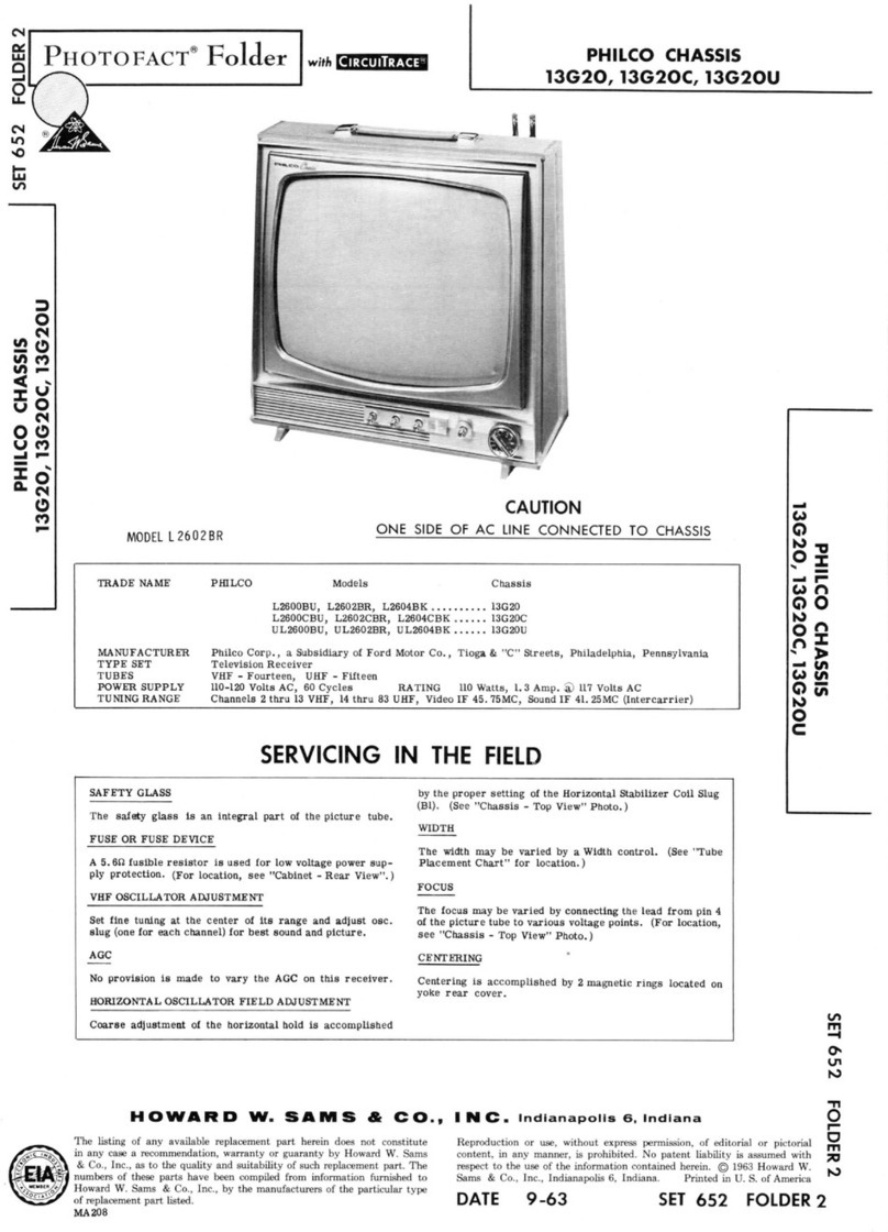
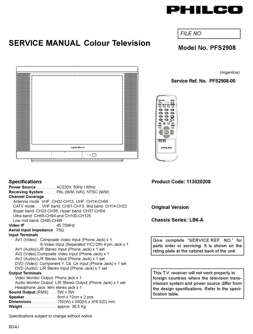
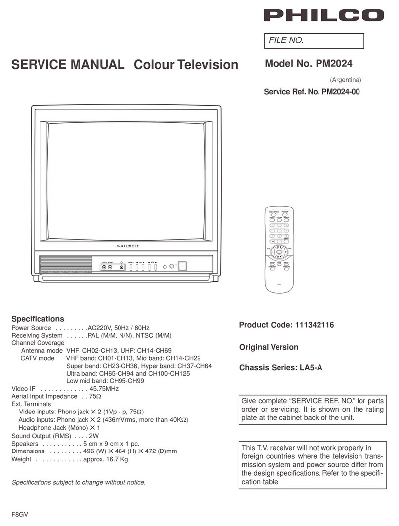
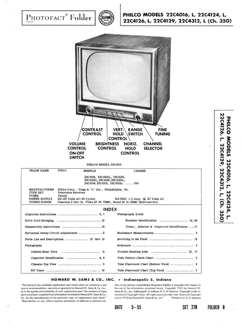
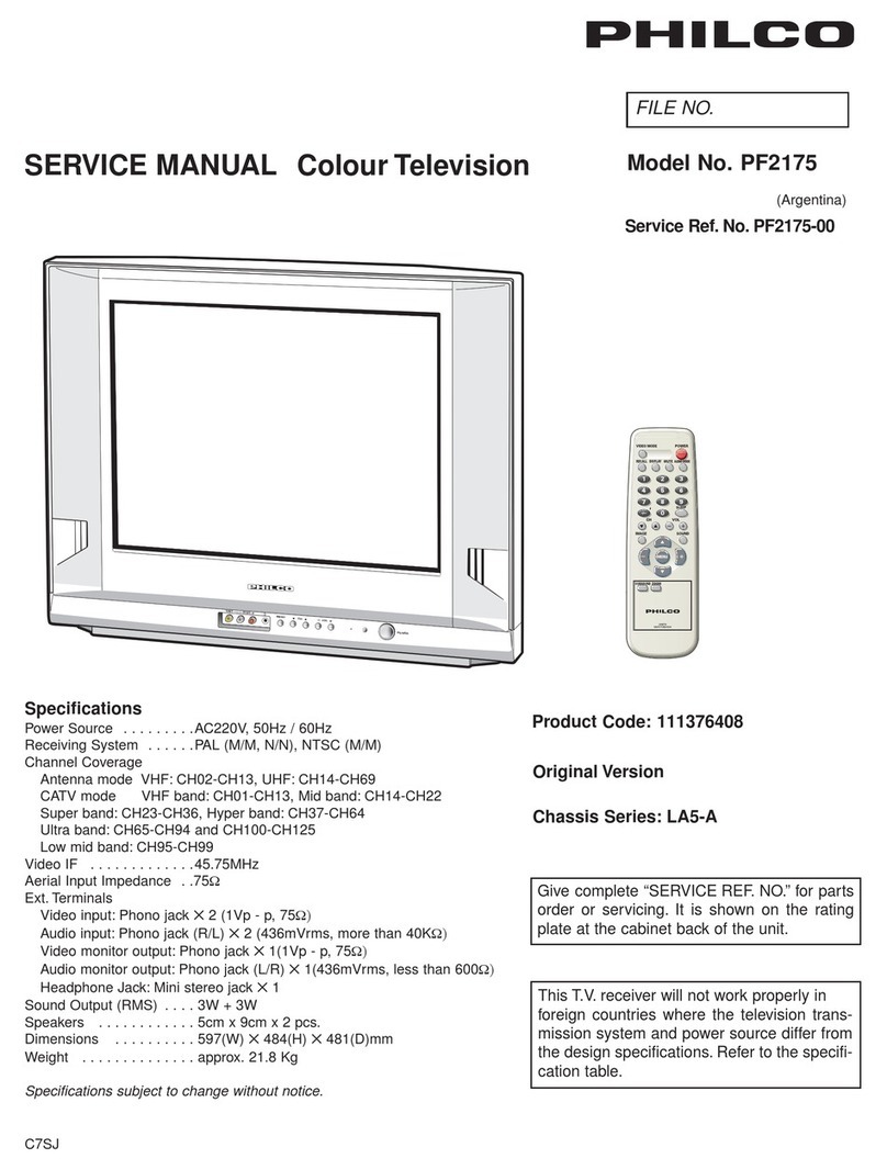
Philco PF2908 User manual

-1-
COLOR TELEVISION
CONTENTS
SERVICE MANUAL
29” NF TF SF CHASSIS
WITH NICAM
ⅠSAFETY PRECAUTION ………………………………………………… 1
ⅡSPECIFICATION ………………………………………………………… 2
Ⅲ IC’S GENERAL DESCRIPTION ……………………………………… 3
ⅣSPECIAL IC INTRODUCTION ………………………………………… 3
ⅤCHASSIS BLOCK DIAGRAM ………………………………………… 12
ⅥSERVICE MODE&ADJUSTMENT …………………………………… 13
ⅦTEST POINT WAVE FORM&SCHEMATIC DIAGRAM …………… 18

-1-
ⅠSAFETY PRECAUTION
1. X-RAY RADIATION PRECAUTION
1.1 Excessive high voltage can produce potentially hazardous X-RAY RADIATION. To avoid such hazards
the high voltage must be specified limit. The normal value of the high voltage of this receiver is 29” 29KV
±500V under 230V AC power source. The high voltage must not exceed 30KV for 29” TV
1.2 Each time a receiver requires servicing the high voltage should be checked following the HIGH
VOLTAGE CHECK procedure in this manual. It is recommended the reading of the high voltage be
recorded as a part of the service record. It is important to use an accurate and reliable high voltage meter.
1.3 The primary source of X -RAY RADIATION in this TV receiver is the picture tube. For continued X-RAY
RADIATION protection, the replacement tube must be exactly the same type tube as used in this TV
receiver.
1.4 Some parts in this receiver have special safety-related characteristics for X-RAY RADIATION protection.
For continued safety, parts replacement should be undertaken only after referring the PRODUCT SAFETY
NOTICE below.
2. GENERAL SAFETY PRECAUTION
The following are the necessary precautions to be observed before servicing this chassis
WARNING: Service should not be attempted by anyone unfamiliar with the necessary
2.1 Since the power supply circuit of this receiver is directly connected to the AC power line. An isolation
transformer should be used during any dynamic service to avoid possible shock hazard.
2.2 Always discharge the picture tube anode to the CRT conductive coating before handling the picture
tube. The picture tube is highly evacuated and if broken, glass fragments will be violently expelled. Use
shatterproof goggles and keep picture tube away from the unprotected body while handling.
2.3 When replacing a chassis in the cabinet, always be certain that all the protective devices are put back
in place, such as: nonmetallic control; knobs, insulating covers, shields, isolation resistor-capacitor,
network, etc.
2.4 Connection wires must be kept away from components with high voltage or high temperature.
2.5 When replacing parts or circuit boards, disconnect the power cord.
2.6 When replacing a high voltage resistor (metal oxide resistor) on circuit board, keep the resistor APP.
10mm (1/2 in.) away from circuit board.
2.7 If any fuse in this TV receiver is broken, replace it with the FUSE specified in the chassis parts list.
2.8 The receiver is designed to operate with 230V (50Hz) AC mains.
3. PRODUCT SAFETY NOTICE
Many electrical and mechanical parts in this chassis have special safety-related characteristics are often
passed unnoticed by a visual inspection and the X-RAY RADIATON protection afforded by them cannot
necessarily be obtained by using replacement components rated for higher voltage. The use of substitute
replacement parts that do not have the same safety characteristics as specified in the parts list may create
shock, fire, X-RAY RADIATION or other hazards.
Warning!
There are no any repairable components in this TV set. Do not try to make any change to it. High voltage
inside may cause danger.
ⅡSPECIFICATION
-2-
RF SYSTEM COLOR SYSTEM: PAL NTSC
SOUND SYSTEM:N M
VIDEO SYSTEM PAL NTSC4.43 NTSC3.58
TUNING SYSTEM FREQUENCY SYNTHESIS TUNING
PROGRAM PRESET 181
AV JACKS 1 Front AV jack IN;1 Rear AV jack IN;1 S video jack;1YUV jack
1 Audio out & 1 Video out
ANTENNA INPUT 75(UNBALANCE)
AUDIO OUTPUT ≥5W
MAIN POWER 170-240V AC 50/60Hz
POWER CONSUMPTION 29” 120W
ⅣCHIP INTRODUCTION
2. OM8373
The OM8373 combine the functions of a video processor together with a u-controller and US Closed Caption decoder .
The OM8373 contains a PAL/NTSC decoder, the OM8373 an NTSC decoder ,
The ICs are intended to be used in economy television receivers with 110 picture tubes.
The ICs have supply voltages of 8V and 3.3V and they are mounted in a SDIP-64 envelope.
The features are given in the following feature list.
2.1 Main features

-3-
2.2 Pin description

-4-

-5-
2.3 Block diagram

-6-
3. TDA4863AJ
The TDA8174A are deflection boosters for use in vertical deflection systems for frame frepuencies up to
200Hz.for the TDA4863AJ the flyback supply voltage will be generated internally by doubling the supply
voltage and therefore a separate flyback supply voltage is not needed.
3.1 Main features
Power amplifier with differential inputs
Output current up to 3A (p-p)

-7-
High vertical deflection frequency up to 200Hz
High linear sawtooth signal amplification
Flyback generator
Internally doubled supply voltage (two supply voltages only for DC-coupled outputs)
3.2 Pin description
3.3 Block diagram
4. LA42352
The LA42352 is 5W 2-channel AF power amplifier with DC volume control intended for televisions.
4.1 Main feature

-8-
Po 5W×2ch (RL = 8@THD = 10% VCC = 18V)
Built-in DC volume Control
Built-in Standby function
Built-in overheat protection
4.2 Pin description
4.3 Block diagram
5. TDA9850
5.2 Pin description

-9-
5.3 Block diagram

-10-
ⅥSERVICE ADJUSTMENT
POWER SUPPLY
1. Receive normal colour bar signal.
2. Connect DC voltmeter to D628- and isolated ground.
3. Adjust potentiometer in power unit to get the voltage as 110V ±1.0V for 21 inch hereinafter,
125V ±0.5V for 29 inch upwards.
FOCUS ADJUSTMENT
1. Receive a crosshatch signal.
2. While watching the screen, adjust the FOCUS VR to make the vertical and horizontal lines as fine and sharp as
possible.
SERVICE ADJUSTMENT
To enter service mode, Press “FACTORY” key on the Remote control unit of factory, or input “6483” code in picture menu.
On TV screen “FACTORY” will be indicated, this means entered aging mode.
Press “FACTORY” key or input “6483”, to exit “FACTOYR” mode and enter “B/W BANLANCE” mode. In “B/W BANLANCE”
mode, Adjust correspond item to get the best status of Black and white balance.

-11-
Press “FACTORY” or “MENU” key, to exit “B/W BALANCE” mode and enter “ADJUST” mode. In “ADJUST” mode, Press
“0” to “7“ key and corresponding on-screen display will be appeared.
And press following key, each function will be available.
Remote Hand Unit keys
MENU0 Geometrical and E/W adjustment
Receive PAL standard Complete pattern signal.
Adjustment steps:
a) Adjust V SL, to the center horizontal line just appeare from half bottom shadow.
b) Adjust V SI, to get 90% of vertical picture contents would be displayed on CRT.
c) Adjust V SH, the center horizontal line correspond to CRT vertical center.
d) Adjust H PH, to get the picture horizontal center correspond to CRT horizontal center.
e) Adjust EW WIDTH, to get 90% of horizontal picture contents would be displayed on CRT.*
f) Adjust EW PARA, to adjust EW parabola width.*
g) Adjust UP CORNER and LO CORNER, to correct EW upper/lower corner parabola.*
h) Adjust H-PARA and H-BOW, to correct EW Horizontal/Bow parallelogram.*
i) Adjust EW TRAPE, to correct EW trapezium.*
* E/W is only available for OM8373-serials.
MENU1 AGC Adjustment.
Receive 60dB(1mV)VHcolour bar pattern signal,adjust AGC value(voltage from high to low),to noise reduce gradually
and just disappeared point.
Black / White BANLANCE adjustment
CRTcut off and white balance adjustment.
Switch to TV signal.
a) CRT cut off adjustment.
1. Press “MUTE” key, then automatically vertical scan will be stopped.
2. Adjust SCREEN control on Flyback transformer to get the darkest single horizontal line (red, green, or blue,
sometimes shows more yellow, more purple or more white).
Receive white signal.
b) White balance adjustment.
1. Adjust DRI R/DRI G to get colour temperature as x=281, y=311
c) Sub-Brightness adjustment. (Use stair case signal)
1. Select menu7 in “ADJUST” mode.
2. Adjust SUB BRI to get the darkest step being cutoff.
Horizontal line
Shadow
a
V+/V-: volume adjustment
TV/AV: tv/av switching
0~7,MUTE: menu 0~7
P.P: PP mode setting
FACTORY,MENU: exit service mode

-12-
I2C standard UOC for export bus control adjustment item default setting
PAGE Items Variable Preset recommendation
B/W DRI R 63 White point R Adjustment 32
DRI G 63 White point G Adjustment 32
DRI B 63 White point B Adjustment 32
CUT R 63 Black level offset R Adjustment 32
CUT G 63 Black level offset G Adjustment 32
BT 63 Brightness of service mode 32
CT 63 Contrast of service mode 32
P.P Mild / Standard /
Dynamic
P.P mode indicator
BRIGHT 100 Brightness in pp mode
CONTRAST 100 Contrast in pp mode
COLOR 100 Color in pp mode
SHARP 100 Sharpness in pp mode
M0 FREQUENCY Field frequency indicator
H PH 63 Horizontal position adjustment 32
V SL 63 Picture vertical center adjustment 32
V SH 63 Vertical positions adjustment 32
V SI 63 Vertical amplitude adjustment 32
V SC 63 Vertical S Correction Adjustment 32
* EW WIDTH 63 EW width adjustment 32
* EW PARA 63 EW parabola width adjustment 32
* UP CORNER 63 EW upper corner parabola correction
adjustment
32
* LO CORNER 63 EW lower corner parabola correction
adjustment
32
* H-PARA 63 Horizontal parallelogram correction adjustment 32
* H-BOW 63 Horizontal bow correct adjustment 32
* EW TRAPE 63 EW trapezium correction adjustment 32
* Only available for OM8373-serials
M1 AGC 63 Tuner AGC Takeover Point Adjustment 24
AGC-SPEED 3 AGC speed 1
CORING 3 Coring adjustment 0
* OSVE ON/OFF Black current measuring lines in overscan
selection
ON
* HCO ON/OFF EHT tracking mode selection ON
WIDE 63 Wide mode adjustment 17
ZOOM 63 Zoom mode adjustment 50
* Only available for OM8373-serials

-13-
M2 UOC VOL SW On/Off Volume control mode selection
Off: By external hardware ( PWM or TDA9859)
On: By internal UOC
OFF
UOC / PWM VOL 63 The volume control of internal UOC(when UOC
VOL SW=on) or PWM(when UOC VOL SW=off)
63
VOL10 63 The 1th point of S-curve 10
VOL25 63 The 2th point of S-curve 25
VOL50 63 The 3th point of S-curve 50
VOL100 63 The 4th point of S-curve 100
FMWS 2 Widow selection of narrow-band sound PLL 0
AVL OPT On/Off Auto volume leveling selection On
AGN On/Off Gain FM demodulator
Off: normal operation On: gain +6dB, to be used
for the demodulation of mono signals in the NTSC
system
Off
M3 AV OPT On/Off AV Control logic selection
AV OPT OFF ON
PIN 62 63 62 63
TV L L H H
AV2 L H L H
SVHS H H L L
OTHER H L L L
OFF
AV CFG 0~8 The composition of AV source:
0: TVAV1
1: TVAV1AV2
2: TVAV1AV2SVHS
3: TVAV1AV2SVHSYUV
4: TVAV1AV2YUV
5: TVAV1SVHS
6: TVAV1SVHSYUV
7: TVAV1YUV
3
VIDEO OUT IF/CVBS Selected video out (pin38) CVBS
Pin5
Multi-Function Pin definition:
Vol1: L-channel volume control output
Vol2: R-channel volume control output
NTSC: system control output (control the sound
trapping filter, switch M/N system)
DVD: DVD power control output
MUTE: MUTE mode 1 control output
5060: field frequency indicator output
MUTE1: MUTE mode1 control output
MUTE2: MUTE mode2 control output
SV-DT: S-video-detected pin input
NTSC
Pin7 See PIN5 VOL1
Pin8 See PIN5 VOL2

-14-
BAND ON/OFF FS-Tuning band control selection OFF
FREQ LH 100.25M~
227.75MHz
The frequency of dividing-point between VHFL and
VHFH
164.25MHz
FREQ HU 300.50M~
555.50MHz
The frequency of dividing-point between VHFH and
UHF
428.50MHz
DVD IN OFF/ YC/
YUV
The source of DVD signal selection 0FF
DVD DELAY 0~8S Delay time of black-scren during switching to DVD 2
MULTI SYSTEM ON/OFF Multi-system selection ON
M4 VP 7~63 Vertical position of OSD adjustment 38
HP 63 Horizonital position of OSD adjustment 9
MENU TITLE 63 The color of menu title selection 61
YUV HS 63 YUV Horizontal position adjustment 52
YUV OSD HS 60 YUV Horizonital position of OSD adjustment 38
OSD L 0~3 The contrast of OSD adjustment 0
HALFTONE ON/OFF Contrast reduction of menu background
adjustment
ON
M5 IF 38/38.9/
45.75/58.75
Vision IF of RF 45.75
BTSC MODE BTSC mode selection
BTSC-ST 15 Noise threshold for stereo adjustment 7
BTSC-SP 15 Noise threshold for SAP adjustment 7
BTSC-LI 15 Input level adjustment 12
BTSC-A1 31 Stereo alignment data for wideband expander 22
BTSC-A2 31 Stereo alignment data for spectral expander 12
BTSC-TC 7 Timing current alignment data 4
BTSC-STS ON/OFF Stereo level switch selection OFF
BTSC-ADJ Auto adjustment function
M6 POW 0~2 AC power on start selection
0:Standby 1:Power on 2:Memory
1
LOGO ON/OFF LOGO selection OFF
SAVER ON/OFF Screen saver selection OFF
GAME ON/OFF Game selection ON
POWER ON TIME 6~15S Delay time of black-scren during power on 8
TIME FORMAT ON/OFF Time format selection (12H or 24H) ON
AKB ON/OFF Black current stabilization selection ON
NBL ON/OFF No black current loop application selection ON
SC.BRI 63 Brightness of screen line 8
FADE IN ON/OFF Fadein effect selection ON
STANDBY TM ON/OFF The ways of power-off selection OFF
PWL 15 Peak white limiting adjustment 15
M7 SUB CON 63 Sub contrast adjustment 32

-15-
SUB BRI 63 Sub brightness adjustment 32
SUB COL 63 Sub color adjustment 32
SUB SHA 63 Sub sharpness adjustment 32
SUB TIN 31 Sub tint adjustment 16
YDL PAL 15 Y-delay adjustment for PAL signal 2
YDL NTSC 15 Y-delay adjustment for NTSC signal 2
YDLY AV 15 Y-delay adjustment for AV mode 2
CATHE 15 Athode voltage adjustment 8
3.KEYPAD DEFINITION
4.LOGO EDIT
To enter logo edit mode, Press “LOGO” key on the Remote control unit of factory.On TV screen two logo line will be
displayed, you can press following key to edit logo display.
Press ”1” key to select line 1 or line 2.
Press “2” key to change color of current logo line.
Press “3” key to change size of current logo line.
Press “4”,”5” key to move current logo line left or right.
Press “6”,”7” key to move current logo line up or down.
Press “0” key to delete character at the cursor position.
Press “V+/-” key to move the cursor one character position backward or forward.
Press“P+/-” key to select character at the cursor position, the character you could selected as following:
“ABCDEFGHIJKLMNOPQRSTUVWXYZabcdefghijklmnopqrstuvwxyz0123456789?.!*#/+-”
Press “LOGO” key to exit logo edit mode.
Function POWER MENU TV/AV V- V+ P- P+
Voltage
range
11/16~12/16
VDD
9/16~11/16
VDD
7/16~9/16
VDD
5/16~7/16
VDD
3/16~5/16
VDD
1/16~3/16
VDD
0/16~1/16
VDD
VDD=3.3V

A
B
C
D
D
C
B
A
R518
1.5K
R528
1.5K
R538
1.5K
C543
1000pF/2KV
H-Gnd
C152
100uF/16V
1
3
5
4
2
SF201 M1859M30
C201
10nF
R139
100
WP
1
n.c.
2
A2
3
Vss
4
Vdd 8
PTC 7
SCL 6
SDA 5
IC102
ST24C08
R149
100
R150
100
C110
1uF/50V
R111
15K
C105
47uF/10V
L101
10uH
C112
2.2uF/50V
C116
100nF
R112
39K
R130
100
R140
100
R203
27K
R202
15K
R206
680
R136
100
R135
100
R134
100
R133
10K
X101
12MHz C142
33pF
C143
33pF
R101
3.3K
R103
3.3K
R102
3.3K
+
C203
22uF/50V
L104
10uH
C138
47uF/16V
C141
47uF/16V
L106
10uH
L103
10uH
SF102
XT-4.5
R119
390
C125
100nF
C127
100uF/16V
L105
10uH
C119
10uF/16V
R116
2.2K
C131 1nF
C130
50V/1U
Q101
2SC1815
R115
2.7K
R117
27K
C124
102pF
L102
10uH
R120
1K
R126
47
C128
47uF/16V
R129
330
R122
220
R155
2.2K
Q102
2SC1815
SW107
TV/AV
R145
470E
R144
1K
R143
2.2K
R141
5.6K
R429
100
R427
100
C135
22nF
C134
22nF
C133
22nF
R104
47
C122
50V4.7UF
R108
3.3K
C103
1nF
D101
C144
10nF
+C145
47uF/16V
ZD201
5.1V
2
R201
2W/39E
Q531
2SC2482
Q532
BF422
R511
47
R521
47
R531
47
R532
10K
ZD104
8.2V
R413 100
ZD105
8.2V
R412
100
ZD106
8.2V
R411 100
R409
470E
CRT
TU201
TDQ-BFSNS2/2
CrCb
Y
R1-in
L1-in
V1-in
Rout Lout Vout
+8V
IF
MB
SDA
SCL
33V
SW106
P+
SW105
P-
SW104
V+
SW103
V-
SW101
MENU
C205
47uF/16V
+8V
C120
820pF C121
472pF
C117
222pF
C113 102PF
C111 100nF
C109
472pF
C108 222pF
C107
220nF
C106
10nF
+8V
C104 220nF
+33V
R125
3.3K
C151
10nF
R137
3.3K
R138
3.3K
C140
10nF
+5V
C139
10nF
ZD101 7.5V
ZD102 7.5V
ZD103 7.5V
B
G
R
R533
300
C531
330pF
R534
47
Q533
BF423
R536
330
ZD501
HZ9A3
1
2
3
4
HV
FOCUS
SCREEN
GND
1
A2
+8V
C
Y
200V
C126
10nF
+8V
HEATER
GND
C123
?
T3P03 SCHEMATIC DIAGRAM
0Y 1
2Y 2
YCOM 3
3Y 4
1Y 5
EN 6
VEE 7
GND 8
S1
9
S0
10
3X
11
0X
12
XCOM
13
1X
14
2X
15
VDD
16
IC401
CD4052
AS
AGC
C202
10u/50V
R128
390
C129
50V/1U
R410
75E
C411 47pF
C412 47pF
C413
47pF
R406
47K
R405
47K
C409
47pF
C407 1000P
C408
1000P
C103
16V/47U
C429
47pF
C427
47pF
+C101
47u/16V
C102
10nF
C101
0.1uF
R408
100
C415
47u/16V
+8V
R121
180
R202
100
R201
100
POWER
SCL
SDA
VOL1
VOL2
C426
50V/1U
C430
50V/1U
R131
33K
R132
22K
C137
560pF
C418
50V/1U
R147
3.9K
R105
3.9K
SCL
SDA
SDA
SCL
E/W
VDRA
VDRB
FSC
ABL
B-IN
G-IN
R-IN
CVBS-IN
CVBS-OUT
AV2
AV1
AV2
AV1
CVBS-OUT
L-OUT
R-OUT
L1-IN
R1-IN
C508
1nF
C136
50V/4.7U
R139
10
+5V
C207
1nF C208
1nF
TP22
+8V
IF1
IF2
IF1
IF2 AGC
AGC
KEY
KEY
IR
IR
+5V
C
Y
V1-in
V1-IN
CY
V2-in
Vi2
Li2
Ri2
R420
82E
R421
47K
R424
47K
R2-IN
L2-IN
AV2-IN
V2-in
1
R321
1E
1
R325
330E
R320
5.1E
C320
25V/220uF
1
2
3
4
5
XS301
CON5
1
R324
1.5
L301
23uH
EHT
D305
RGP15J
D304
RGP15J
R306
1E/2W
V
D308
RGP15J
C304
220pF/500V
Focus
H
G2
C305
10uF/250V
R305
220K
C321
1uF/250V
2
R399
3.9E/3W
R307
1K
C306
47nF
D311
1N4148
ZD301
HZ15-3
R309
680
R310
1K
T301
JDT1924
2
R317
2W/56E
C301
50V/2200P
R301
2.2K
R303
100
C313
1600V/6800P
C314
1600V/8200P
C311
400V/0.33uF
R308
4.7K
ZD302
HZ9A2
R313
4.7K
R318
220E
D307
RGP10G
13V
-13V
R311
470K
1
R332
10K 1W
R314
10K
FBLY
EHT/Protect
ABL
Hout
D310
1N4148
R316
5.6K
T302
BSC25-N0301
8
2
1
10
3
5
6
7
4
9
L302
700uH
C324
100V/6.8uF
2
R328
5.1/2W
R330
4.7K
C322
47nF
Q303
IRFS630A
R329
100K
C323
470pF
R331
220
EW
C315
400V/0.027uF
D301
GBY228
D302
RGP15J
C316
2KV/470P
1
R312
1K
D306
RGP15J
C307
35V/470uF
D303
1N4004
R326
2.2K
C319
47nF/50V
D314
BYD33D
C309
100uF/50V
R322
2.2K
C318
6800P
C317
1000P
C310
0.1uF
VDRA
VDRB
FM
SCL
SDA
+9V
R902
150
R901
8.2K
C902
50u/16V
C904
50V/4.7uF
C903 104
C901
473
C905
101
C906
101
R904
100
R905
100
C926
50V/4.7uF
FM
C907
100u/16V
C911
474
C909
224
C908
50V/4.7uF
R903
2.2K
C910
50V/10uF
C920
50V/1uF
C919 50V/1uF
C918 50V/10uF
C917
50V/10uF
C925 50V/2.2uF
C922
16V/100uF
C914 50V/2.2uF
C921
1u/50V
C913 50V/4.7uF
C912 50V/4.7uF
C924 1u/50V
C916 104
C915
153
X901
Y
Cb
Cr
R118
100K
EHT/Protect
R O
L O
XP101 GND
B-out
G-out
R-out
Blank
CER 17
CMO 18
CSS 19
CR 20
OUT R 21
CSDE 22
SAP 23
VREF 24
CL 25
CND 26
OUT L 27
MAD 28
CTW 29
CTS 30
CW 31
CS 32
CADJ
16
CPH
15
CP2
14
CP1
13 VCAP
12
COMP
11
VCC
10
SCL
9
SDA
8
DGND
7
AGND
6
CDEC
5
CM
4
CN R
3VEI
2
VEO
1
IC901
TDA9850
H out
FBLY
D313
1N4148
R327
1.8K
0Y 1
2Y 2
YCOM 3
3Y 4
1Y 5
EN 6
VEE 7
GND 8
S1
9
S0
10
3X
11
0X
12
XCOM
13
1X
14
2X
15
VDD
16
IC402
CD4052
C420
47u/16V
+8V
AV1
AV2
RO
LO
C432
50V/1uF
C431
50V/1uF
R1-IN
L1-IN
C403
0.01uF
C416
50V/1uF
R2-IN
L2-IN
C402
0.01uF
C415
50V/1uF
R-OUT
L-OUT
R416
15K
R415
22K
R414
10E
+3.3V
R113
5.6K
R
D531
1N4148
D532
BAV21
R537
220E
Q521
2SC2482
Q522
BF422
R522
10K
R523
300
C521
330pF
R524
47
Q523
BF423
R526
330
D521
1N4148
D522
BAV21
R527
220E
Q511
2SC2482
Q512
BF422
R512
10K
R513
330
C511
330pF
R514
47
Q513
BF423
R516
330
D511
1N4148
D512
BAV21
R517
220E
R535
2W/12K
R525
2W/12K
2
R515
12K
XS502
GND
B-out
G-out
R-out
Blank
Standby
1
SCL
2
SDA
3
LED
4
MUTE
5
Key
6
VOL1
7
VOL2
8
Vss C/P
9
SYS1
10
SYS2
11
VssA
12
SECPLL
13
Vp2
14
DECDIG
15
PH2LF
16
PH1LF
17
Gnd3
18
DECBG
19
AVL/EWD
20
VDRB
21
VDRA
22
IF1
23
IF2
24
IREF
25
VSC
26
Tuner AGC
27
AUDEEM/SIF1
28
DECSDEM/SIF2
29
Gnd2
30
SNDPLL/SIFAGC
31
AVL/REFO
32 H. out 33
FBISO 34
AUDEXT/QSSO 35
EHTO 36
PLLIF 37
IFVO/SVO 38
Vp1 39
CVBSINT 40
Gnd1 41
CVBS/Y 42
CHROMA 43
AUDOUT/AMOUT 44
INSSW2 45
R2/Vin 46
G2/Yin 47
B2/Uin 48
BCLin 49
Blanking 50
Rout 51
Gout 52
Bout 53
VddA 54
VpE 55
VddC 56
OscGnd 57
XTALin 58
XTALout 59
Reset 60
VddP 61
AV1 62
AV2 63
IRin 64
IC101
OM8373
VP1
1
VP3
2
VP2
3
GND
4
Vout
5
IN-
6
IN+
7
IC301
TDA4863AJ
CVBS-IN
+8V
Vout
GND
Vin
IC602
7808
C610
47uF 16V
+9V
C621
0.1uF
C619
0.1uF/s
3
2
5
11
12
13
16
17
15
8
T604
Q613
ST1802HI
2
R625
68/3W
C616
680pF 2KV
R629
12M/0.5W
C629
2200PF 400VAC
Q612
2SC3807
C617
22n/M
5
R624
27/5W
C615
15n/M
R615
22K
R622
15K
R621
180K/0.5W
R620
180K/0.5W
R619
47
C614
0.1uF/M
R617
1K
IC601
H11A817B/C
C613
4n7/M
D603
RM11C
C603
1n 1KV
C607
220uF 400V
D614
1N4148
D617
ES1
D616
1N4148
R611
5K6
Q611
2SA1015Y
5
R602
1E8/5W
RT601
MZ72 K9RM270
T601
ET-LB-2868
C601
0.22uF/250VAC
F601
T3.15A
SW601
KDC-A11
XS602
XS603
C627
500V/470P
D627
RU4YX
D628
RU4AM
C628
1KV/470P
C632
25V/470uF
C630
160V/47uF
Q631
2SC1815Y
R643
150K
R636
15K 1/6W
VR631
2K
ZD602
6V2
R618
22K
R612
15K 1/6
C685
0.22uF 50V
R653
1K
R626
2K2
+33V
+125V
2
R616
2W/12K
IC604
UPC574
C608
1uF 50V
Q683
B892
R654
15K
Vout
GND
Vin
IC603 7805 +5VA
ZD601
HZ11C
R623
2K7
1
2
4
3
D604
RM11C
D605
RM11C
D606
RM11C
C605
1n 1KV
C620
0.1uF
+15V
D626
RU4YX
C626
470pF/500V
C625
25V/470uF
+20V
C612
47uF 16V
C609
16V/470uF
R614
3.3K
D615
1H4148
Q608
2SC1815Y
Q401
2SC1815Y
C419
16V/10uF
R404
1K
Q402
2SC1815Y
C417
16V/10uF
R401
1K
+8V
R402
220K
R403
220K
D611
1N4148
RL601
JZC-36F-012
Q614
2SA1815Y
R610
10K +8V
XS701
TJC3-4A
L
R
I R
IC103
HS0038B8
R128
1K
R127
510
Q401
2SA1815Y
C414
16V/47uF
+8V +5V
POWER
+8V
C303
50V/4700P
D309
FR104
R302
22K
R304
27K
+15V
Q301
C2383
Q302
2SC5296
C717
16V/100uF
C718
16V/47uF
C719
16V/47uF
Ripple Filter
IN1
PRE GND
N.C.
IN2
PWR GND
STB
OUT1
P.P
N.C.
VCC
OUT2
N.C.
1234567 98 1110 12 13
IC701 LA42352
C701
16V/1uF
C702
16V/1uF
C703
50V/2200P
C704
50V/2200P
R702
10K
R701
10K
R703
1K
R704
1K
C707
25V/470uF
C708
25V/470uF
R705
1/4W 4E7
R706
1/4W 4E7 C705
50V/0.1uF
C706
50V/0.1uF
R709
270K
C709
16V/10uF
C710
16V/10uF
C710
16V/10uF
R153
10K
R154
1.2K
R148
1.2K
Q403
2SC1815Y Q404
2SC1815Y
Q405
2SA1015
R408
10K
R407
10K
D401
1N4148
R417
10K
+8V
+20V
C404
16V/100uF
C712
25V/470uF
C720
50V/0.01uF
Q607
2SC1815Y R613
1K R110
1K
+5V
R123
820E
R107
820E
2
R906
2W/100E
ZD901
9.1V
R105
3.3K
2
R311
2W 1E
C316
160V/47uF
+140V
R335
10K +8V
C308
25V/220uF
C422
1000P
C421
1000P
C410
16V/10uF
C409
16V/10uF
R418
10E
C424
16V/10uF
2
R647
2W 27E
ZD604
3.3V
C634
16V/100uF
VOL1
VOL2
R711
2W 1E
XS401
CYB-3.2-8DW6-3-100
XS402
AV3
XS403
AV3
AV1-IN
OUT YUV
XP303
XS503
200V
HEATER
GND
+8V
+
C148
50V/10uF
C147
50V/1500P
C146
50V/1500P
R152
1.8K
R151 1.8K
Q406
2SC1815
Q407
2SC1815
+
C401
50V/10uF
+
C418
50V/10uF
R434
5.6K
R430
5.6K
R431
120K
R426
120K
R425
150E
R432
150E
R428
680E
R433680E
+8V
R207
100E
MUTE
Q104
2SC1815Y
R106
12K
R435
1K +8V
MUTE
2
R630
2W/15K
2
R627
2W/1K

1
1.9.T3P03001110 1
2
L301(2) 1.E.71287616300 2
3
L302(2) 1.E.71287616300 2
4
T604(4) 1.E.71287616300 4
5
Q302(3), 1.E.71287625300 3
Q613(2), 1.E.71287625300 2
T302(4), 1.E.71287625300 4
6
C607(2) 1.E.71287625300 2
7
R320 1.R.11051000300 1
8
R126, 1.R.11470000300 1
9
R521, 1.R.11470000300 1
10
R524, 1.R.11470000300 1
11
R531, 1.R.11470000300 1
12
R534 1.R.11470000300 1
13
R130, 1.R.11101000300 1
14
R139, 1.R.11101000300 1
15
R140, 1.R.11101000300 1
16
R204, 1.R.11101000300 1
17
R205 1.R.11101000300 1
18
R331, 1.R.11221000300 1
19
R517, 1.R.11221000300 1
20
R527, 1.R.11221000300 1
21
R537 1.R.11221000300 1
22
R129 1.R.11331000300 1
23
R127 1.R.11511000300 1
24
R206 1.R.11681000300 1
25
R110, 1.R.11102000300 1
26
R120, 1.R.11102000300 1
27
R307, 1.R.11102000300 1
28
R310, 1.R.11102000300 1
29
R613, 1.R.11102000300 1
30
R401, 1.R.11102000300 1
31
R404 1.R.11102000300 1
32
R148, 1.R.11122000300 1
33
R154 1.R.11122000300 1
34
R151 1.R.11182000300 1
35
R152 1.R.11182000300 1
36
R116 1.R.11222000300 1
37
R103, 1.R.11332000300 1
38
R108, 1.R.11332000300 1
39
R109, 1.R.11332000300 1
40
R125, 1.R.11332000300 1
41
R614 1.R.11332000300 1
42
R313 1.R.11472000300 1
43
R113, 1.R.11562000300 1

44
R611 1.R.11562000300 1
45
R153, 1.R.11103000300 1
46
R335, 1.R.11103000300 1
47
R610, 1.R.11103000300 1
48
R522, 1.R.11103000300 1
49
R532 1.R.11103000300 1
50
R106 1.R.11123000300 1
51
R622 1.R.11153000300 1
52
R618 1.R.11223000300 1
53
R304 1.R.11273000300 1
54
R131 1.R.11333000300 1
55
R118 1.R.11104000300 1
56
R319 1.R.11474000300 1
57
R324 1.R.12015000300 1
58
R705, 1.R.12047000300 1
59
R706 1.R.12047000300 1
60
R510 1.R.12220000300 1
61
R647 1.R.12330000300 1
62
R301 1.R.12221000300 1
63
R712, 1.R.12331000300 1
64
R713 1.R.12331000300 1
65
R308 1.R.12472000300 1
66
R643 1.R.12154000300 1
67
R619 1.R.14470000300 1
68
R325 1.R.14331000300 1
69
R518, 1.R.14152000300 1
70
R528, 1.R.14152000300 1
71
R538 1.R.14152000300 1
72
R305, 1.R.14184000300 1
73
R620, 1.R.14184000300 1
74
R621 1.R.14184000300 1
75
R322, 1.R.21222000100 1
76
R326 1.R.21222000100 1
77
R629 1.R.44126000301 1
78
C301 1.C.52507222500 1
79
C304 1.C.52887221500 1
80
C325, 1.C.52887471500 1
81
C326, 1.C.52887471500 1
82
C327 1.C.52887471500 1
83
C108 1.C.01502220400 1
84
C613, 1.C.01501530400 1
85
C615, 1.C.01501530400 1
86
C617 1.C.01501530400 1
87
C306, 1.C.01504730400 1
88
C319, 1.C.01504730400 1
89
C901 1.C.01504730400 1

90
C125, 1.C.01501040400 1
91
C614, 1.C.01501040400 1
92
C705, 1.C.01501040400 1
93
C706 1.C.01501040400 1
94
C116 1.C.21811040400 1
95
C103, 1.C.61164760600 1
96
C128, 1.C.61164760600 1
97
C138, 1.C.61164760600 1
98
C141, 1.C.61164760600 1
99
C145, 1.C.61164760600 1
100
C205, 1.C.61164760600 1
101
C414, 1.C.61164760600 1
102
C610, 1.C.61164760600 1
103
C612, 1.C.61164760600 1
104
C718, 1.C.61164760600 1
105
C719 1.C.61164760600 1
106
C105, 1.C.61161070600 1
107
C127, 1.C.61161070600 1
108
C404, 1.C.61161070600 1
109
C634, 1.C.61161070600 1
110
C717, 1.C.61161070600 1
111
C907, 1.C.61161070600 1
112
C922 1.C.61161070600 1
113
C609 1.C.61164770600 1
114
C611 1.C.61502240600 1
115
C110, 1.C.61501050600 1
116
C129, 1.C.61501050600 1
117
C130, 1.C.61501050600 1
118
C415, 1.C.61501050600 1
119
C416, 1.C.61501050600 1
120
C425, 1.C.61501050600 1
121
C426, 1.C.61501050600 1
122
C430, 1.C.61501050600 1
123
C431, 1.C.61501050600 1
124
C432, 1.C.61501050600 1
125
C618, 1.C.61501050600 1
126
C701, 1.C.61501050600 1
127
C702, 1.C.61501050600 1
128
C919, 1.C.61501050600 1
129
C920, 1.C.61501050600 1
130
C921, 1.C.61501050600 1
131
C924, 1.C.61501050600 1
132
C203 1.C.61501050600 1
133
C112, 1.C.61502250600 1
134
C914, 1.C.61502250600 1
135
C925 1.C.61502250600 1
This manual suits for next models
1
Table of contents
Other Philco TV manuals

Philco
Philco DTH-14V1FSN User manual

Philco
Philco HLS78D-I User manual

Philco
Philco PF2975 User manual

Philco
Philco PD2015 User manual

Philco
Philco PFS2908 User manual

Philco
Philco PH2190 User manual

Philco
Philco PF2175 User manual

Philco
Philco PS2114 User manual

Philco
Philco PH-1470 User manual

Philco
Philco 50-T1443 User manual