PHOTO
FACT*
Folder
PHILCO
MODELS
22C4O2O,
22C4128M,
22C4132L
(Ch.
TV4OO)
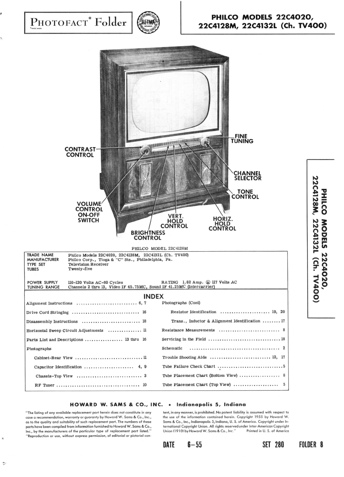
CONTRAST
CONTROL
VOLUME
CONTROL
ON-OFF
SWITCH
FINE
TUNING
CHANNEL
SELECTOR
TONE
CONTROL
VERT.
HOLD
CONTROL
BRIGHTNESS
CONTROL
PHILCO
MODEL
22C4128M
HORIZ.
HOLD
CONTROL
TRADE
NAME
Philco
Models
22C4020,
22C4128M,
22C4132L
(Ch.
TV400)
MANUFACTURER
Philco
Corp.,
Tloga
& "C"
Sts.,
Philadelphia,
Pa.
TYPE
SET
Television
Receiver
TUBES
Twenty-five
POWER
SUPPLY
110-120
Volts
AC-60
Cycles
RATING
1.82
Amp.
® 117
Volts
AC
TUNING
RANGE
Channels
2
thru
13,
Video
IF
45.75MC,
Sound
IF
41.25MC
(Intercarrler)
INDEX
Alignment
Instructions
6,7
DriveCord
Stringing
16
Disassembly
Instructions
18
HorizontalSweep
Circuit
Adjustments
II
Parts
List
and
Descriptions
13
thru
16
Photographs
Cabinet-Rear
View
11
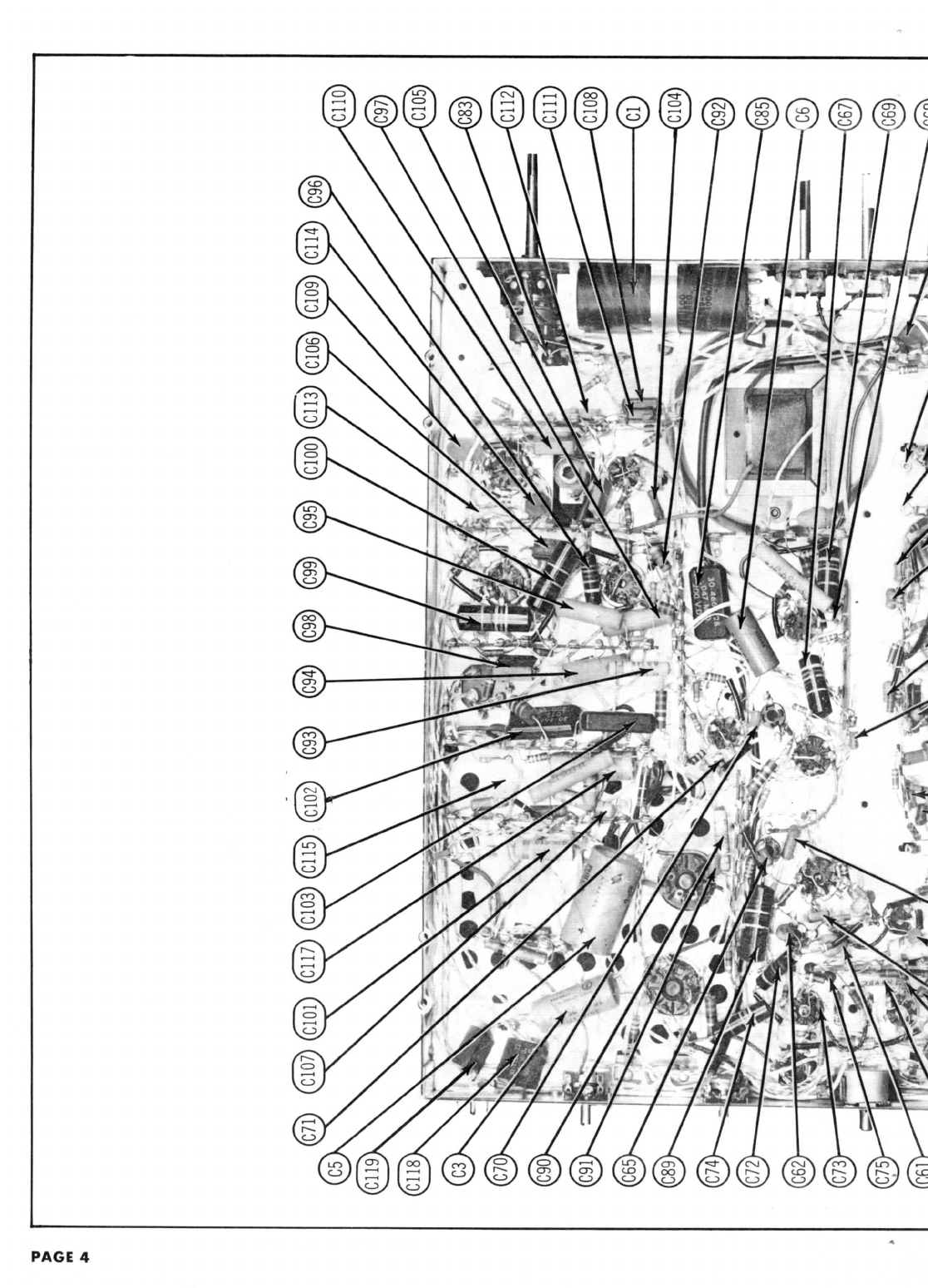
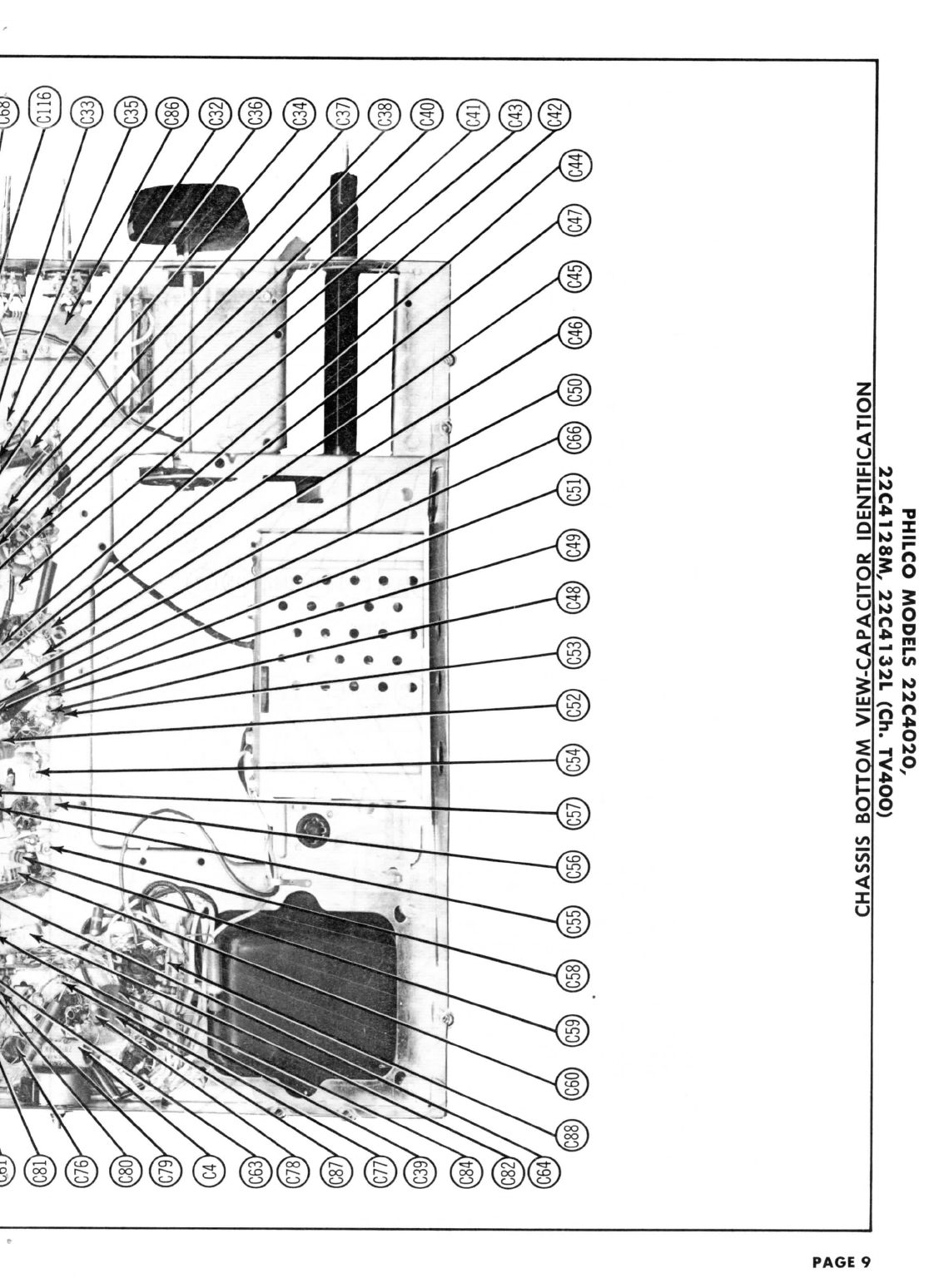
Capacitor
Identification
4,9
Chassis-Top
View
3
RF
Tuner
..
10
Photographs
(Cont)
Resistor
Identification
........
19,20
Trans.,
Inductor
&
Alignment
Identification
17
Resistance
Measurements
8
Servicing
inthe
Field
18
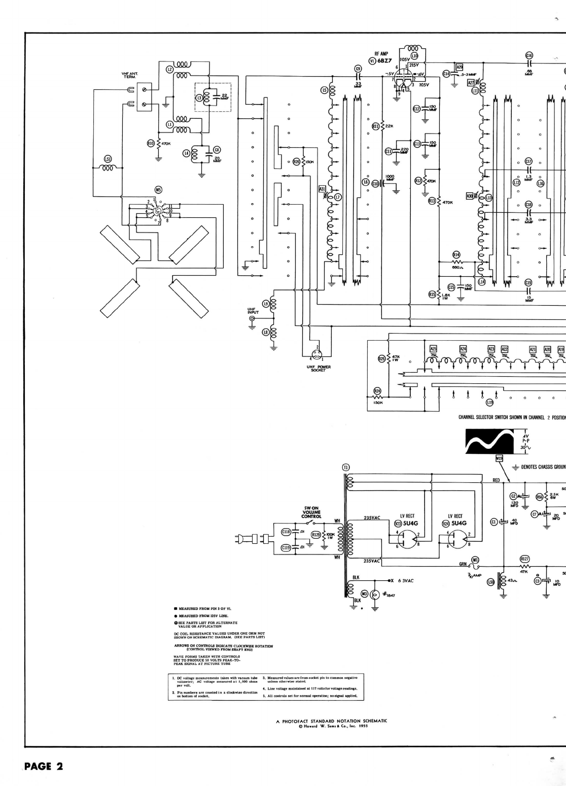
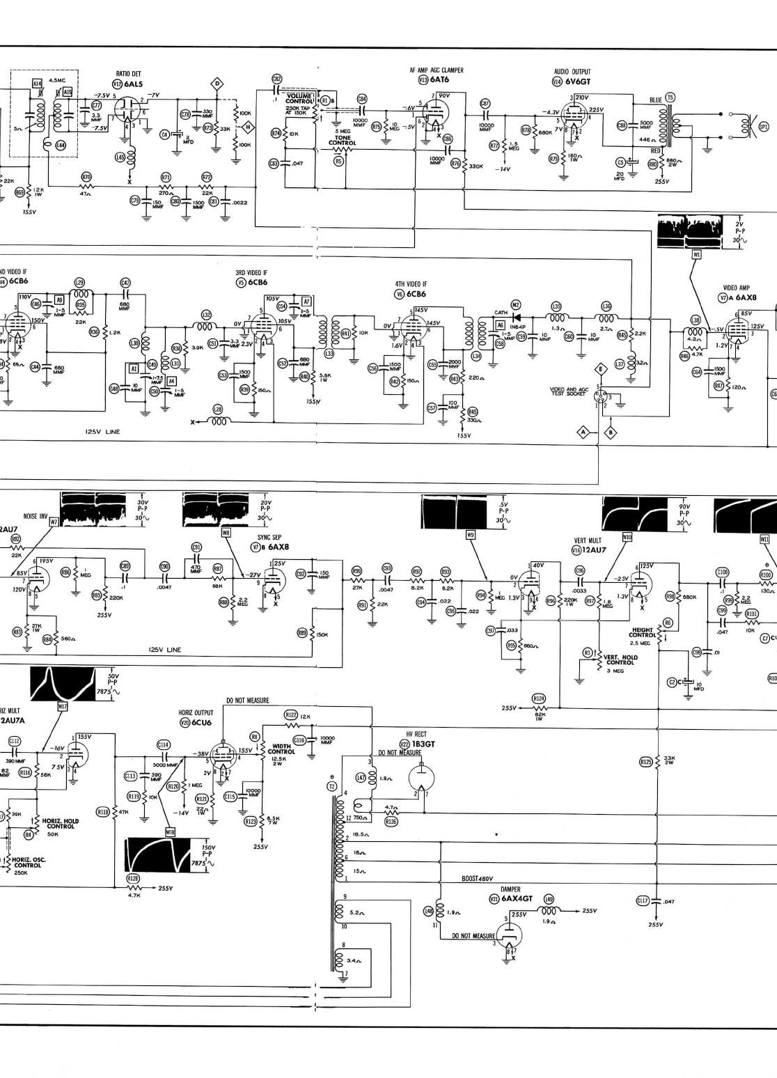
Schematic
2
TroubleShootingAids
12,17
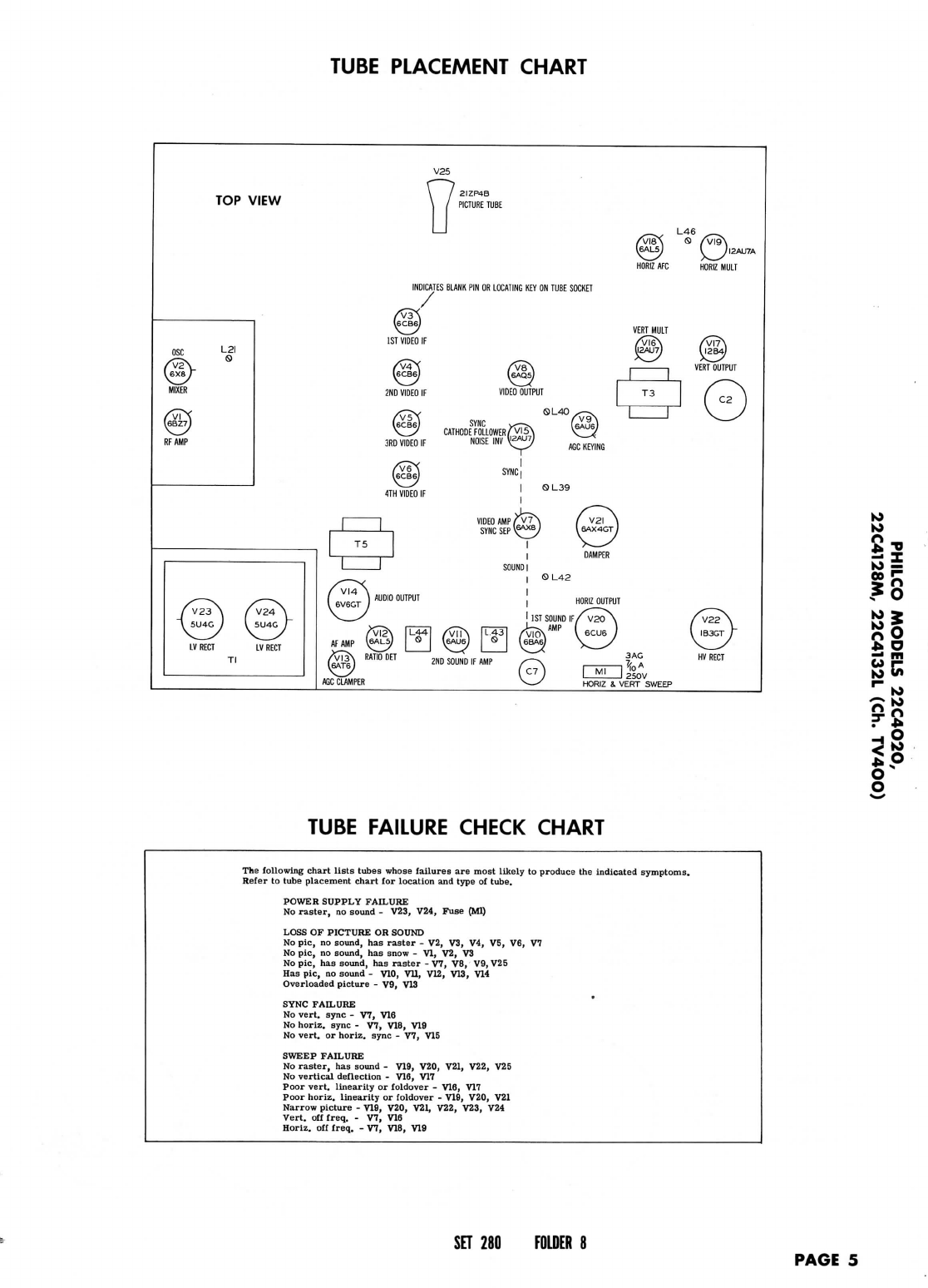
Tube
Failure
CheckChart
5
Tube
PlacementChart(Bottom
View)
..................
8
Tube
Placement
Chart(Top
View)
5
K>
K>
10
s
"o
o
*"*
to
PS
HOWARD
W.
SAMS
&
CO.,INC.
•
Indianapolis
5,
Indiana
"The
listing
ofany
availablereplacementpart
herein
does
not
constitute
inany
case
a
recommendation,
warranty
or
guaranty
by
Howard
W.
Sams
&
Co.,
Inc.,
as
tothe
quality
and
suitability
of
such
replacementpart.
The
numbers
of
these
parts
have
beencompiledfrominformation
furnished
to
Howard
W.
Sams
&
Co.,
Inc.,
bythe
manufacturers
ofthe
particulartype
of
replacement
part
listed."
"Reproduction
or
use,without
express
permission,
of
editorial
or
pictorialcon-
tent,
inany
manner,
is
prohibited.
No
patent
liability
is
assumed
with
respect
to
the
useofthe
informationcontainedherein.Copyright
1955
by
Howard
W.
Sams
&
Co.,
Inc.,
Indianapolis
5,
Indiana,
U.S.of
America.Copyright
under
In-
ternational
CopyrightUnion.
All
rights
reserved
under
Inter-American
Copyright
Union
(1910)
by
Howard
W.
Sams
&
Co.,
Inc."
Printed
inU.S.of
America
DATE
6-55
SET
280
FOLDER
8