GC9140
5-8
DETACHABLE MAT ASSY 56
TRAY ASSY 54
RUBBER FRONT LOCK 51
SLIDER CAM 52
SLIDER KNOB PLATED 53
COUPLING SEAL 50
STAND BODY 30
Remove DETACHABLE MAT ASSY 56
Remove Screws G1, G2, G3
Disassemble TRAY ASSY 54
Remove Screws H1, H2
Disassemble RUBBER FRONT LOCK 51
Remove Screws J1, J2
Disassemble SLIDER CAM 52
Disassemble SLIDER KNOB PLATED 53
Remove Screw K
Disassemble Rinse coupling plate
Disassemble COUPLING SEAL 50
Remove Screw L
Disassemble De-air coupling plate
Disassemble COUPLING SEAL 50
Remove (Torx T15) screws
M1, M2, M3, M4, M5, M6
Disassemble STAND BODY 30
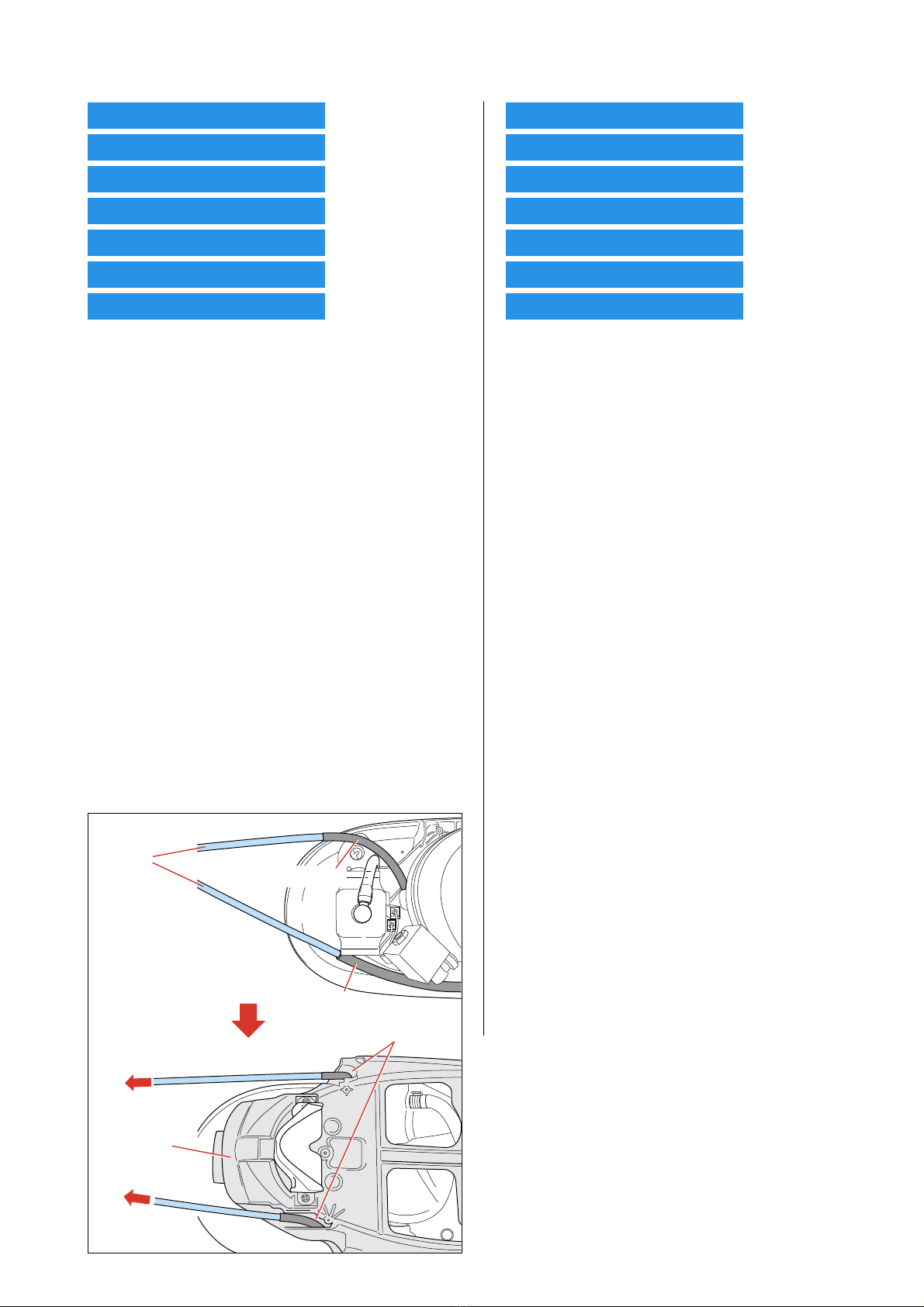
Re-assembly Note:
When re-assembling STAND BODY 30, make use of 2 guide
rods to insert the de-air tube & rinse tube through the designated
openings on the STAND BOBY 30.
Refer Picture below:
DISASSEMBLY ADVICE - STAND
DISPLAY PANEL ASSY 40
AUTO CORD WINDER 48
BOILER ASSY 36
MAIN PCB-PUMP ASSY 43
RINSE LED PCB 45
TANK SEAL PLATE ASSY 46
HALL SENSOR PCB 44
Remove (Torx T15) screws N1, N2
Disassemble DISPLAY PANEL ASSY 40
Remove Screws P1, P2
Disassemble AUTORINSE PCB 41
Remove Screws Q1, Q2
Disassemble STEAM SETTING PCB 42
Remove Screws R1, R2
Disassemble AUTO CORD WINDER 48
Remove (Torx T15) screws S1, S2
Disassemble Cord clamp
Disassemble HOSE CORD MOUNTED ASSY 13
Cut BOILER STRAP 37
Disassemble BOILER ASSY 36
Re-assembly Note:
When re-assembling BOILER ASSY 36, ensure BOILER PAD
38 are put in place as heat insulations between the BOILER
STRAP 37 & STAND BOTTOM ASSY 30.
Disengage All connectors on main PCB
Disengage All connectors & hose connections on
pump assy
Remove (Torx T15) screws T1, T2
Disassemble MAIN PCB-PUMP ASSY 43
Repair Note:
When either MAIN PCB or PUMP ASSY is defective, both
components MUST be replaced together as a pair, i.e. replace
with service kit MAIN PCB-PUMP ASSY 43.
Remove Screw U
Disassemble RINSE LED PCB 45
Remove Screws V1, V2
Disassemble TANK SEAL PLATE ASSY 46
Disassemble HALL SENSOR PCB 44
Guide
rods
Rinse tube
openings
De-air tube
STAND
BODY 30