Phoenix Contact Axioline P User manual

User manual
UM EN AXL P diagnostics
Axioline P diagnostic registers and error
messages

2020-03-03
PHOENIX CONTACT GmbH & Co. KG • Flachsmarktstraße 8 • 32825 Blomberg • Germany
phoenixcontact.com
4028_en_A
Axioline P diagnostic registers and error messages
Designation Order No.
AXL P BK PN AF 2316390
AXL P FBPS BASE 2316393
AXL P FBPS 28DC/0.5A 2316394
User manual
This user manual is valid for Axioline P products
UM EN AXL P diagnostics, Revision A

Table of contents
4028_en_A PHOENIX CONTACT 1/16
Table of contents
1 For your safety............................................................................................................................3
1.1 Labeling of warning notes...................................................................................... 3
1.2 Qualification of users ............................................................................................. 3
1.3 Field of application of the product.......................................................................... 3
1.3.1 Intended use .......................................................................................... 3
1.3.2 Product changes .................................................................................... 3
1.3.3 Terminology ........................................................................................... 4
2 Diagnostics in the Axioline P system...........................................................................................5
2.1 Local diagnostics and status indicators ................................................................. 5
2.1.1 Indicators on bus couplers ..................................................................... 6
2.1.2 Indicators on fieldbus power supplies .................................................... 8
2.2 Channel error types and DTM diagnostics............................................................. 9
A Appendixes...............................................................................................................................11
A 1 List of figures ...................................................................................................... 11
A 2 List of tables ....................................................................................................... 13

For your safety
4028_en_A PHOENIX CONTACT 3/16
1 For your safety
Read this user manual carefully and keep it for future reference.
1.1 Labeling of warning notes
1.2 Qualification of users
The use of products described in this manual is oriented exclusively to qualified application
programmers and software engineers. The users must be familiar with the relevant safety
concepts of automation technology as well as applicable standards and other regulations.
1.3 Field of application of the product
1.3.1 Intended use
To provide information on Phoenix Contact Axioline P products within the PROFINET and
PROFIBUS PA systems.
1.3.2 Product changes
Changes or modifications to hardware and software of the device are not permitted.
Incorrect operation or modifications to the device can endanger your safety or damage the
device. Do not repair the device yourself. If the device is defective, please contact
Phoenix Contact.
This symbol indicates hazards that could lead to personal injury.
There are three signal words indicating the severity of a potential injury.
DANGER
Indicates a hazard with a high risk level. If this hazardous situation is not
avoided, it will result in death or serious injury.
WARNING
Indicates a hazard with a medium risk level. If this hazardous situation is not
avoided, it could result in death or serious injury.
CAUTION
Indicates a hazard with a low risk level. If this hazardous situation is not avoided,
it could result in minor or moderate injury.
This symbol together with the NOTE signal word alerts the reader to a situation
which may cause damage or malfunction to the device, hardware/software, or
surrounding property.
Here you will find additional information or detailed sources of information.

Axioline P
4/16 PHOENIX CONTACT 4028_en_A
1.3.3 Terminology
Terms used in the document:
Local bus Axioline P local bus
Head of an Axioline P station e.g., Axioline P bus coupler, Axioline P controller
Local bus master Part of the head of the Axioline station that is responsible
for the controller of the Axioline P local bus
Axioline P module Any module of an Axioline P station,
i. e., head of the Axioline P station or I/O module

Diagnostics in the Axioline P system
4028_en_A PHOENIX CONTACT 5/16
2 Diagnostics in the Axioline P system
The Axioline P modules indicate the errors that occur in different ways:
– About the local diagnostics indicators
– About the diagnostics object 0018hex (DiagState)
– About the diagnostics register of the AXC ... controller
– About the diagnostics registers of the AXL P BK PN AF bus coupler
– About the fieldbus power supply
2.1 Local diagnostics and status indicators
All Axioline P modules are provided with diagnostic and status indicators for quick local
error diagnostics. They enable the clear localization of system errors (bus errors) or fieldbus
power errors.
Diagnostics The diagnostics indicators (red, yellow or green) provide information about the state of the
module and, in the event of an error, provide information about the type and location of the
error. The module is functioning correctly if all of the green LEDs are on.
Status The status indicators (yellow) display the status of the relevant input/output and the
connected I/O device.
Extended diagnostics Some modules have extended diagnostics. For example, a short circuit or an overload of
the sensor supply can be detected and reported. If a short circuit occurs at an output, some
output modules can diagnose each channel individually. Information about the supply
voltage is also reported. Information about I/O errors is sent to the controller with precise
details of the error type and is displayed using status indicators.

Axioline P
6/16 PHOENIX CONTACT 4028_en_A
2.1.1 Indicators on bus couplers
Figure 2-1 Indicators on the AXL P BK PN AF bus coupler
UL
BF
SF
PRIM
RDY
DIAG
ERR
LNK2
ACT2
LNK1
ACT1
X1
X2
ETH
PN
PWR
Table 2-1 AXL P BK PN AF LEDs
Label Color Description
Communication error (Bus Fault)
BF Red on No link status available on any port
Red flashing Flashing without SF LED flashing: Link status available, no
communication connection to the PROFINET controller
Flashing with SF LED flashing: Hardware watchdog triggered
Off A PROFINET controller has established an active communication
connection to the PROFINET bus coupler.
System failure (non-bus coupler failure)
SF Red on PROFINET diagnostics available
Red flashing BF LED flashing: Watchdog triggered
Off PROFINET diagnostics not available/normal operation
Ready
RDY Green on Device is ready for operation
Green flashing Communication power under/over voltage or overheating
Flashing green/yellow on Over temperature condition
Flashing green/yellow Device is in standby mode
Yellow on Firmware/bus coupler is booting
Yellow flashing Firmware update in progress
Yellow/red flashing Firmware update failed
Red flashing Faulty firmware (bus coupler or functional module)
All LEDs are off Device is not ready for operation.

Diagnostics in the Axioline P system
4028_en_A PHOENIX CONTACT 7/16
Diagnostics
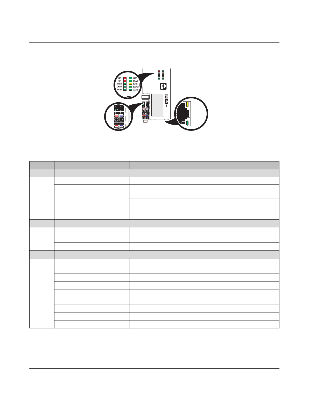
DIAG Green on Run: Cyclic data exchange; status and data from the higher-level system
is transmitted
Green flashing Active: Configuration is active; data exchange with invalid process data;
channel diagnostics available
Yellow on Ready: Device is ready to operate; no data is exchanged
Yellow flashing Access from DTM; DTM accessing bus coupler
Yellow/red flashing Access from DTM, device is in force mode
Red flashing Local bus error on startup with possible causes:
- Information is missing from a device and preventing configuration.
- Desired and actual configurations are different.
- No local bus device connected.
- Maximum number of local bus devices exceeded.
Red on Local bus error with possible causes:
- Communication error.
- Local bus device removed or configured device missing.
- Reset at a local bus device.
- Serious device error at a local bus device (local bus device can no
longer be reached).
Error
ERROR Yellow on I/O warning at a local bus device; Diagnostic alarm triggered
Red on I/O error at a local bus device; PROFIBUS communications failure; No
cyclic data
LNK1 Green on Backplane Ethernet port 1 link
ACT 1 Green flashing Backplane Ethernet port 1 activity
LNK2 Green on Backplane Ethernet port 2 link
ACT 2 Green flashing Backplane Ethernet port 2 activity
Device status
PRIM Green on Functioning and waiting for commissioning
Green flashing Commissioned and cycling data
Red on No redundancy
Yellow on Backup status
Yellow flashing Backup commissioned and cycle data
Table 2-1 AXL P BK PN AF LEDs
Label Color Description

Axioline P
8/16 PHOENIX CONTACT 4028_en_A
2.1.2 Indicators on fieldbus power supplies
Figure 2-2 LEDs on the AXL P FBPS BASE and AXL P FBPS 28DC/0.5A
AXL P FBPS BASE
Ord. No. 2316393
SS
—
+
P-P+
P-P+
UL
DC OK
RDNT
STATUS
ERROR
DC OK
RDNT
STATUS
ERROR
DC OK
RDNT
STATUS
ERROR
P-P+
P-P+
SS
—
+
UL
Table 2-2 AXL P FBPS BASE and AXL P FBPS 28DC/0.5A LEDs
Label Color Description
DC OK Green on DC output voltage is >26 V DC
Yellow on DC input voltage is <26 V DC
Red on Plug failure - undefined status
Off (all LEDs) Input voltage <10 V DC or plug failure
RDNT Green on Load sharing with two plugs: >27.19 V DC; current <500 mA
Yellow on Plug failure - undefined status
Red on Redundant output: <27.19 V DC; >500 mA
STATUS Green on Primary status
Yellow on Secondary status
Red on Fault - Unable to initialize as primary or secondary
Off (all LEDs) Idle
ERROR Green on Retries of any PROFIBUS PA device <3 per minute
Yellow on I/O warning - Retries of any PROFIBUS PA device >3 per minute
Red on I/O error - One or more PROFIBUS PA devices missing from Live List

Diagnostics in the Axioline P system
4028_en_A PHOENIX CONTACT 9/16
2.2 Channel error types and DTM diagnostics
The AXL P... system is designed to include integrated physical layer diagnostics of the
PROFIBUS PA segments in the FBPS plugs. These physical layer diagnostics can be
interpreted through the LEDs on the FBPS plugs as well as in further detail in the DTM.
Table 2-3 shows the available physical layer and NE 107 diagnostics available in the power
supply plugs.
Table 2-3 DTM diagnostics for the AXL P BK PN AF bus coupler
Channel error types and DTM diagnostics
(0x0001... 0x001F & 0x0100... 0x7FFF)
Manufacturer specific alarms (0x0000 ... 0x007F)
Manufacturer specific DAP indexes (0x0000 ... 0x7FFF)
Manufacturer specific FAP indexes (0x0000 ... 0x7FFF)
Type # Limit (if
applicable)
NE 107 state
showing default
designation and
color code
Undervoltage 0x0002 Failure (F)
Overvoltage 0x0003 Failure (F)
Overtemperature 0x0005 95°C Failure (F)
PROFINET parameterization fault 0x0100 (256) Failure (F)
Power supply fault -> backplane power fault 0x0101 (257) Failure (F)
System addressing failed 0x0103 (259) Failure (F)
Left terminator missing 0x0104 (260) Failure (F)
Right terminator missing 0x0105 (261) Failure (F)
No functional I/O module detected 0x0106 (262) Failure (F)
Backplane communication error with more than one functional I/O
module (CAN)
0x0107 (263) Failure (F)
Maximum number of functional I/O modules exceeded 0x0108 (264) Failure (F)
Configuration mismatch 0x010A (266) Failure (F)
BK firmware upgrade & log retrieval 0x010C (268)
BK FW upgrade error - FTP Server
BK FW upgrade error - FW image update determination
BK FW upgrade error - partition determination
BK FW upgrade error - process FW upload file
BK FW upgrade error - FW upload decompression
BK FW upgrade error - individual file verification
BK FW upgrade error - flash memory programming
BK FW upgrade error - flash memory image validation
BK FW upgrade error - bootloader update
BK FW upgrade error - FTP Server
BK is not redundant if the system has been configured for R1 or R2
redundancy
0x010D (269) Maintenance (Priority
High)
Manufacturer’s specific alarms 0x010E (270) Maintenance (Priority
High)

Axioline P
10/16 PHOENIX CONTACT 4028_en_A
Table 2-4 DTM diagnostics for the Axioline P power supply (0x0140 … 0x0180)
Channel error types and DTM diagnostics
(0x0001... 0x001F & 0x0100... 0x7FFF)
Manufacturer specific alarms (0x0000 ... 0x007F)
Manufacturer specific DAP indexes (0x0000 ... 0x7FFF)
Manufacturer specific FAP indexes (0x0000 ... 0x7FFF)
Type # Limit (if
applicable)
NE 107 state
showing default
designation and
color code
PRM fault (PB) (PA device fault) 0x0140 (320) Failure (F)
Config fault (PB) (PA device fault) 0x0141 (321) Failure (F)
FB power supply low output voltage - minimum specified limit 0x0142 (322) 9 V Out of specification
(S)
FB power supply high output voltage - maximum specified limit 0x0143 (323) 32 V Out of specification
(S)
FB power supply maximum output current exceeded - maximum
specified limit
0x0144 (324) 600 mA Out of specification
(S)
FB power supply loss of redundancy 0x0145 (325) Maintenance (Priority
High)
Number of retries an any fieldbus device >3 per minute
Raised at the PB slave slot, not the FAP slot
0x0146 (326) 3 Maintenance (Priority
High)
Loss of fieldbus communication on one or more channels 0x0147 (327) Failure (F)
PA power supply firmware upgrade 0x0148 (328) Failure (F)
FB power supply low output voltage - user setting 0x0149 (329) 24 V Maintenance (Priority
Low)
FB power supply high output voltage - user setting 0x014A (330) 30 V Maintenance (Priority
Low)
FB power supply max output current exceeded - user setting 0x0149 (329) 500 mA Maintenance (Priority
Low)
Shield short 0x014C (332) Maintenance (Priority
Low)
FB power supply (-) to shield short
FB power supply (+) to shield short
FB power supply intermittent shield short to (-)
FB power supply intermittent shield short to (+)
No short detected

List of tables
4028_en_A PHOENIX CONTACT 13/16
A 2 List of tables
Section 2
Table 2-1: AXL P BK PN AF LEDs.......................................................................... 6
Table 2-2: AXL P FBPS BASE and AXL P FBPS 28DC/0.5A LEDs........................ 8
Table 2-3: DTM diagnostics for the AXL P BK PN AF bus coupler.......................... 9
Table 2-4: DTM diagnostics for the Axioline P power supply (0x0140 … 0x0180) 10

PHOENIX CONTACT 15/16
Please observe the following notes
General terms and conditions of use for technical documentation
Phoenix Contact reserves the right to alter, correct, and/or improve the technical
documentation and the products described in the technical documentation at its own
discretion and without giving prior notice, insofar as this is reasonable for the user. The
same applies to any technical changes that serve the purpose of technical progress.
The receipt of technical documentation (in particular user documentation) does not
constitute any further duty on the part of Phoenix Contact to furnish information on
modifications to products and/or technical documentation. You are responsible to verify the
suitability and intended use of the products in your specific application, in particular with
regard to observing the applicable standards and regulations. All information made
available in the technical data is supplied without any accompanying guarantee, whether
expressly mentioned, implied or tacitly assumed.
In general, the provisions of the current standard Terms and Conditions of Phoenix Contact
apply exclusively, in particular as concerns any warranty liability.
This manual, including all illustrations contained herein, is copyright protected. Any
changes to the contents or the publication of extracts of this document is prohibited.
Phoenix Contact reserves the right to register its own intellectual property rights for the
product identifications of Phoenix Contact products that are used here. Registration of such
intellectual property rights by third parties is prohibited.
Other product identifications may be afforded legal protection, even where they may not be
indicated as such.

PHOENIX CONTACT GmbH & Co. KG • Flachsmarktstraße 8 • 32825 Blomberg • Germany
phoenixcontact.com
16/16
16
How to contact us
Internet Up-to-date information on Phoenix Contact products and our Terms and Conditions can be
found on the Internet at:
phoenixcontact.com
Make sure you always use the latest documentation.
It can be downloaded at:
phoenixcontact.net/products
Subsidiaries If there are any problems that cannot be solved using the documentation, please contact
your Phoenix Contact subsidiary.
Subsidiary contact information is available at phoenixcontact.com.
Published by PHOENIX CONTACT GmbH & Co. KG
Flachsmarktstraße 8
32825 Blomberg
GERMANY
PHOENIX CONTACT Development and Manufacturing, Inc.
586 Fulling Mill Road
Middletown, PA 17057
USA
Should you have any suggestions or recommendations for improvement of the contents and
layout of our manuals, please send your comments to:
tecdoc@phoenixcontact.com
Other manuals for Axioline P
1
Table of contents