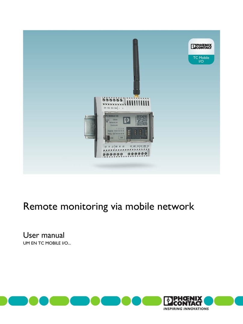
Phoenix Contact TC MOBILE I/O X200 User manual

User manual
TC MOBILE I/O...
Remote monitoring via mobile
network
iOS Android

2017-04-24
PHOENIX CONTACT 107812_en_00
TC MOBILE I/O...
Remote monitoring via mobile network
UM EN TC MOBILE I/O...
00
Designation Revision Order No.
TC MOBILE I/O X200 2903805
TC MOBILE I/O X300 2903807
TC MOBILE I/O X200 AC 2903806
TC MOBILE I/O X300 AC 2903808
User manual
Designation:
Revision:
This user manual is valid for:

PHOENIX CONTACT
Please observe the following notes
User group of this manual
The use of products described in this manual is oriented exclusively to qualified electricians
or persons instructed by them, who are familiar with applicable standards and other
regulations regarding electrical engineering and, in particular, the relevant safety concepts.
Explanation of symbols used and signal words
How to contact us
Internet Up-to-date information on Phoenix Contact products and our Terms and Conditions can be
found on the Internet at:
phoenixcontact.com
Make sure you always use the latest documentation.
It can be downloaded at:
phoenixcontact.net/products
Subsidiaries If there are any problems that cannot be solved using the documentation, please contact
your Phoenix Contact subsidiary.
Subsidiary contact information is available at phoenixcontact.com.
Published by PHOENIX CONTACT GmbH & Co. KG
Flachsmarktstraße 8
32825 Blomberg
GERMANY
Should you have any suggestions or recommendations for improvement of the contents and
layout of our manuals, please send your comments to:
tecdoc@phoenixcontact.com
This is the safety alert symbol. It is used to alert you to potential personal injury
hazards. Obey all safety measures that follow this symbol to avoid possible
injury or death.
There are three different categories of personal injury that are indicated with a
signal word.
DANGER This indicates a hazardous situation which, if not avoided, will
result in death or serious injury.
WARNING This indicates a hazardous situation which, if not avoided, could
result in death or serious injury.
CAUTION This indicates a hazardous situation which, if not avoided, could
result in minor or moderate injury.
This symbol together with the signal word NOTE and the accompanying text
alert the reader to a situation which may cause damage or malfunction to the
device, hardware/software, or surrounding property.
This symbol and the accompanying text provide the reader with additional
information or refer to detailed sources of information.

Please observe the following notes
PHOENIX CONTACT
General terms and conditions of use for technical documentation
Phoenix Contact reserves the right to alter, correct, and/or improve the technical
documentation and the products described in the technical documentation at its own
discretion and without giving prior notice, insofar as this is reasonable for the user. The
same applies to any technical changes that serve the purpose of technical progress.
The receipt of technical documentation (in particular user documentation) does not
constitute any further duty on the part of Phoenix Contact to furnish information on
modifications to products and/or technical documentation. You are responsible to verify the
suitability and intended use of the products in your specific application, in particular with
regard to observing the applicable standards and regulations. All information made
available in the technical data is supplied without any accompanying guarantee, whether
expressly mentioned, implied or tacitly assumed.
In general, the provisions of the current standard Terms and Conditions of Phoenix Contact
apply exclusively, in particular as concerns any warranty liability.
This manual, including all illustrations contained herein, is copyright protected. Any
changes to the contents or the publication of extracts of this document is prohibited.
Phoenix Contact reserves the right to register its own intellectual property rights for the
product identifications of Phoenix Contact products that are used here. Registration of such
intellectual property rights by third parties is prohibited.
Other product identifications may be afforded legal protection, even where they may not be
indicated as such.

107812_en_00 PHOENIX CONTACT 5
Table of contents
1 For your safety ...........................................................................................................................7
1.1 Intended use.......................................................................................................... 7
1.2 Warning instructions.............................................................................................. 7
1.3 Installation notes.................................................................................................... 8
1.4 Installation in zone 2 .............................................................................................. 9
2 Installation ................................................................................................................................11
2.1 Product description.............................................................................................. 11
2.2 Unpacking ........................................................................................................... 14
2.3 Mounting ............................................................................................................. 14
2.4 Connecting the antenna ...................................................................................... 16
2.5 Inserting the SIM card.......................................................................................... 16
2.6 Wiring .................................................................................................................. 17
2.7 Removal .............................................................................................................. 21
3 Configuration ...........................................................................................................................23
3.1 Communication channels TC MOBILE I/O X200... .............................................. 24
3.2 Communication with an ODP server with TC MOBILE I/O X300..........................27
3.3 Unsupported PCP channels ................................................................................ 27
3.4 Configuration....................................................................................................... 28
4 Detecting and removing errors .................................................................................................37
4.1 Initial installation does not start automatically (Windows®).................................. 37
4.2 Access via the web browser is not possible.........................................................38
4.3 The content is not correctly displayed in the web browser...................................42
5 Technical data .........................................................................................................................45
5.1 Ordering data ...................................................................................................... 45
5.2 Accessories......................................................................................................... 45
5.3 Comparison of product features ..........................................................................47
5.4 Technical data ..................................................................................................... 49
5.5 Conformance....................................................................................................... 52
A FCC approval............................................................................................................................55
B Appendixes...............................................................................................................................57
B 1 List of figures ....................................................................................................... 57
B 2 Index.................................................................................................................... 59
TC MOBILE I/O...
6PHOENIX CONTACT 107812_en_00

For your safety
107812_en_00 PHOENIX CONTACT 7
1Foryoursafety
1.1 Intended use
The TC MOBILE I/O... devices monitor digital values via the mobile network and switch
relay outputs. The data is transmitted depending on series via SMS, e-mail or the ODP pro-
tocol.
1.2 Warning instructions
Only for the DC devices TC MOBILE I/O X200 and TC MOBILE I/O X300:
Only for the AC devices TC MOBILE I/OX200 AC and TC MOBILE I/O X300 AC:
Operation of the wireless system is only permitted if accessories available from Phoenix
Contact are used. The use of other accessory components could invalidate the operating
license. You can find the approved accessories for this wireless system listed with the
product at phoenixcontact.net/products.
WARNING: Risk of electric shock
During operation, certain parts of this device may carry hazardous voltages. Disregarding
this warning may result in property damage and/or serious personal injury.
– Provide overcurrent protection (I ≤6 A) within the installation.
– The power output of the power supply unit must not exceed 240 VA.
WARNING: Risk of electric shock
During operation, certain parts of this device may carry hazardous voltages. Disregarding
this warning may result in property damage and/or serious personal injury.
– Never carry out work on live parts.
– This device is not suitable for monitoring sensitive systems or time-critical processes.
GSM network failures or power supply interruptions may adversely affect monitoring.
– The device is intended for installation in a control cabinet or a comparable container.
The device may only be operated when it has been installed. The control cabinet
must meet the requirements of EN/IEC 60950-1 in terms of fire protection shielding.
Additionally, it must provide adequate protection against electric shock (protection
against contact).
– It must be possible to disconnect the device from the power supply. Install an appro-
priate disconnecting device (fuse, miniature circuit breaker, etc.) for this purpose.
– During electrical installation, observe the current standards and regulations. Installa-
tion must be carried out by an expert.

TC MOBILE I/O...
8PHOENIX CONTACT 107812_en_00
1.3 Installation notes
•The category 3 device is designed for installation in Zone 2 potentially explosive areas.
It meets the requirements of EN 60079-0:2012+A11:2013 and EN 60079-15:2010.
•Installation, operation, and maintenance must be carried out by qualified electricians.
Follow the installation instructions as described. When installing and operating the de-
vice, the applicable regulations and safety directives (including national safety direc-
tives), as well as the general codes of practice, must be observed. The safety data is
provided in the packing slip and on the certificates (conformity assessment, additional
approvals where applicable).
•Do not open or modify the device. Do not repair the device yourself; replace it with an
equivalent device instead. Repairs may only be carried out by the manufacturer. The
manufacturer is not liable for damages resulting from noncompliance.
•The IP20 degree of protection (IEC 60529/EN 60529) of the device is intended for use
in a clean and dry environment. Do not subject the device to mechanical and/or thermal
loads that exceed the specified limits.
•The device is not suitable for installation in zone 22.
•If, however, you wish to use the device in zone 22, it must be installed in housing that
complies with IEC/EN 60079-31. In doing so, observe the maximum surface tempera-
tures. Observe the requirements of IEC/EN 60079-14.
WARNING:
Observe the following safety notes when using the device.

For your safety
107812_en_00 PHOENIX CONTACT 9
1.4 Installation in zone 2
•Observe the specified conditions for use in potentially explosive areas!
•Install the device in a suitable, approved housing (with at least IP54 protection) that
meets the requirements of EN 60079-15. For this purpose, observe the requirements of
IEC 60079-14 / EN 60079-14.
•Only connect devices to the supply and signal circuits in Zone 2 that are suitable for op-
eration in Ex Zone 2 and for the conditions at the installation location.
•In potentially explosive areas, only connect and disconnect cables when the power is
disconnected.
•Replace the SIM card only when the power is disconnected.
•The configuration interface may only be used if it has been ensured that there is no po-
tentially explosive atmosphere present.
•The switches of the device that can be accessed may only be actuated when the power
supply to the device is disconnected.
•Observe the derating information in the technical documentation.
•All plug connections must be completely plugged in and, if possible, screwed tightly
and/or locked.
•The device must be stopped and immediately removed from the Ex area if it is dam-
aged, was subjected to an impermissible load, stored incorrectly or if it malfunctions.
•Ensure that the radiated wireless power is neither bundled (focused) by the antenna it-
self nor by any inserts in the environment of the antenna, and that it cannot enter neigh-
boring Zones 1 or 0. Please refer to the technical data for the HF output power. It must
not exceed 2 W.
•The HF cable to the antenna must be suitable for the ambient conditions. Install the ca-
ble so that it is protected against mechanical damage, corrosion, chemical stress, and
negative effects from heat or UV radiation. The same applies to the antenna which is
connected to the cable and which functions as a cable termination.
•The antenna itself must meet the relevant requirements of EN 60079-0.
WARNING: Explosion hazard when used in potentially explosive areas
Make sure that the following notes and instructions are observed and complied with.

TC MOBILE I/O...
10 PHOENIX CONTACT 107812_en_00

Installation
107812_en_00 PHOENIX CONTACT 11
2 Installation
2.1 Product description
The compact TC MOBILE I/O...signaling system monitors analog and digital values via the
mobile network. It also switches relay outputs remotely.
The device offers numerous helpful software functions, such as mobile communication di-
agnostics and different user roles. A USB connection to a computer with a web browser is
all that is needed for configuration.
Applications
– Machine, building, and system monitoring
– Pumps, wastewater treatment plants, water supply
– Lighting control systems, remote switchgear
– Elevators, gates
– Alarm technology and building services
–HVACtechnology
– Battery monitoring (up to 60 V)
– Railway applications (according to EN 50121-4)
Features
– GSM mobile network: 850, 900, 1800, and 1900 MHz
– Event-controlled or interval-controlled communication
– Four digital inputs
– Four relay outputs, can be switched via mobile network
– DC versions: two scalable analog inputs, can be switched between current and voltage
– Standard mini SIM card
– Compact design: 4 div. in acc. with DIN 43880
– Housing cover, can be sealed
– Mounting on DIN rail or on the wall
– SMS alerts in the event of voltage failure
– Approval for Ex zone 2 (nA, nC)
Table 2-1 Product versions
Designation Order
No.
Voltage range Communication
TC MOBILE I/O X200 2903805 10 V ... 60 V DC – SMS
–E-mail
– App (SMS, HTTPS)
TC MOBILE I/OX200 AC 2903806 93 V ... 250 V AC
TC MOBILE I/O X300 2903807 10 V ... 60 V DC – ODP protocol
TC MOBILE I/O X300 AC 2903808 93 V ... 250 V AC
You can find a detailed overview of the product versions under “Comparison of product
features” on page 47.

TC MOBILE I/O...
12 PHOENIX CONTACT 107812_en_00
2.1.1 TC MOBILE I/O X200 and TC MOBILE I/O X300
TC MOBILE
SIM
Network
Device
Reset
USB SIM
1234
Digital IN
Relay OUT
Documentation
TC MOBILE I/O
X200
Ord.-No.:
2903806
DI1 DI2 DI3 DI4
+
-
U1 I1 U2 I2
12O1 UB1 O2 O1 UB1 O2
12
3
4
5
6
7
8
9
10 11 12 13
15
1617
14
0,5-0,6 Nm
5-7 lb In
Operating elements and LEDs
124 V DC supply voltage
2DI1 ... DI4 Digital inputs
3SIM Green on SIM card ready to operate
Orange on SIM card not inserted
Flashing orange Mobile engine awaits PIN, PUK, or a different password
Red on SIM card fault
4Network Green on Connection present, very good field strength
Orange on Sufficient field strength
Flashing orange Poor field strength
Red on No connection
5Reset button Hold down for three seconds to reset the device to the default settings
6Device Green on Power supply via power supply unit
Orange on Power supply only via USB
Flashing orange Firmware update
Red on Hardware fault
7Digital IN Green on High level at the input
Green off Low level at the input
8USB interface Only for configuration
9OUT relay Green on Relay picked up, switch contact closed
Green off Relay dropped out, switch contact open
10 Analog input 1 Can be switched between current and voltage
11 Analog input 2 Can be switched between current and voltage
12 Relay 1 + 2 (N/O contact)
13 Relay 3 + 4 (N/O contact)
14 Lugs for closing the housing cover
15 Mini SIM card
16 SMA antenna connection (socket)
17 Extendable base latch for wall mounting

Installation
107812_en_00 PHOENIX CONTACT 13
2.1.2 TC MOBILE I/OX200 AC and TC MOBILE I/O X300 AC
0,5-0,6 Nm
5-7 lb In
TC MOBILE
SIM
Network
Device
Reset
USB SIM
1234
Digital IN
Relay OUT
Documentation
TC MOBILE I/O
X200
Ord.-No.:
2903806
NL
ND ND DI1 DI2 DI3 DI4 O1 UB1 O2 O1 UB1 O2
1
2
3
4
5
6
7
8
9
10 11 12 13
15
14
1617
Operating elements and LEDs
1L230 V AC supply voltage
2N
3SIM Green on SIM card ready to operate
Orange on SIM card not inserted
Flashing orange Mobile engine awaits PIN, PUK, or a different password
Red on SIM card fault
4Network Green on Connection present, very good field strength
Orange on Sufficient field strength
Flashing orange Poor field strength
Red on No connection
5Reset button Hold down for three seconds to reset the device to the default settings
6Device Green on Power supply via power supply unit
Orange on Power supply only via USB
Flashing orange Firmware update
Red on Hardware fault
7Digital IN Green on High level at the input
Green off Low level at the input
8USB interface Only for configuration
9OUT relay Green on Relay picked up, switch contact closed
Green off Relay dropped out, switch contact open
10 ND Neutral conductor
11 DI1 ... DI4 Digital inputs
12 Relay 1 + 2 (N/O contact)
13 Relay 3 + 4 (N/O contact)
14 Lugs for closing the housing cover
15 Mini SIM card
16 SMA antenna connection (socket)
17 Extendable base latch for wall mounting

TC MOBILE I/O...
14 PHOENIX CONTACT 107812_en_00
2.2 Unpacking
•Take the device out of its packaging.
•Check the device for damage in transit.
•Retain the packing slip for future use.
•Dispose of packaging in an environmentally-friendly way.
2.3 Mounting
2.3.1 DIN rail
•Use a grounding terminal block to connect a 35 mm EN DIN rail to a protective earth
ground. The module is grounded by snapping it onto the DIN rail.
•Place the device onto the DIN rail from above.
•Push the front of the device toward the mounting surface until it audibly snaps into
place.
Figure 2-1 DIN rail mounting
WARNING: Risk of electric shock
Only mount or remove the device when disconnected from the voltage.

Installation
107812_en_00 PHOENIX CONTACT 15
2.3.2 Wall
On the back of the device there are two removable base latches for wall mounting.
•Push the snap-in latch downwards with a screwdriver and pull out the base latch.
•Insert a washer between the extracted base latch and the level sub base.
•Secure the device to the wall using the screws.
– Maximum thread diameter 4 mm
– Maximum head diameter 8.5 mm
Figure 2-2 Wall mounting
A B

TC MOBILE I/O...
16 PHOENIX CONTACT 107812_en_00
2.4 Connecting the antenna
The antenna is not supplied as standard. We recommend using the following antennas:
– PSI-GSM/UMTS-QB-ANT (Order No. 2313371) or
– TC ANT MOBILE WALL 5M (Order No. 2702273)
•Screw the antenna on to the device.
2.5 Inserting the SIM card
•Open the housing cover.
•Push the SIM card cover to the right and open it.
•Slide the SIM card into the holder with the contact surface facing down. Note the posi-
tion of the diagonal corner.
•Close the SIM card cover. Push it to the left.
•Close the housing cover.
•Protect the SIM card with a multi-digit PIN code.
Figure 2-3 Inserting the SIM card
NOTE: Device damage
Disconnect the device power supply before replacing the SIM card
SIM
Network
Device
Reset
USB SIM
1234
lay OUT
Documentation
TCMOBILEI/O
X200
Re
Digita
AB
SIM
Network
Device
Reset
USB SIM
1234
lay OUT
Documentation
TCMOBILEI/O
X200
Re
Digita
C

Installation
107812_en_00 PHOENIX CONTACT 17
2.6 Wiring
2.6.1 DC devices: TC MOBILE I/O X200 and TC MOBILE I/O X300
•Connect the device.
Figure 2-4 Supply voltage 10 V DC ... 60 V DC, digital inputs
Figure 2-5 Relay outputs (DC devices)
Railway applications in accordance with EN 50121-4 outside the 3 m range:
Use QUINT POWER power supplies from PhoenixContact directly on the device. Supply
voltage to the device via terminals.
WARNING: Risk of electric shock
During operation, certain parts of this device may carry hazardous voltages. Disregarding
this warning may result in property damage and/or serious personal injury.
– Provide overcurrent protection (I ≤6 A) within the installation.
– The output power of the power supply unit must not exceed 240 VA.
NOTE: Device damage
Always connect the voltage source to the center contact of the relay (UB1, UB2) and the
load to the N/O contact (O1, O2, O3, O4).
DI1 DI2DI3DI4
+
-
0V
24V
O1 UB1 O2
L
N

TC MOBILE I/O...
18 PHOENIX CONTACT 107812_en_00
Figure 2-6 Analog inputs (DC devices)
= Ground
The analog inputs, can be switched between
–Current:I1and1
– Voltage: U1 and 1 or supply earth
TC MO
USB SIM
U1 I1 U2 I2
12
10 11

Installation
107812_en_00 PHOENIX CONTACT 19
2.6.2 AC devices: TC MOBILE I/OX200 AC and
TC MOBILE I/O X300 AC
•Connect the device.
Figure 2-7 Supply voltage: 93 V AC ... 250 V AC
Figure 2-8 Digital inputs (AC devices)
WARNING: Risk of electric shock
During operation, certain parts of this device may carry hazardous voltages. Disregarding
this warning may result in property damage and/or serious personal injury.
– Never carry out work on live parts.
– This device is not suitable for monitoring sensitive systems or time-critical processes.
GSM network failures or power supply interruptions may adversely affect monitoring.
– The device is intended for installation in a control cabinet or a comparable container.
The device may only be operated when it has been installed. The control cabinet
must meet the requirements of EN/IEC 60950-1 in terms of fire protection shielding.
Additionally, it must provide adequate protection against electric shock (shock pro-
tection).
– It must be possible to disconnect the device from the power supply. Install an appro-
priate disconnecting device (fuse, miniature circuit breaker, etc.) for this purpose.
– During electrical installation, observe the current standards and regulations. Installa-
tion must be carried out by an expert.
WARNING: Danger to life by electric shock!
No voltage above 230 V AC must occur at the device itself. Ensure that all signals and the
supply voltage refer to the same neutral conductor.
NL
N
L
ND ND DI1 DI2DI3DI4
ND
L3
L2
L1

TC MOBILE I/O...
20 PHOENIX CONTACT 107812_en_00
Figure 2-9 Relay outputs (AC devices)
NOTE: Device damage
Always connect the voltage source to the center contact of the relay (UB1, UB2) and the
load to the N/O contact (O1, O2, O3, O4).
O1 UB1 O2
L
N
This manual suits for next models
7
Table of contents
Other Phoenix Contact Measuring Instrument manuals

Phoenix Contact
Phoenix Contact TESTFOX CC User manual

Phoenix Contact
Phoenix Contact TC MOBILE I/O Series User manual

Phoenix Contact
Phoenix Contact EMpro EEM-MA370 User manual

Phoenix Contact
Phoenix Contact EMpro EEM-MA400 Quick start guide

Phoenix Contact
Phoenix Contact EMpro EEM-MA371 Quick start guide

Phoenix Contact
Phoenix Contact SCK-C-MODBUS User manual

Phoenix Contact
Phoenix Contact EEM-MA200 User manual

Phoenix Contact
Phoenix Contact Axioline F User manual

Phoenix Contact
Phoenix Contact LM-S User manual