Phoenix Contact IB IL 24 AI 2/SF-230 User manual

6232A 1
IB IL 24 AI 2/SF-230
01/2001
Data Sheet 6232A
This data sheet is only valid in
association with the
IB IL SYS PRO UM E "Configuring
and Installing the INTERBUS Inline
Product Range" User Manual.
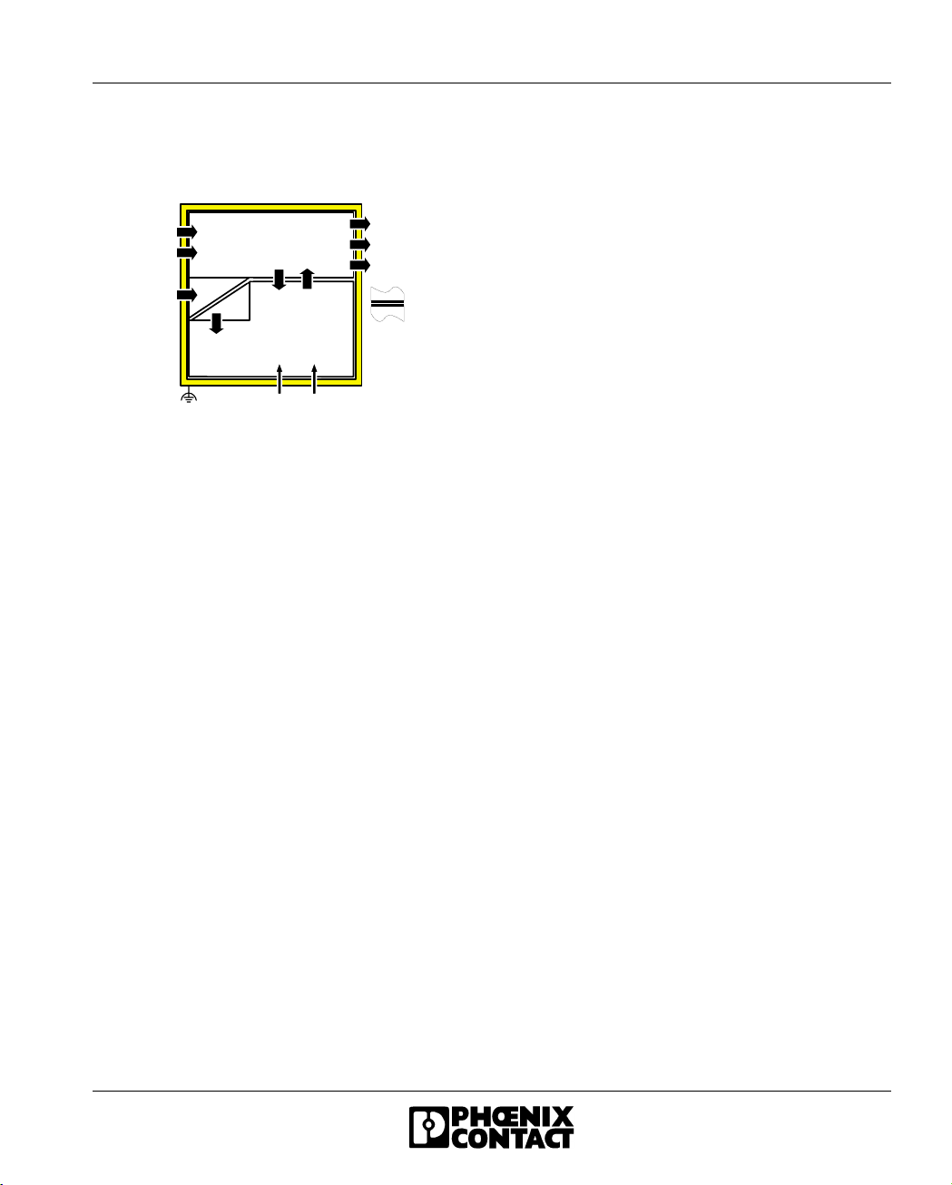
Function
The terminal is designed for use within an
INTERBUS Inline station. It is used to measure
analog voltage or current signals.
Features
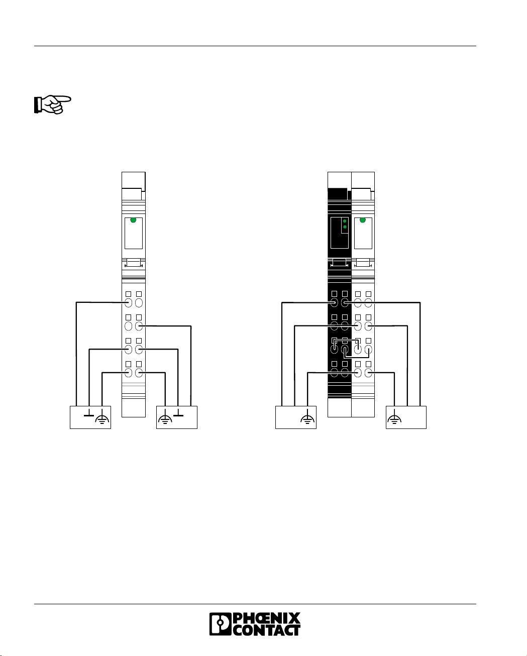
– Two analog single-ended signal inputs for
the connection of either voltage or current
signals
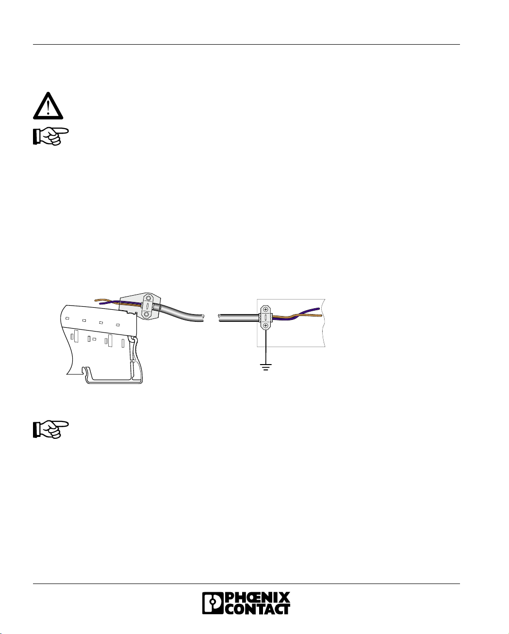
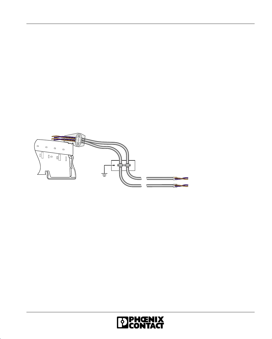
– Connection of sensors in 2- and 3-wire
technology
– Three current measuring ranges:
0 mA through 20 mA, ±20 mA, 4 mA through
20 mA
– Two voltage measuring ranges:
0 V through 10 V, ±10 V
– Configuration of the independent channels
through INTERBUS
– Measured values can be represented in four
different formats
– Resolution independent of the
representation format and the measuring
range
– Process data update of both channels in
1.5 ms, maximum
– Diagnostic indicator
– 230 Hz input filter
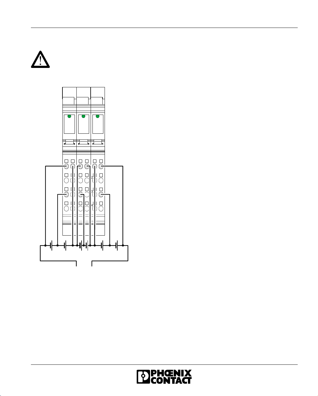
Figure 1 IB IL 24 AI 2/SF-230 terminal
with connector
Please note that the connector is not
supplied as standard with the
terminal. Please refer to the ordering
data on page 31 to order the
appropriate connectors for your
application.
6 2 3 2 A 0 0 2
6 2 3 2 A 0 0 1
INTERBUS Inline Terminal
With Two Analog Input Channels

IB IL 24 AI 2/SF-230
26232A
Table of Contents
Function ...........................................................................................................................................1
Installation Instructions .....................................................................................................................3
Internal Circuit Diagram ...................................................................................................................4
Electrical Isolation ............................................................................................................................5
Connection Notes .............................................................................................................................6
Connection Examples ......................................................................................................................8
Programming Data .........................................................................................................................10
INTERBUS Process Data Words ...................................................................................................11
Formats for Representing the Measured Values ...........................................................................16
Technical Data ...............................................................................................................................25
Ordering Data .................................................................................................................................31

IB IL 24 AI 2/SF-230
6232A 3
Figure 2 IB IL 24 AI 2/SF-230 terminal
with the appropriate connector
Local Diagnostic and Status Indicators
Terminal Assignment
Installation Instructions
High current flowing through the voltage jumpers UMand USleads to a temperature rise of the voltage
jumpers and the inside of the terminal. Note the following instructions to keep the current flowing
through the voltage jumpers of the analog terminals as low as possible:
All of the analog terminals need a separate main circuit.
If this is not possible in your application and if you are using analog terminals in a main
circuit together with other terminals, place the analog terminals behind all the other
terminals at the end of the main circuit.
6 2 3 2 A 0 0 3
D
A I 2 - 2 3 0
1 2
1
2
3
4
1
2
3
4
1 . 1
1 . 2
1 . 3
1 . 4
2 . 1
2 . 2
2 . 3
2 . 4
Des. Color Meaning
DGreen Bus diagnostics
Terminal
Points
Signal Assignment
1.1 +U1 Voltage input channel 1
2.1 +U2 Voltage input channel 2
1.2 +I1 Current input channel 1
2.2 +I2 Current input channel 2
1.3 -1 Return for channel 1
(common for current and
voltage)
2.3 -2 Return for channel 2
(common for current and
voltage)
1.4, 2.4 Shield Shield connection

IB IL 24 AI 2/SF-230
46232A
Internal Circuit Diagram
Figure 3 Internal wiring of the terminal
points
Other symbols are explained in the
IB IL SYS PRO UM E User Manual.
5 5 6 4 A 0 0 3
+ 2 4 V ( U M)
+ 2 4 V ( U S)
I N T E R B U S
O P C
E E P R O M
R E F
2 4 V
+ 5 V
/ + 1 0 V
U
I N
U
I N
I
I N
I
I N
UL +
UA N A
UL -
M U
µ P
1
Key:
Protocol chip
Optocoupler
Power supply unit with electrical
isolation
Microprocessor with multiplexer
and analog/digital converter
Reference voltage
Electrically erasable
programmable read-only memory
Amplifier
Coupling network
OPC
xxx
M U
µ P
R E F
E E P R O M

IB IL 24 AI 2/SF-230
6232A 5
Electrical Isolation
Figure 4 Electrical isolation of the single
function areas
6 2 3 2 A 0 0 4
A n a l o g i n p u t sF E p o t e n t i a l
A
B
E l e c t r i c a l i s o l a t i o n
b e t w e e n a r e a
A a n d B
U
ANA
( 2 4 V D C )
I N T E R B U S
l o c a l b u s ( I N )
I O i n t e r f a c e
a n d
m i c r o p r o c e s s o r
B u s i n t e r f a c e
O P C
I N T E R B U S
l o c a l b u s ( O U T )
U
L
( 7 . 5 V D C )
U
ANA
( 2 4 V D C )
U
L
( 7 . 5 V D C )
2 4 V
5 V
1 0 V
5 V
1 0 V

IB IL 24 AI 2/SF-230
66232A
Connection Notes
Do not connect voltages above ±5 V to a current input. The electronics module will be
damaged if the maximum permissible current of ±100 mA is exceeded.
Always connect analog sensors using twisted and shielded cables (see Figure 5).
Connect the shielding of the terminal using the shield connector clamp. The clamp
connects the shield with high resistance and capacitance to FE on the module side.
Additional wiring is not necessary.
When connecting the sensor shielding with the PE potential, ensure a large surface
connection.
Within the terminal, ground is connected to FE via an RC element.
Figure 5 Connection of analog sensors, signal cables
If you want to use both channels of the IB IL 24 AI 2/SF-230 terminal, you can connect
the shield in various ways depending on the cable feed.
1If one multi-wire cable is used to connect both sensors, connect the shielding as described above
using the shield connector (see Figure 5).
5 5 2 0 0 0 4 3
AB

IB IL 24 AI 2/SF-230
6232A 7
2If two individual cables are used to connect the sensors, proceed as follows to prevent ground
loops (see Figure 6):
•Install a busbar with a connection to the ground potential in front of the Inline terminal (B in
Figure 6). Place the outer sheath of the two cables in the appropriate position and connect
the shields of both cables, e.g., using an SK shield clamp (see "CLIPLINE" Catalog). The
busbar must be the only point at which the shield of every cable is connected with ground
potential.
•Lead the cables to the Inline terminal and connect the shield, as described above, using the
shield connector (A in Figure 6).
•Lead the sensor cable into the sensor making sure to maintain the integrity of the cable
insulation (C in Figure 6).
Figure 6 Connection of two analog sensors with individual cables
5 5 2 0 A 1 1 8
A
B
C

IB IL 24 AI 2/SF-230
86232A
Connection Examples
Use a connector with shield connection when installing the sensors. Figure 7 and Figure 8
show the connection schematically (without shield connector).
Connection of Active Sensors
Figure 7 Connection of active sensors
in 2-wire technology with shield
connection
A Active sensor with voltage output
(channel 1)
B Active sensor with current output (channel 2)
Connection of Passive Sensors
Figure 8 Connection of two passive
sensors in 2-wire technology with
shield connection
Figure 8 shows the passive sensor supply. The
sensors are supplied through a pre-connected
segment terminal with a fuse. The sensors can
also be supplied from an external power supply.
1 2
1
2
3
4
1
2
3
4
D
A I 2 - 2 3 0
6 2 3 2 A 0 0 5
AB
I N
I N
1 2
1
2
3
4
1
2
3
4
U S
U M
S E G / F
1 2
1
2
3
4
1
2
3
4
D
A I 2 - 2 3 0
6 2 3 2 A 0 0 6
I N
2 4 V
I N
2 4 V
I B I L A I 2 / S F - 2 3 0I B I L 2 4 S E G / F

IB IL 24 AI 2/SF-230
6232A 9
Connection for Battery Monitoring
Both reference inputs (minus inputs) of each
IB IL 24 AI 2/SF-230 terminal are connected with each other. If signal sources are
connected in series, wrong connections can lead to a short circuit of individual signal
sources.
Figure 9 Connection for battery monitoring
Because of the single-ended inputs, the
following connections are necessary:
Connect the reference input of a terminal
between two voltage sources.
Channel 1 measures the first voltage source
with opposite polarity. The measured value must
be adapted in the control system to the polarity.
Channel 2 measures the second voltage source
with correct polarity.
Configure the terminal to bipolar (±10 V).
1 2
1
2
3
4
1
2
3
4
D
A I 2 - 2 3 0
1 2
1
2
3
4
1
2
3
4
D
A I 2 - 2 3 0
1 2
1
2
3
4
1
2
3
4
D
A I 2 - 2 3 0
6 2 3 2 A 0 0 7
1 2 V
2 V 2 V 2 V 2 V 2 V 2 V

IB IL 24 AI 2/SF-230
10 6232A
Programming Data
ID code 7Fhex (127dec)
Length code 02hex
Process data channel 32 bits
Input address area 4 bytes
Output address area 4 bytes
Parameter channel
(PCP)
0 bytes
Register length (bus) 4 bytes

IB IL 24 AI 2/SF-230
6232A 11
INTERBUS Process Data Words
Process Data Output Words for the Configuration of the Terminal (see page 13)
Assignment of the Terminal Points to the Process Data Input Words (see page 14)
INTERBUS
reference
Word Word x
Bit 1514131211109876543210
(Byte.bit)
view
Byte Byte 0 Byte 1
Bit 7654321076543210
Channel 1 Assignment 100000Filter 0 0 Format Measuring
range
Channel 2 Assignment 100000Filter 0 0 Format Measuring
range
INTERBUS
reference
Word Word x
Bit 1514131211109876543210
(Byte.bit)
view
Byte Byte 0 Byte 1
Bit 7654321076543210
Channel1 Signal 1514131211109876543210
Terminal point 1.1: voltage input
Terminal point 1.2: current input
Signal reference Terminal point 1.3
Shielding (FE) Terminal point 1.4
Channel2 Signal 1514131211109876543210
Terminal point 2.1: voltage input
Terminal point 2.2: current input
Signal reference Terminal point 2.3
Shielding Terminal point 2.4

IB IL 24 AI 2/SF-230
12 6232A
INTERBUS OUT Process Data Output Words
With the two process data output words you can
configure each channel of the terminal
independently. The following configurations are
possible:
–Selecting a measuring range according to
the input signal
–Switching off mean-value generation
–Changing the formats of the measured value
representation
The configuration setting is not saved. It must be
transmitted in each INTERBUS cycle.
After applying voltage (power up) to the Inline
station, the message "Measured value invalid"
(error code 8004hex) appears in the process
data input words. After 1 s (maximum) the
preset configuration is accepted and the first
measured value is available. If you change the
configuration the corresponding channel is re-
initialized. The message "Measured value
invalid" (error code 8004hex) appears in the
process data output words for 100 ms
(maximum).
Default:
Measuring range: 0 through 10 V
Mean-value generation: Switched on
Output format: IL format
Mean-value generation should be
deactivated for the analysis of
dynamic signals.
You cannot change the signal input
type through the process data output
words. Current or voltage
measurement is selected by applying
the measured signal to the current or
voltage input.
In addition, select the corresponding
measuring range through the process
data output words.
Do not simultaneously apply current
and voltage signals to an input
channel as you will not receive valid
measured values.

IB IL 24 AI 2/SF-230
6232A 13
Figure 10 Process data output words
One process data output word is available for
the configuration of each channel.
Set bit 15 of the corresponding output word to 1
to configure the terminal. If bit 15 = 0 the preset
configuration is active.
Bit 15:
Bit 9 and bit 8: Bit 5 and bit 4:
Bit 3 through bit 0:
MSB Most significant bit LSB Least significant bit
C hannel 1
M S B L S B
01 4 1 3 1 2 1 1 1 0 9 8 7 6 5 4 3 2 1
C hannel 2
55640006
F o r m a t M e a s u r i n g r a n g e
P r o c e s s d a t a w o r d 1 P r o c e s s d a t a w o r d 2
1 5
F i l t e rC o n f i g u r a t i o n
Code Configuration
0 Default
1 Configuration data
Code Filter
00 16-sample mean value (default)
01 Mean-value generation Off
10, 11 Reserved
Code Format
00 IB IL (15 bits) (default)
01 IB ST (12 bits)
10 IB RT (15 bits)
11 Standardized display
Code Measuring Range (Voltage)
0000 0 V through 10 V (default)
0001 ±10 V
0010
through
0111
Reserved
Set all reserved bits to 0.
Code Measuring Range (Current)
1000 0 mA through 20 mA
1001 ±20 mA
1010 4 mA through 20 mA
1011 through
1111
Reserved

IB IL 24 AI 2/SF-230
14 6232A
INTERBUS IN Process Data Input Words
The measured values are transmitted, per channel, through the INTERBUS IN process data input
words to the controller board or the computer.
Figure 11 Sequence of the process data input words in the INTERBUS ring and display of the bits
of the first process data word in different formats
SB Sign bit OC Open circuit
AV Analog value OR Overrange
0/4 Measuring range 4 through 20 mA
MSB Most significant bit LSB Least significant bit
C hannel 1
M S B L S B
C hannel 2
P r o c e s s d a t a w o r d 1 P r o c e s s d a t a w o r d 2
01 4 1 3 1 2 1 1 1 0 9 8 7 6 5 4 3 2 11 5
S B A V
01 4 1 3 1 2 1 1 1 0 9 8 7 6 5 4 3 2 11 5
O R0 / 4 O C
S B A V
S T
I L
R T
S t a n d a r d i z e d
D i s p l a y
F o r m a t :
5564A009

IB IL 24 AI 2/SF-230
6232A 15
The process data formats "IB IL" and "Standardized display" support extended diagnostics. The
following error codes are possible:
Code (hex) Error
8001 Overrange
8002 Open circuit
8004 Measured value invalid/no valid measured value available
8010 Configuration invalid
8040 Module defective
8080 Below range

IB IL 24 AI 2/SF-230
16 6232A
Formats for Representing the Measured Values
"IB IL" Format
The measured value is represented in bits 14 through 0. An additional bit (bit 15) is available as a
sign bit.
This format supports extended diagnostics. Values > 8000hex indicate an error. The error codes are
listed on page 15.
Figure 12 Measured value representation in "IB IL" format (15 bits)
This format is preset (default). To ensure that the terminal can be operated in previously used data
formats, the measured value representation can be switched to different formats.
Significant Measured Values
Some codes are used for diagnostic functions. Therefore, the resolution is not 15 bits but
exactly 14.9886847 bits.
Measuring range 0 mA through 20 mA/0 V through 10 V
SB Sign bit AV Analog value
01 4 1 3 1 2 1 1 1 0 9 8 7 6 5 4 3 2 1
55641008
1 5
S B A V
Input Data Word
(Two’s Complement)
0 mA Through 20 mA
IInput
0 V Through 10 V
UInput
hex dec mA V
8001 Overrange > +21.6746 > +10.837
7F00 32512 +21.6746 +10.837
7530 30000 +20.0 +10.0
0001 1 +0.66667 µA +333.33 µV
0000 0 0 0
0000 0 <0 <0

IB IL 24 AI 2/SF-230
6232A 17
Measuring range -20 mA through +20 mA/-10 V through +10 V
Measuring range 4 mA through 20 mA
Input Data Word
(Two’s Complement)
-20 mA Through +20 mA
IInput
-10 V Through +10 V
UInput
hex dec mA V
8001 Overrange > +21.6746 > +10.837
7F00 32512 +21.6746 +10.837
7530 30000 +20.0 +10.0
0001 1 +0.66667 µA +333.33 µV
0000 -1 0 0
FFFF 0 -0.66667 µA -333.33 µV
8AD0 -30000 -20.0 -10.0
8100 -32000 -21.6746 -10.837
8080 Below range <-21.6746 <-10.837
Input Data Word
(Two’s Complement)
4 mA Through 20 mA
IInput
hex dec mA
8001 Overrange > +21.339733
7F00 32512 +21.339733
7530 30000 +20.0
0001 1 +4.00053333
0000 0 +4.0 through 3.2
8002 Open circuit <+3.2

IB IL 24 AI 2/SF-230
18 6232A
"IB ST" Format
The measured value is represented in bits 14 through 3. The remaining 4 bits are sign bit, measuring
range, and error bits.
This format corresponds to the data format used on INTERBUS ST modules.
Figure 13 Measured value representation in "IB ST" format (12 bits)
Significant Measured Values
Measuring range 0 mA through 20 mA/0 V through 10 V
SB Sign bit OC Open circuit
AV Analog value OR Overrange
0/4 Measuring range 4 through 20 mA
Input Data Word
(Two’s Complement)
0 mA Through 20 mA
IInput
0 V Through 10 V
UInput
hex mA V
7FF9 >21.5 >10.75
7FF8 20.0 through 21.5 10.00 through 10.75
7FF8 19.9951 9.9975
4000 10.0 5.0
0008 0.0048828 0.002441
0000 0 0
01 4 1 3 1 2 1 1 1 0 9 8 7 6 5 4 3 2 1
5 5 6 4 0 0 0 7
1 5
O R0 / 4 O C
S B A V

IB IL 24 AI 2/SF-230
6232A 19
Measuring range -20 mA through +20 mA/-10 V through +10 V
Measuring range 4 mA through 20 mA
Input Data Word
(Two’s Complement)
-20 mA Through +20 mA
IInput
-10 V Through +10 V
UInput
hex mA V
7FF9 >21.5 >10.75
7FF8 20.0 through 21.5 10.00 through 10.75
7FF8 19.9951 9.9975
0008 0.0048828 0.002441
0000 0 0
FFF8 -0.0048828 -0.002441
8000 -20.0 through -21.5 -10.00 through -10.75
8001 <-21.5 <-10.75
Input Data Word
(Two’s Complement)
4 mA Through 20 mA
IInput
hex mA
7FFD >21.5
7FFC 20.0 through 21.5
7FFC 19.9961
000C 4.003906
0004 3.2 through 4.0
0006 < 3.2

IB IL 24 AI 2/SF-230
20 6232A
"IB RT" Format
The measured value is represented in bits 14 through 0. An additional bit (bit 15) is available as a
sign bit.
This format corresponds to the data format used on INTERBUS RT modules.
In this data format error codes or error bits are not defined. Open circuit is indicated through the
positive final value 7FFFhex.
Figure 14 Measured value representation in "IB RT" format (15 bits)
Significant Measured Values
Measuring range 0 mA through 20 mA/0 V through 10 V
SB Sign bit AV Analog value
Input Data Word
(Two’s Complement)
0 mA Through 20 mA
IInput
0 V Through 10 V
UInput
hex mA V
7FFF ≥ 19.999385 ≥ 9.999695
7FFE 19.9987745 9.999939
4000 10.0 5.0
0001 0.6105 µA 305.0 µV
0000 ≤0 ≤0
01 4 1 3 1 2 1 1 1 0 9 8 7 6 5 4 3 2 1
55641008
1 5
S B A V
Table of contents
Popular Terminal Block manuals by other brands

Festo
Festo CPVSC1-EPR Series Assembly instructions

Festo
Festo CPV GE-IB-8 Series manual

Festo
Festo CPX-AB-2-M12-RK-IB Assembly instructions

National Instruments
National Instruments NI SCXI -1339 installation instructions

Allen-Bradley
Allen-Bradley Kinetix 5100 installation instructions

NI
NI PXIe-4300 user guide