23
Contents
General Information.................................................................................... page 2
Designated Use........................................................................................... page 3
®
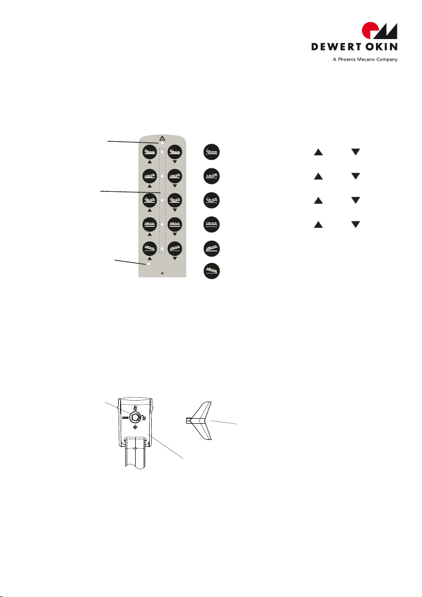
Key Configuration IPROXX SM.................................................................. page 4
®
Function of the Locking Device IPROXX SM............................................. page 4
®
Function Diagram IPROXX SM................................................................. page 5
Function of the Display................................................................................ page 5
Key Configuration page
®
IPROXX SM+............................................................... 6
Function of the Locking Device page
®
IPROXX SM+......................................... . 6
Function Diagram page
®
IPROXX SM+............................................................... 7
Function of the Display page................................................................................ 8
Key Configuration page
®
IPROXX SMP................................................................ 9
Function of the Locking Device page
®
IPROXX SMP........................................... 9
Function Diagram page
®
IPROXX SMP............................................................... 10
Function of the Display page................................................................................ 11
Maintenance and Repairs............................................................................ page 12
Trouble-shooter’s Guide page.............................................................................. 13
Cleaning, Disposal...................................................................................... page 14
EC Declaration of Conformity page...................................................................... 15
General Information
These System Instructions are intended for the manufacturer of the end product and not for
the end user, the latter case requiring Operating Instructions, Directions for Use combined
with the complete drive system.
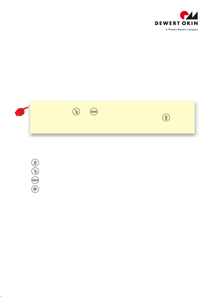
Handset locked (SM/SM+/SMP)
Handset released (SM/SM+/SMP)
Patient functions released (SM+/SMP)
Change Mode for nursing staff / care personnel (SMP)
General symbols on the back of the handset
Note: Keep the handset well away from magnetic objects and strong
magnetic fields. The integrated locking device may accidentally be
activated or deactivated.
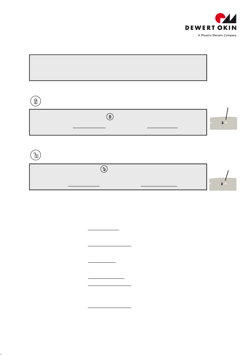
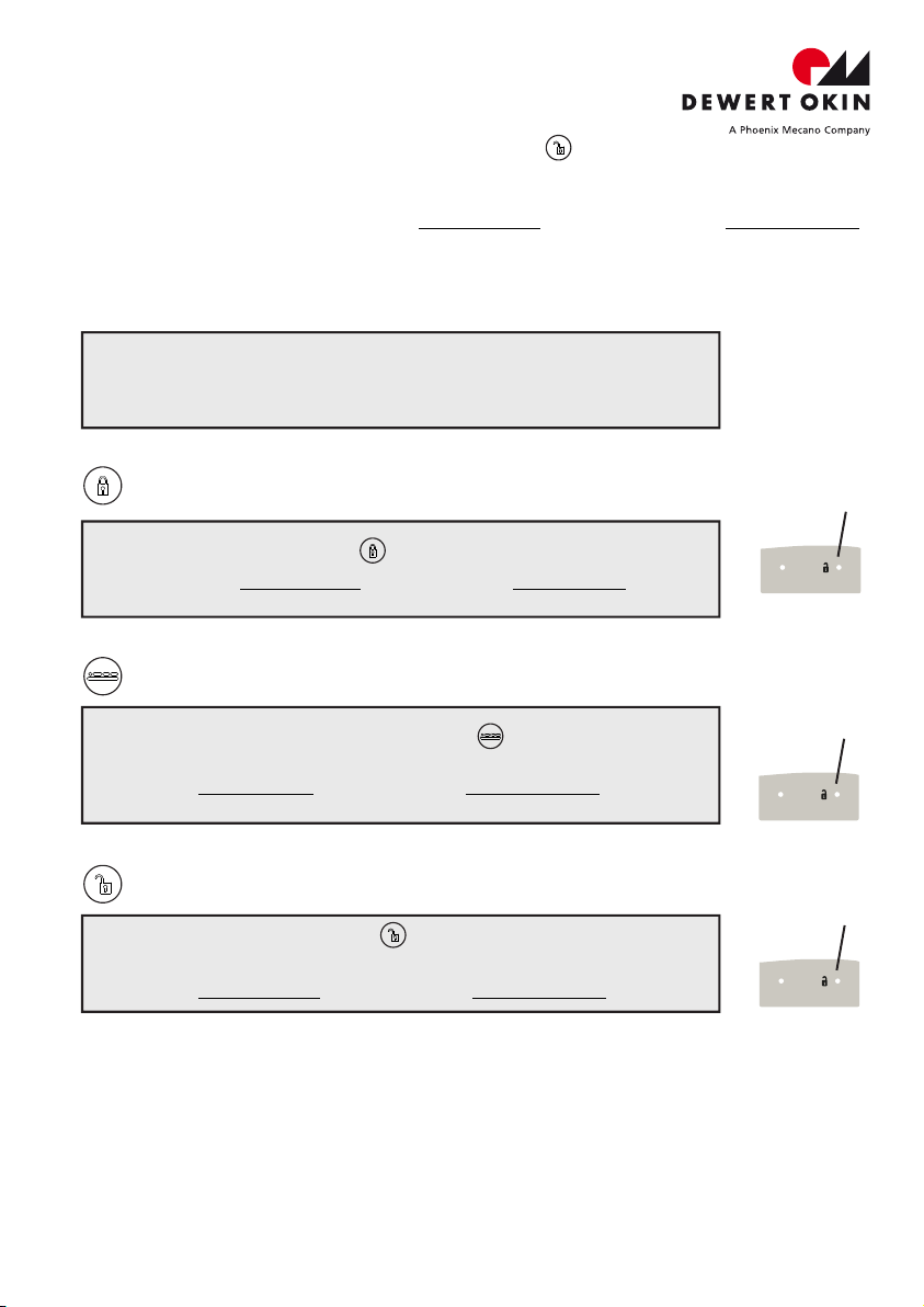
In order to guarantee single-fault protection you can lock the actuator movements via the
integrated locking device. In doing so, the motor circuits are disconnected by
electromechanic switch elements.
Ÿturn the locking switch to mode "locked",
Ÿcheck this by activating the adjustment key,
Ÿif locking is activated but movements will still be possible please exchange handset
for a new one.
Information on battery power
ŸIf you are operating your system on battery power then observe the following notice.
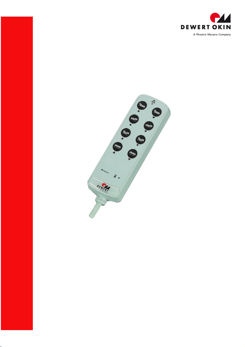
Designated Use
®
The Handset IPROXX is intended for connect with DEWERT drive control unit of Type
CARE (L), HOSP (L), i.e. MCL, SGAG, etc.
The Handset IPROXX®is not intended for use ...
Ÿin the proximity high-frequency surgical equipment and defibrillators,
Ÿin an environment where inflammable or explosive gases or vapours
(e.g. anaesthetics) are likely to occur,
Ÿin a damp environment, i.e. outdoors or
Ÿin beds intended for cleaning in wash tunnels.
Note: After it has been used to move your application (in the turnkey lock
positions or ), the Handset IPROXX handset should be
®
turned back to its locked position (turnkey lock position ). This
prevents the system from gradually discharging when the battery is
connected!
04/2020
ID 56171 3.0
04/2020
ID 56171 3.0
®
IPROXX SM/SM+/SMP