Phoenix Mecano HARTMANN ELECTRONIC PCIE101A User manual

www.hartmann-electronic.com Rev. 1.1 1
CPCI Rear Transmission
Remote Controller
PCIE101A / PCIE100A
User’s Manual

www.hartmann-electronic.com Rev. 1.1 2
Revision History
Version: Notification of Change Date
1.0
16.12.2019
1.1 Add PCIE101A PC Card; correct the wording 03.02.2020
1.2 Add PCIe 2m Kabel to ordering Information
Imprint:
Hartmann Electronic GmbH
Motorstraße 43, D-70499 Stuttgart (Weilimdorf)
Telephone: +49 711 1 39 89-0
Telefax: + 49 711 8 66 11 91
Internet: www.hartmann-electronic.com
HartmannElectronicisalongstandingpartnerofthe
Embeddedindustryandhasavarietyofdifferentbackplanes.
Withourwideselectionofbackplanesandenclosureyoucan
Buildyourperfectsystemplatform
Copyright©2017
All rights and technical modifications reserved

www.hartmann-electronic.com Rev. 1.1 3
Contents
1. Safety.....................................................................................................................................................................4
Intended Application..............................................................................................................................................4
Safety Symbols .....................................................................................................................................................4
General Safety Precautions ..................................................................................................................................4
Safety Instructions.................................................................................................................................................5
Protection Against Electromagnetic Interference (EMI).....................................................................................5
Electrostatic Discharge Precautions...................................................................................................................5
Installation ..........................................................................................................................................................5
Location..............................................................................................................................................................5
Voltage Hazards.................................................................................................................................................5
System Overheating...........................................................................................................................................5
Mounting Considerations....................................................................................................................................6
Electrical Hazards...............................................................................................................................................6
Board Installation................................................................................................................................................6
2. Product Description ...............................................................................................................................................7
Related Documentation.........................................................................................................................................7
Chassis Description...............................................................................................................................................8
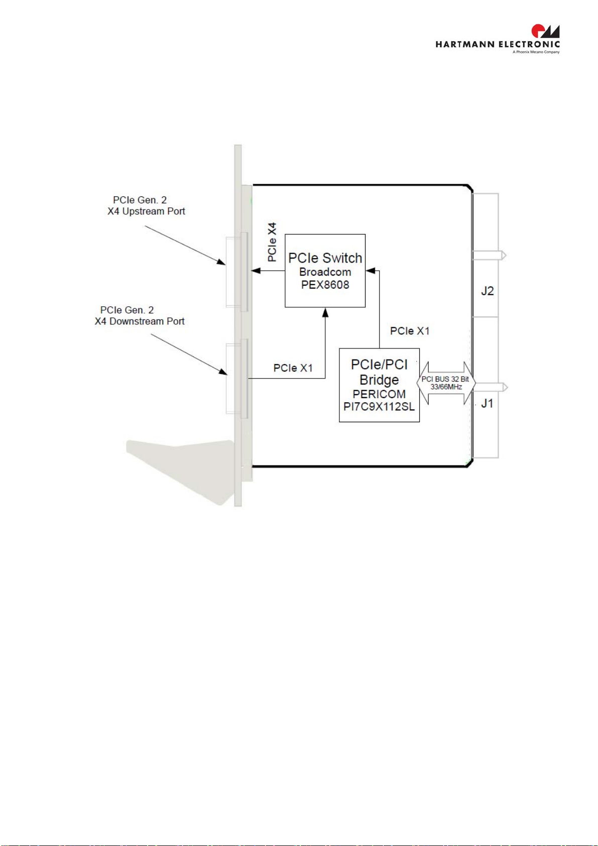
Block Diagram.......................................................................................................................................................9
PCIE101A PCIe Gen. 3 X4 PC Card..................................................................................................................9
PXE100A PCIe Gen. 2 Uplink to CPCI ............................................................................................................10
Front Panel LEDs................................................................................................................................................11
3. Installation............................................................................................................................................................12
Installing Hardware..............................................................................................................................................12
Installing a further CPCI Remote Controller at the PCIe X4 Downstream Port..................................................14
Installing Software...............................................................................................................................................15
4. Specification ........................................................................................................................................................16
Electrical..............................................................................................................................................................16
DC Input ...........................................................................................................................................................16
Operating Environment ....................................................................................................................................16
Electromagnetic Compatibility..........................................................................................................................17
5. Pin Assignment....................................................................................................................................................19
6. Ordering Information............................................................................................................................................20

www.hartmann-electronic.com Rev. 1.1 4
1. Safety
Intended Application
The PCI series remote controller kit is not designed for stand-alone use -- in order to enable stand-alone
functionality, additional elements are required. An operational system is achieved only by way of
appropriate CPCI Cards.
The completion and final testing of the units have been carried out by qualified technicians. These
instructions are intended to assist those who are qualified to operate this equipment.
Make sure that the finished system complies with the safety regulations currently applicable in the
country it is going to be used.
Safety Symbols
Hazardous voltage!
Familiarize yourself with the danger of electrical voltages and the safety
precautions before starting to work with parts that carry dangerous voltages
Caution!
This symbol indicates a condition where damage of the equipment or injury of
the service personnel could occur. To reduce the risk of damage or injury,
follow all steps or procedures as instructed.
Danger of electrostatic discharge!
Static electricity can damage sensitive components in a system. To avoid
damage, wear ESD wrist straps or at regular intervals touch blank enclosure
parts.
General Safety Precautions
Warning!
Voltages over 60 VDC can be present in this equipment. This equipment is
intended to be accessed, to be installed and maintained by qualified and trained
service personnel only.
This equipment is designed in accordance with protection class 1!
lt must therefore be operated only with protective GND/earth connection!

www.hartmann-electronic.com Rev. 1.1 5
Safety Instructions
This user's manual is intended for system Integrators and hardware/software engineers.
This product has been designed to meet the relevant standard industrial safety requirements. It is not
intended to be used in applications other than that of its specific area of the office telecommunication
industry and industrial control. It is not designed nor intended for use in safety-critical applications, life-
sustaining appliances or in aircraft.
Only trained personnel or persons qualified in electronics or electrical engineering are authorized to
install, operate or maintain the product.
This section provides safety information about the following:
Protection against electromagnetic interference (EMI)
Electrostatic discharge precautions
System installation
ProtectionAgainstElectromagneticInterference(EMI)
The product has been tested and found to comply with the limits for a Class A digital device, pursuant to
part 15 of the FCC Rules, EN 55022 Class A.
To ensure proper EMC shielding, operate the chassis only with all free slots populated with filler panels.
Ensure that all EMI gaskets make correct contact.
ElectrostaticDischargePrecautions
Electronic components can easily be destroyed by electrostatic discharge which can occur between
chassis components and a person.
Before working on the chassis make sure that you are working in an ESD-safe environment.
Installation
To avoid chassis damage verify that the system environment meets the environmental and power
requirements given in this guide before installation consider these guidelines:
Location
Locate the system in a stable area free of excessive movement or jarring, dust, smoke, and electrostatic
discharge (ESD). Make sure that the temperature does not exceed the operating temperature given in
the environmental requirements in this guide and allow room for proper air flow for cooling.
VoltageHazards
The system is powered with a power supply the mains voltage is 115/230VAC.
(Voltage range 90VAC to 264VAC)
This voltage is considered hazardous.
SystemOverheating
Ensure a clearance of at least 10 cm on both sides of the chassis to allow the needed air flow for proper
system cooling.
Shelf ambient temperature may not exceed 50°C.

www.hartmann-electronic.com Rev. 1.1 6
MountingConsiderations
Assure that all components, structural or otherwise, were not loosened nor damaged during shipment
prior to use.
Do not operate under loose or damaged conditions as it may damage other parts of the system at large.
ElectricalHazards
The caution label on the system's rear, near the grounding studs, indicates a needed earth connection
due to the potential for high-leakage current which is considered hazardous.
High leakage current can cause injuries.
Ensure that the system is properly grounded at all times. Please account for the following condition:
This equipment shall be connected directly to the AC supply system earthing
BoardInstallation
Electrostatic discharge and incorrect board installation or removal can damage circuits or shorten their
life.
Before touching the boards or electronic components, make sure that you are working in an ESD-
safe environment
Boards should be inserted and removed using their handles, do not force the board by applying pressure to
the front panel.

www.hartmann-electronic.com Rev. 1.1 7
2. Product Description
The PCIE100A CPCI Remote Controller is designed to operate in a CPCI System Slot. The controller complies
with the 19” Rear Transmission module form factor. With its use, a conventional Desktop PC is used ,to control a
CPCI Chassis.
With the use of a Hartmann Electronic PCIE101A PC adapter, the Remote Controller is connected with a
standard PCIe X4 cable to the desktop PC. The interface of the PXE100A, as well as the interface of the
PCIE101A, are fully compliant with the PCI Express External Cable Specification, Revision 2.0.
That Downstream Port can be linked to another Remote Controller’s upstream port.
Related Documentation
‐PCI Express® External Cabling Specification Revision 2.0
‐CompactPCI PICMG 2.0 R. 3.0
‐PCI Express® Card Electromechanical Specification Revision 2.0
‐PCI Local Bus Specification Revision 3.0

www.hartmann-electronic.com Rev. 1.1 8
Chassis Description
The CPCI Remote controller requires Rear I/O connectors on the CPCI Backplane’s System Slot. The Space-
saving 4 TE design allows ample space for additional system components as well as further CPCI Modules,
conveniently placed directly next to the controller.

www.hartmann-electronic.com Rev. 1.1 9
Block Diagram
PCIE101APCIeGen.3X4PCCard
Figure 2-2 illustrates the hardware implementation of the PCIE101A PC Card.
Figure 2-1 PCI Express X4 host card
The Block Diagram above outlines the Hardware implementation of the PCIe PC Card PCIE101A. As shown in
Figure 2-1, the PC-Card is available in both high and low profile versions of the front panel. This allows the PC
card to be plugged into any Desktop PC Chassis.
The PC Card can be plugged into a PCIe X4, PCIe X8 or PCIe X16 slot. The card re-drives a PCIe X4 link to the
standard PCIe X4 Cable Connector.
PCIe Gen. 3 data rates are supported with the card by utilizing a PCIe X4 Link.

www.hartmann-electronic.com Rev. 1.1 10
PXE100APCIeGen.2UplinktoCPCI
Figure 2-1 illustrates the hardware implementation of the CPCI Rear Transmission Remote Controller.
Figure 2-1 CPCI Remote Controller Block Diagram
The Block Diagram above outlines the Hardware implementation of the CPCI Remote Controller. The Controller’s
Downstream Port is mechanically implemented through a standard PCIe X4 Cable connector. A PCIe Gen. 2 X1
Link is supported, electrically, at the downstream side.
The PCIe/PCI Bridge supports both, 33Mhz and 66 MHz operation. The extended implementation of the
PERICOM, PI7C9X112SL PCIe/PCI Bridge allows arbitration support for up to 7 CPCI Modules. In order to
cascade a 2nd hierarchy chassis, the Downstream Port of the 1st hierarchy chassis is connected, through a PCIe
X4 cable, to the upstream Port of the 2nd hierarchy chassis.
The controller can be plugged into any CPCI chassis’ rear system controller slot, which is compliant with the
necessary specifications. These specifications are listed in the “related document” section.

www.hartmann-electronic.com Rev. 1.1 11
Front Panel LEDs
Figure 2-2 shows the location of the front panel LEDs.
Table 2-1 describes the front panel LED states
LED State Description
POW Green Chassis Power OK
Red One or more Power Rails of the chassis are not within the specified range
RES Green Function OK. PCI Express Reset is not asserted
Red PCI Express Interface is hold in Reset
RESP Green Function OK. PCI Reset is not asserted
Red PCI Interface is hold in Reset

www.hartmann-electronic.com Rev. 1.1 12
3. Installation
Installing Hardware
Installing the PCIE101A PC Card
Complete the following steps to install the PCIE100A in your computer.
1) Power off your computer.
Danger of electrostatic discharge!
To protect both yourself and the computer from electrical hazards,
your computer should remain off until you finish installing all hardware as
instructed.
2) Remove the top cover or access port to the PCI Express expansion slots.
3) Touch the metal part of the power supply case inside the computer to discharge any static electricity that might
be on your clothes or body.
4) Unplug the computer and wait 30 seconds to allow the energy stored in the computer’s power supply to fully
dissipate.
5) Select any available PCI Express expansion slot (X4, X8 or X16).
6) Locate the metal bracket that covers the cut-out in the back panel of the computer for the slot you have
selected. Remove and save the bracket-retaining screw and the bracket cover.
7) Line up the PCIE101A with the slot on the back panel. Slowly lower the PCIE101A until its card-edge
connector is resting on the expansion slot receptacle. Using slow, evenly distributed pressure, press the
PCIE101A straight down until it seats in the expansion slot.
8) Secure the PCIE101A to the back-panel rail using a bracket retaining screw.
9) Replace the computer cover.
10) Plug in the computer.

www.hartmann-electronic.com Rev. 1.1 13
Connecting a single CPCI System to the Desktop PC
1) Install the Controller into the appropriate system slot.
Danger of electrostatic discharge!
To protect both yourself and the computer from electrical hazards,
The CPCI system should remain off until you finish installing all hardware as
instructed.
2) Power down your host system and the external CPCI system.
3) Insert the CPCI board into the system slot of the CPCI system. Make sure that the front handle of the CPCI
board is locked.
4) Connect your host system through a PCIe X4 Cable to the upstream port of the CPCI board.
5) Before applying power to the external CPCI system, make sure that all other CPCI boards are installed
correctly. You may follow the instruction of your CPCI board supplier to install the board correctly.
6) Power up your external CPCI system.
7) Power up your host system.
8) The CPCI Remote controller should be enumerated automatically. There are no additional software drivers
required.
WARNING: Boards should slide easily when installing or removing them from the
shelf. Forcing the boards may cause damage to the interface connector pins.
Install filler panels in unused or empty slots.
Filler panels consists of a front panel (with or w/o air baffles), EMC gasket and mounting screws.
WARNING:
Close all empty chassis slots with filler panels. The filler panel prevents fan air from
escaping out of open slots.

www.hartmann-electronic.com Rev. 1.1 14
Installing a further CPCI Remote Controller at the PCIe X4 Downstream Port
1) Power down the host system and your first and second party CPCI system.
First party system: System that is connected directly to the host system.
Second party system: System that is connected to the host through the second party system.
2) Insert the CPCI Board into the system slot of the first party CPCI system.
Make sure that the front handle of the CPCI board is locked.
3) Connect your host system through a PCIe X4 Cable to the upstream port of the board, that is plugged into your
first party system.
4) Insert the CPCI Board into the system slot of your second party CPCI system.
Make sure that the front handle of the CPCI board is locked.
5) Connect the downstream port of the first party Remote Controller with the upstream port of the second party
Remote controller via a PCIe X4 Cable.
6) Power up your second party CPCI system
8) Power up your first party CPCI system
9) Power up your host system
10) Both of your CPCI systems should be enumerated automatically
Note: The system that is at the lowest level of the hierarchical PCIe structure should
be powered up first.
WARNING: Boards should slide easily when installing or removing them from the
shelf. Forcing the boards may cause damage to the interface connector pins.
1.) Install filler panels in unused or empty slots.
Filler panels consists of a front panel (with or w/o air baffles), EMC gasket and mounting screws.
WARNING:
Close all empty chassis slots with filler panels. The filler panel prevents fan air from
escaping out open slots.

www.hartmann-electronic.com Rev. 1.1 15
Installing Software
The Remote Controller does not require any additional software drivers. The Controller is enumerated fully with
the use of conventional standard PCI-to-PCI bridge drivers.

www.hartmann-electronic.com Rev. 1.1 16
4. Specification
Electrical
DCInput
Applied through CPCI Backplane
Operating Voltage Range
+3,3V and +VI/O. The +VI/O-Voltage can be either +3,3V or
+5V.
OperatingEnvironment
Operating temperature range: -10… +85 °C
Storage temperature range: -40 °C… + 125 °C

www.hartmann-electronic.com Rev. 1.1 17
ElectromagneticCompatibility

www.hartmann-electronic.com Rev. 1.1 18
Mechanical
Form Factor:
Eurocard (80x100mm): suitable for 19“-Racks. Front panel width 4HP (20.32mm).
Slot Requirement:
Single rear CPCI system controller slot

www.hartmann-electronic.com Rev. 1.1 19
5. Pin Assignment
The Pin assignment applies with the CompactPCI PICMG 2.0 R. 3.0 specification.
‐System Controller Slot
22 GND GA4 GA3 GA2 GA1 GA0 GND
21 GND CLK6 GND BP(I/O) BP(I/O) BP(I/O) GND
20 GND CLK5 GND BP(I/O) BP(I/O) BP(I/O) GND
19 GND BP(I/O) BP(I/O) BP(I/O) BP(I/O) BP(I/O) GND P2
18 GND BP(I/O) BP(I/O) BP(I/O) BP(I/O) BP(I/O) GND
/
17 GND BP(I/O) BP(I/O) BP(I/O) REQ6# GNT6#
GND J2
16 GND BP(I/O) BP(I/O) BP(I/O) BP(I/O) BP(I/O) GND
15 GND BP(I/O) BP(I/O) BP(I/O) REQ5# GNT5# GND
14 GND BP(I/O) BP(I/O) BP(I/O) BP(I/O) BP(I/O) GND
13 GND BP(I/O) BP(I/O) BP(I/O) BP(I/O) BP(I/O) GND
12 GND BP(I/O) BP(I/O) BP(I/O) BP(I/O) BP(I/O) GND
11 GND BP(I/O) BP(I/O) BP(I/O) BP(I/O) BP(I/O) GND
10 GND BP(I/O) BP(I/O) BP(I/O) BP(I/O) BP(I/O) GND C
9 GND BP(I/O) BP(I/O) BP(I/O) BP(I/O) BP(I/O) GND O
8 GND BP(I/O) BP(I/O) BP(I/O) BP(I/O) BP(I/O) GND N
7 GND BP(I/O) BP(I/O) BP(I/O) BP(I/O) BP(I/O) GND N
6 GND BP(I/O) BP(I/O) BP(I/O) BP(I/O) BP(I/O) GND E
5 GND BP(I/O) BP(I/O) BP(I/O) BP(I/O) BP(I/O) GND C
4 GND BP(I/O) BP(I/O) BP(I/O) BP(I/O) BP(I/O) GND T
3 GND CLK4 GND GNT3# REQ4# GNT4# GND O
2 GND CLK2 CLK3 SYSEN# GNT2# REQ3# GND R
1 GND CLK1 GND REQ1# GNT1# REQ2# GND
25 GND 5V REQ64# ENUM# 3.3V 5V GND
24 GND AD[1] 5V V(I/O) AD[0] ACK64# GND
23 GND 3.3V AD[4] AD[3] 5V AD[2] GND
22 GND AD[7] GND 3.3V AD[6] AD[5] GND P1
21 GND 3.3V AD[9] AD[8] M66EN C/BE[0]# GND
/
20 GND AD[12] GND V(I/O) AD[11] AD[10] GND J1
19 GND 3.3V AD[15] AD[14] GND AD[13] GND
18 GND SERR# GND 3.3V PAR C/BE[1]# GND
17 GND 3.3V IPMB SCL IPMB SDA GND PERR# GND
16 GND DEVSEL# GND V(I/O) STOP# LOCK# GND C
15 GND 3.3V FRAME# IRDY# GND TRDY# GND O
12-14 KEY AREA N
11 GND AD[18] AD[17] AD[16] GND C/BE[2]# GND N
10 GND AD[21] GND 3.3V AD[20] AD[19] GND E
9 GND C/BE[3]# GND AD[23] GND AD[22] GND C
8 GND AD[26] GND V(I/O) AD[25] AD[24] GND T
7 GND AD[30] AD[29] AD[28] GND AD[27] GND O
6 GND REQ0# GND 3.3V CLK0 AD[31] GND R
5 GND BRSVP1A5 BRSVP1B5 RST# GND GNT0# GND
4 GND IPMB PWR HEALTHY# V(I/O) INTP INTS GND
3 GND INTA# INTB# INTC# 5V INTD# GND
2 GND TCK 5V TMS TDO TDI GND
1 GND 5V -12V TRST# 12V 5V GND
Pin Z A B C D E F
length of pins (front view)
short medium long

www.hartmann-electronic.com Rev. 1.1 20
6. Ordering Information
Ordering Number Description PCI V(I/O)
1H00007120 CPCI Rear Board – PCIeX4 to 8CPCI-Slots +5 V / +3V3
1H00005304 PC Card PCie X4 to PCIe X4_Cable (Low Profile) -
1H00005305 PC Card PCie X4 to PCIe X4_Cable (High Profile) -
F006.02170 PCIe X4 Gen. 2 Cable (1m) -
F006.02180 PCIe X4 Gen. 2 Cable (3m) -
F006.02190 PCIe X4 Gen. 2 Cable (2m)
This manual suits for next models
1
Table of contents
Other Phoenix Mecano Remote Control manuals

Phoenix Mecano
Phoenix Mecano DewertOkin IPROXX SM User guide

Phoenix Mecano
Phoenix Mecano OKIN REFINED RF28 User manual

Phoenix Mecano
Phoenix Mecano DewertOkin IPROXX SE User guide

Phoenix Mecano
Phoenix Mecano OKIN Refined RF3017A User manual

Phoenix Mecano
Phoenix Mecano Dewert Okin CU165 User manual

Phoenix Mecano
Phoenix Mecano OKIN Refined RF3409 User manual

Phoenix Mecano
Phoenix Mecano Dewert Okin RF-TOUCH User manual

Phoenix Mecano
Phoenix Mecano Okin Refined JLDK3706 User manual

Phoenix Mecano
Phoenix Mecano OKIN RF ECO BT M User manual