Phoenix 2700-DHP User manual

Phoenix 2700 DHP
July 2018
1
OPERATING MANUAL
Please read this manual carefully before operating!

Phoenix 2700 DHP
July 2018
2
Table of Contents
Contents
Page
1. Introduction……………………………………………………………..
3
2. Important Safety Instructions…………………………………………...
3
3. Installation Safeguards…….……………………………………............
3
4. General Safeguards……………………………………………………..
5
5. Operating Conditions…………………………………………………...
6
6. Operating Precautions…………………………………………………...
6
7. Installation……………………………………………………................
7
8. System Components………………………………………….................
8
9. Control Panel (Front) …………………………………………………..
10. Power Panel (Rear) …………………………………………………...
11. Safety Shield …………………………………………………………...
12. Feed Table ……………………………………………………………...
13. Roller Gap Adjustment …………………………………………………
14. Temperature Display…………………………………………………….
15. Operation………………………………………………………………..
16. Roller Cleaning Function ……………………………………………….
17. Auto Sleep Function ……………………………………………………
18. Motor Switch Safety Function ………………………………………….
19. Heat Sensor Safety Function ……………………………………………
20. Loading Film Rolls ………………………………………………………
21. Using 2 ¼” Film core adaptors ………………………………………….
22. Threading Film ……………………………………………………………
23. Adjusting Brake Tension ………………………………………………….
24. Troubleshooting ………………………………………………………….
25. Specifications …………………………………………………………….
26. Warranty ………………………………………………………………….
9
9
10
11
12
12
13
15
15
15
16
16
19
21
22
23
24
25
Phoenix 2700 DHP
July 2018
3
1. Introduction
Thank you for choosing the Phoenix 2700 DHP laminator. It has been designed and manufactured to
provide years of continuous service. Please read this manual thoroughly before operating. Please
inspect the box and the laminator for shipping damage. Damage should be brought to the attention of
the delivering carrier immediately.
We reserve the right to make changes to this publication and to the products described in it without
notice. The details given in this manual are based on the most recent information available to us. They
may be subject to change in the future. We retain the right to make changes to the construction or the
design of our products without accepting any responsibility for modifying earlier versions.
WARNING! Any unauthorized changes or modifications to this unit without our prior written approval
will void the user’s warranty and will transfer health and safety obligations to the end user.
CAUTION! Please pay attention to all passages with these symbols. This information is
vital to preventing user injury and/or damage to the unit. Failure to follow this information could void
the user’s warranties and transfer all safety obligations to the user.
2. Important Safety Instructions
In this operating manual, you will find important safety messages regarding the product.
Read these instructions carefully, failure to comply with the following safety procedures could
result in serious injury.
WARNING Do not attempt to service or repair the laminator. Only authorized maintenance
and service technicians should make repairs.
WARNING Do not connect the laminator to an electrical supply or attempt to operate the
laminator until you have completely read these instructions. Maintain these
instructions in a convenient location for future reference.
WARNING To guard against injury, the following safety precautions must be observed in the
installation and use of the laminator.
WARNING Ensure the safety shield is in place before operating the Laminator.
Operating without the safety shield can cause serious injury.
3. Installation Safeguards
•Shipping damage should be brought to the immediate attention of the delivering carrier.
•Avoid locating the laminator near sources of heat or cold. Avoid locating the laminator in
the direct path of forced, heated or cooled air.
•The receptacle must be located near the equipment and easily accessible.
•Connect the power cord provided with the laminator to a suitably grounded outlet
only. This machine must have reliable earth ground wire to ensure the safety of the
machine during operations.
Phoenix 2700 DHP
July 2018
4
•Contact an electrician should the power cord provided with the laminator not match the
receptacles at your location.
•Ensure that the voltages of the power supply you are using match the rated working
voltages before operations. Do not use incorrect power supply.
•Do not use damaged wires or sockets. If abnormal conditions occur, switch off the
power supply first.
•Only a licensed electrician should install wiring and outlet for the laminator.
•Do not defeat, disable, or remove electrical and mechanical safety equipment such as
interlocks, shields and guards.
NOTE: This equipment has been tested and found to comply with the limits for a Class B
digital device, pursuant to part 15 of the FCC Rules. These limits are designed to provide
reasonable protection against harmful interference in a residential installation. This equipment
generates, uses and can radiate radio frequency energy and, if not installed and used in
accordance with the instructions, may cause harmful interference to radio communications.
However, there is no guarantee that interference will not occur in a particular installation. If
this equipment does cause harmful interference to radio or television reception, which can be
determined by turning the equipment off and on, the user is encouraged to try to correct the
interference by one or more of the following measures:
—Reorient or relocate the receiving antenna.
—Increase the separation between the equipment and receiver.
—Connect the equipment into an outlet on a circuit different from that to which the receiver is
connected.
—Consult the dealer or an experienced radio/TV technician for help.
Changes or modifications not expressly approved by the party responsible for compliance
could void the user's cTUVus safety certification.

Phoenix 2700 DHP
July 2018
5
4. General Safeguards
•Keep hands, long hair, loose clothing, and articles such as neckties away from rollers to
avoid entanglement and entrapment. The rollers have pinch points that can trap body parts
or clothing and cause serious injury.
•Do not use the machine for purposes other than lamination, otherwise damages to the
machine or accidents may occur.
•Keep out of reach of children.
•Keep flammable and wet objects away from the machine.
•Do not use flammable sprays or materials when cleaning the machine.
•Do not leave the machine unattended during operations.
•Do not put burrs, sharp blade or rigid materials in between the two rubber rollers.
•Do not attempt to laminate items that exceed total recommended material thickness of the
unit.
•Do not place foreign object inside the machine.
•Do not cut adhesive films directly on the surface of the rollers to avoid damaging the rubber
coating.
•Shut down the machine after laminating to avoid misusing this machine by others.
•Turn off the power switch and unplug the power cord before moving the machine.
•Note the locations of foot wheels while moving or operating this machine to avoid injuries
to your feet.
•Disconnect from the power supply before repair or maintenance.
•Disconnect from the power supply when the machine is not in use for a long time.
•When the machine lies idle for a long period of time, raise the top rubber roller to avoid the
damage to the rubber surface.
•Perform only the routine maintenance procedures referred to in these instructions.

Phoenix 2700 DHP
July 2018
6
5. Operating Conditions
•Environment requirements:
Ambient temperature: 50⁰F - 104⁰ F
Humidity: 30%—80%; Ideal humidity: 55%
•Due to the static on film rolls, you should try to keep the environment clean.
•Provide enough space around machine to ensure the safe and effective operation. The
minimum area covered is 8 ft. x 10 ft.
•Do not directly cut the films on the surfaces of the rubber rollers to avoid damages to the
rollers.
•Do not put burrs, sharp knives or extra thick and hard materials in between the rollers. Do
not leave objects like tools, rulers, knives, etc on the working panels or the side cabinets to
avoid there being rolled into the machine accidentally and damaging the rollers.
•For repairs and replacements, please contact your local distributor. Unauthorized repairs
and dismantling will affect future maintenances of the machines.
Warning: Do not keep the machine in direct sunshine or near it.
Do not keep the machine in dusty areas or places with strong vibrations.
6. Operating Precautions
•The following objects should not be subject to lamination:
oVolatile substances or any thermal-sensitive substances (e.g. Vinyl chloride).
oValuable, unique and unrecoverable objects.
oObjects subject to change of color and nature attributable to heat (e.g. thermal sensitive
paper, crayons etc.).
•Improper operation may lead to lamination failure, therefore, when using this laminator, one
must choose the correct relations between the machine speed, laminating film thickness, and the
material to be laminated.
•The guiding principles of lamination are:
oThe thicker the laminating film and material to be laminated, the slower the machine
speed
oConversely, the thinner the laminating film and material to be laminated, the higher the
speed.
•For best results, try similar material to find the suitable temperature and speed relationship
before performing lamination on final product.
•Never leave the operating machine unattended.
Caution: Safety Shield and Feed Tray must be in their proper position for operation.
Phoenix 2700 DHP
July 2018
7
7. Installation
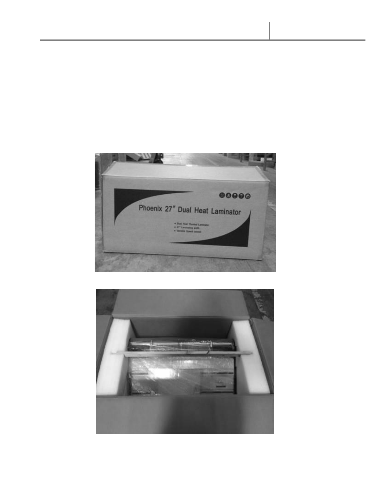
1. Lift machine straight up and out of the box.
2. Set machine on sturdy table or optional machine stand.
3. Remove plastic cover and operating manual.
4. Remove the feed tray and safety shield.
NOTE: Remove all parts from shipping crate and boxes. Inspect parts and
the machine carefully. Any missing parts should be reported to the
shipper upon receipt of shipment.
Phoenix 2700 DHP
July 2018
8
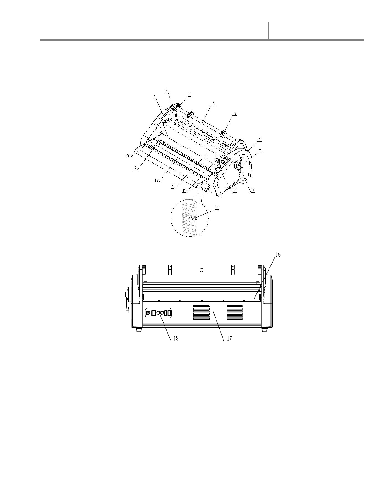
8. System Components
1. Left Side Cabinet 10. Feed Table safety latch
2. Tension Adjustment 11. Safety Shield safety latch
3. Supply Roll Bracket 12. Safety Shield
4. Supply Shaft 13. Feed Table
5. 2 ¼” Core adaptor 14. Side Guide
6. Right Side Cabinet 15. Top Roller
7. Roller Gap Adjustment 16. Bottom Roller
8. Roller Gap Handle 17. Back Panel
9. Control Panel 18. Rear Power Panel

Phoenix 2700 DHP
July 2018
9
9. Control Panel (Front)
10. Power Panel (Rear)
1. Power Indicator
2. Ready Light
3. Temperature Adjustment
4. Speed Adjustment
5. Forward/Reverse Switch
2
1
3
4
5
1. Power Cord
2. Main On/Off switch
3. Heater Fuse
4. Motor Fuse
5. Fan Switch
6. Heat Roller Switch
Phoenix 2700 DHP
July 2018
10
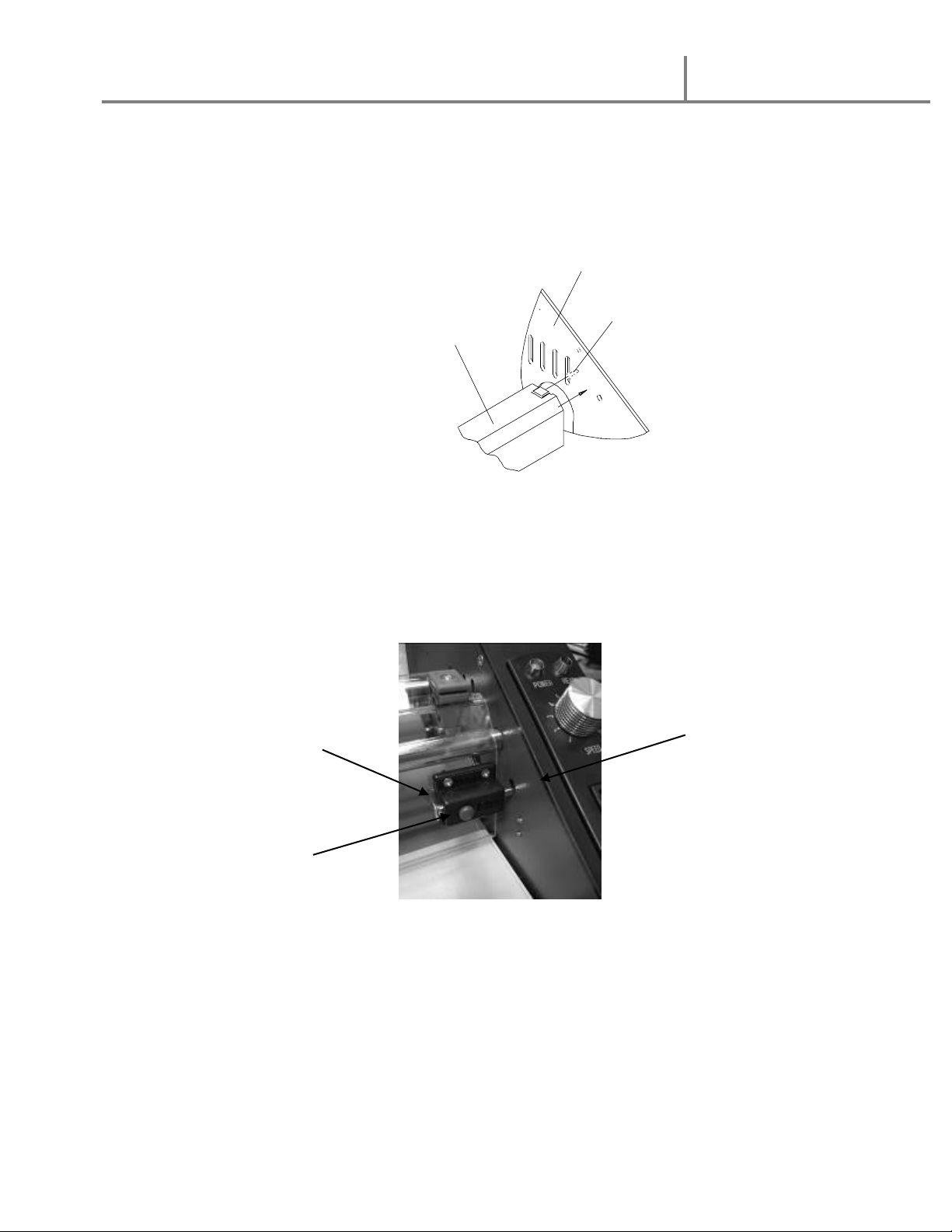
11. Safety Shield
1. Insert left side of shield with spring pin into positioning holes on left side frame.
2. Insert right side pin into positioning hole on right side frame.
3. Lower safety shield onto side support pins.
4. Slide Safety Shield latch to the right and locked position to engage the
safety interlock switch
5. To release the latch, press the Red button on the lock
Warning: Ensure the safety shield is in place before operating the Laminator.
Operating without the safety shield can cause serious injury.
Note: The laminator will operate only when the Safety Shield and Feed Table are
in the fully locked position. Both the interlocking switches must be activated
for power to be supplied to the motor
Side Frame
Support Pin
Front Safety Shield
Safety Latch
Release Button
Interlock switch
Table of contents
Other Phoenix Laminator manuals


