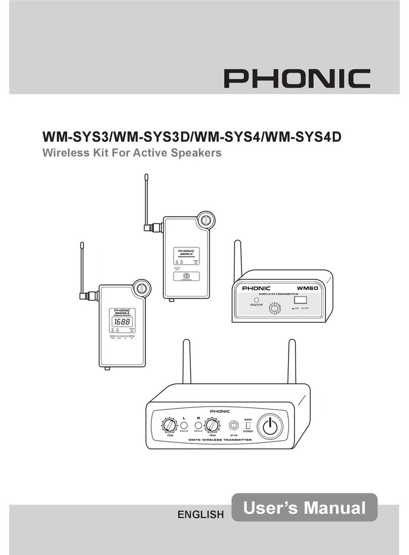
Phonic UM 30 User manual

UM 30/31/40/41/50/51 1
User’s Manual
Manual del Usuario
UM30/31/40/41/50/51
Wireless Microphone System
Micrófono Inalámbrico
English / Español /

INTRODUCTION...................4
FEATURES.............................4
SYSTEM COMPONENTS......4
OPERATION............................5
UM30/UM31..........................6
UM40/UM41/UM50/UM51.......8
BATTERYINSERTION...........10
INSTALLING THE RECEIVER
MODULE..............................11
SPECIFICATIONS...............12
CONTENTS
INTRODUCCION........................15
CARACTERISTICAS..................15
COMPONENTES DEL SISTEMA..15
OPERACION...............................16
UM30/UM31................................17
UM40/UM41/UM50/UM51...........19
INSERCIÓN DE BATERÍA..........21
INSTALANDO EL MODULO
RECEPTOR................................22
ESPECIFICACIONES.................23
CONTENIDO
..............................26
特色............................26
.....................26
..............................27
UM30/UM31.................28
UM40/UM41/UM50/UM51..30
........................32
................33
..............................34
Phonic preserves the right to improve or alter any information within this document without prior notice
Phonic se reserva el derecho de mejorar o alterar cualquier información provista dentro de este documento sin previo aviso
PHONIC
V1.0 03/25/2009
UM30/31/40/41/50/51
Wireless Microphone System
Micrófono Inalámbrico

UM 30/31/40/41/50/51 3
5HDG WKHVH LQVWUXFWLRQV EHIRUH RSHUDWLQJ WKLV
DSSDUDWXV
.HHSWKHVHLQVWUXFWLRQVIRUIXWXUHUHIHUHQFH
+HHGDOOZDUQLQJVWRHQVXUHVDIHRSHUDWLRQ
)ROORZDOOLQVWUXFWLRQVSURYLGHGLQWKLVGRFXPHQW
'RQRWXVHWKLVDSSDUDWXVQHDUZDWHURULQORFDWLRQV
ZKHUHFRQGHQVDWLRQPD\RFFXU
&OHDQRQO\ZLWKGU\FORWK'RQRWXVHDHURVRORUOLTXLG
FOHDQHUV8QSOXJWKLVDSSDUDWXVEHIRUHFOHDQLQJ
'RQRWEORFNDQ\RIWKHYHQWLODWLRQRSHQLQJV,QVWDOO
LQDFFRUGDQFHZLWKWKHPDQXIDFWXUHU

VLQVWUXFWLRQV
'R QRW LQVWDOO QHDU DQ\ KHDW VRXUFHV VXFKDV UDGLDWRUV
KHDWUHJLVWHUVVWRYHVRURWKHUDSSDUDWXVLQFOXGLQJ
'RQRWGHIHDWWKHVDIHW\SXUSRVHRIWKHSRODUL]HGRU
JURXQGLQJW\SHSOXJ$SRODUL]HGSOXJKDVWZREODGHV
ZLWKRQHZLGHUWKDQWKHRWKHU$JURXQGLQJW\SHSOXJ
KDVWZREODGHVDQGDWKLUGJURXQGLQJSURQJ7KHZLGH
EODGHRUWKHWKLUGSURQJLVSURYLGHGIRU\RXUVDIHW\,I
WKHSURYLGHGSOXJGRHVQRW LQWR\RXURXWOHWFRQVXOW
DQHOHFWULFLDQIRUUHSODFHPHQWRIWKHREVROHWHRXWOHW
3URWHFW WKH SRZHU FRUG IURP EHLQJ ZDONHG RQ RU
SLQFKHGSDUWLFXODUO\DWSOXJFRQYHQLHQFHUHFHSWDFOHV
DQGWKHSRLQWZKHUHWKH\H[LWIURPWKHDSSDUDWXV
2QO\ XVH DWWDFKPHQWVDFFHVVRULHV E\ WKH
PDQXIDFWXUHU
8VH RQO\ ZLWK D FDUW VWDQG WULSRG EUDFNHW RU
WDEOH E\ WKH PDQXIDFWXUHU RU VROG ZLWK
WKH DSSDUDWXV :KHQ D FDUW LV XVHG XVH FDXWLRQ
ZKHQ PRYLQJ WKH FDUWDSSDUDWXV
FRPELQDWLRQWRDYRLG LQMXU\IURPWLS
RYHU
8QSOXJWKLVDSSDUDWXVGXULQJOLJKWLQJ
VWRUPV RU ZKHQ XQXVHG IRU ORQJ
SHULRGVRIWLPH
5HIHU DOO VHUYLFLQJ WR VHUYLFH SHUVRQQHO
6HUYLFLQJLVUHTXLUHGZKHQWKHDSSDUDWXVKDVEHHQ
GDPDJHGLQDQ\ZD\VXFKDVSRZHUVXSSO\FRUGRU
SOXJLVGDPDJHGOLTXLGKDV EHHQVSLOOHGRU REMHFWV
KDYH IDOOHQ LQWR WKH DSSDUDWXV WKH DSSDUDWXV KDV
EHHQH[SRVHGWRUDLQRUPRLVWXUHGRHVQRWRSHUDWH
QRUPDOO\RUKDVEHHQGURSSHG
,03257$176$)(7<,16758&7,216
&$87,21725('8&(7+(5,6.2)(/(&75,&6+2&.
'21275(029(&29(525%$&.
1286(56(59,&($%/(3$576,16,'(
5()(56(59,&,1*7248$/,),('3(56211(/
7KH OLJKWQLQJ IODVK ZLWK DUURZKHDG V\PERO ZLWKLQ DQ
HTXLODWHUDO WULDQJOH LV LQWHQGHG WR DOHUW WKH XVHU WR WKH
SUHVHQFH RI XQLQVXODWHG
³
GDQJHURXV YROWDJH
´
ZLWKLQ WKH
SURGXFW

PDJQLWXGHWRFRQVWLWXWHDULVNRIHOHFWULFVKRFNWRSHUVRQV
7KH H[FODPDWLRQ SRLQW ZLWKLQ DQ HTXLODWHUDO WULDQJOH LV LQ
WHQGHGWRDOHUWWKHXVHUWRWKHSUHVHQFHRILPSRUWDQWRSHUDW
LQJDQGPDLQWHQDQFHVHUYLFLQJLQVWUXFWLRQVLQWKHOLWHUDWXUH
DFFRPSDQ\LQJWKHDSSOLDQFH
:$51,1* 7RUHGXFHWKHULVNRI RUHOHFWULFVKRFNGR
QRWH[SRVHWKLVDSSDUDWXVWRUDLQRUPRLVWXUH
&$87,21 8VH RI FRQWUROVRU DGMXVWPHQWVRU SHUIRUPDQFH
RI SURFHGXUHV RWKHU WKDQ WKRVH PD\ UHVXOW LQ
KD]DUGRXVUDGLDWLRQH[SRVXUH
7KH DSSDUDWXV VKDOO QRWEH H[SRVHGWR GULSSLQJRU VSODVKLQJ DQG WKDWQR REMHFWV ZLWK OLTXLGV VXFKDV YDVHV
VKDOOEH SODFHGRQ WKH DSSDUDWXV 7KH 0$,16 SOXJLV XVHGDV WKH GLVFRQQHFW GHYLFH WKH GLVFRQQHFW GHYLFH VKDOO
UHPDLQUHDGLO\RSHUDEOH
:DUQLQJ WKH XVHU VKDOO QRW SODFH WKLV DSSDUDWXVLQ WKH DUHD GXULQJ WKH RSHUDWLRQVR WKDW WKH PDLQV VZLWFK
FDQEHHDVLO\DFFHVVLEOH
&$87,21
5,6.2)(/(&75,&6+2&.
'212723(1

UM 30/31/40/41/50/514
Introduction
Congratulations on your purchase of one of the
many UM Wireless Microphone Systems. The
UMSystems,inconjunctionwithanyofPhonic’s
ne Wirelessly-enabled products, give people
a hassle free solution to having to run pesky
cables back and forth or having microphone
wires get in the way during performances. This
manual was designed to make the use of the
UM systems very simplistic, and it is advised
that user’s store this manual in an easy to nd
place in case it is needed for future reference.
Features
● Space-saving integrated compact receiving
module can be installed in Sound Ambas-
sador mobile sound system, Performer
speaker and Powerpod 865/885 plus pow-
ered mixers.
● Frequency Range:
614.175 ~ 804.800 MHz (FCC)
614.175 ~ 864.800 MHz (CE)
● 16 selectable UHF channels preset
● Oscillation mode: Microprocessor controlled
PLL synthesized
● Receiving Mode: Diversity
● Internal squelch and mute circuit mode that
can resist unusual noise
● SAW lters for rejection of non-RF content
System Components
For the Sound Ambassador��
UM30 Handheld System
● Handheld transmitter (HT-100)
● Wireless receiver module (UM-R10)
UM40 Lavaliere System
● Lavaliere microphone (ML-10)
● Bodypack transmitter (BT-200)
● Wireless receiver module (UM-R10)
UM50 Headset System
● Headset microphone (MH-20)
● Bodypack transmitter (BT-200)
● Wireless receiver module (UM-R10)
For the RoadGear, Performer and Powerpod
Plus Series��
UM31 Handheld System
● Handheld transmitter (HT-100)
● Wireless receiver module with metal case
(UM-R11)
UM41 Lavaliere System
● Lavaliere microphone (ML-10)
● Bodypack transmitter (BT-200)
● Wireless receiver module with metal case
(UM-R11)
UM51 Headset System
● Headset microphone (MH-20)
● Bodypack transmitter (BT-200)
● Wireless receiver module with metal case
(UM-R11)

UM 30/31/40/41/50/51 5
Operation
If using the Lavaliere or Headset Microphones
The ML-10 Lavaliere microphone includes a
clip that holds the lavaliere and can be attachedattached
to clothing, a tie or in a range of other places
where necessary. Plug the lavaliere mini XLR
female connector into the mini XLR male jack
of the bodypack.
The MH-20 Headset microphone should have
the microphone sitting near of your face, with
the rear hooks placed over your ears. The
microphone is adjustable so you can place it
closer to your mouth. Plug the headset mini
XLR female connector into the mini XLR male
jack of the bodypack.
Set up instructions
1. Lower the audio level before turning your
bodypack or handheld on.
2. Select the channel frequency on the hand-
held or bodypack so you can start transmit-
ting to the receiver.
3. Make sure that you have selected the same
channel number on the receiver (as the
handheld mic or bodypack). If not, your de-
vice will not receive the audio.
4. You can use the carry pouch along with your
bodypack for a more comfort and conve-
nience. Make sure that the antenna from the
bodypackisnot obstructedbyany objectsthat
could be in the path of the transmitter.
5. Check that the receiver’s RF, AF and power
LED’s are illuminated. If one or more of
these LEDs does not turn on, check your
conguration and try again.
6. Congure your mixer’s audio levels and you
are ready to go.
NOTE:
● Always make connections before connecting
any voltage to the equipment.
● If you’re using the bodypack transmitter, al-
ways connect the antenna before turning
it on. Not doing so may cause irreversible
damage to your transmitter.
ML-10
MH-20

UM 30/31/40/41/50/516
Inside Outside
UM30 / UM3130 / UM31
UHF Hand-Held System
1. Handheld Transmitter (HT-100�HT-100��
The very light Cardioid Wireless Microphone
includes a battery tray, on/off switch, LED
indicator and channel frequency selector. The
transmission antenna is built-in so that users
don’thaveto dealwith complicatedinstallations
or congurations.
I. Grille
This grill contains the magnetic transducer
(better known as pickup) and protects it from
damage. It also works as a wind screen and
pop stopper (on a lower level).
II. Battery Tray
This compartment holds two 1.5V AA batteries
that power the transmitter. Please take extreme
care when replacing batteries. Make sure that
the battery terminals polarities are correctly
positioned in the tray.
III. Channel Selector
Users can select from 16 different frequency
channels with this selector. This comes handy
if users nd problems with the frequency
allocations. If you nd noise problems on
your audio, or if your audio is too low or is
interrupted with for apparent reason, change
the frequency for a different one. If this doesn’t
x the problem, try to get closer to the receiver,
check the battery voltage level is correct, and
check that no objects are in the path between
the transmitter and receiver.
IV. Power On/Off switch
Located on the bottom of the microphone,
hold this button down for 2 seconds to turn the
microphoneonandoff. ThepowerLED willlight
up green if the power is on. If the handheld mic
doesn’t turn on (or the power LED illuminates
red), the batteries may need to be replaced.
V. ON LED Indicator
This bi-colored LED indicator lights up green
when the microphone is on. If the LED doesn’t
light up at all (or illuminates red) the batteries
may need to be replaced.

UM 30/31/40/41/50/51 7
2. Receiver Module (UM-R10 and UM-R11�UM-R10 and UM-R11��
This receives the RF signal sent from the
handheld transmitter. The UM-R10 has four
LED indicators: two RF, one AF and a Power
indicator. The UM-R11 simply has 1 for Power.
I. Power indicatorPower indicator
This LED will illuminate when the receiver
module receives power.
II. RF LED Indicators
When one of these LEDs is illuminates, it
indicates that the bodypack’s signal is being
received successfully. The RF LED that lights
up is determined by whichever antenna is
receiving a clearer signal from the transmitter.
If for some reason this LED does not turn on,
check your batteries in the transmitter and
conguration and try again.
III. AF LED Indicator
When this LED is illuminated, it indicates
that there is an audio signal present. If this
LED is not activated, check the head of the
microphone is correctly attached, and double
check your set up.
IV. Channel SelectorChannel Selector
This indicates the channel number that is
actually in use by the receiver. This number
should be identical to the channel selected on
the transmitter.
V. VolumeVolume
This dial determines the audio level of the
signal received by the UM-R10 receiver.
UM-R11
UM-R10

UM 30/31/40/41/50/518
UM40 / UM41 / UM50 / UM5140 / UM41 / UM50 / UM51
Lavaliere and Headset Systems
1. Bodypack Transmitter (BT-200�odypack Transmitter (BT-200�ack Transmitter (BT-200�BT-200��
This single unit modulates and transmits the
Audio Frequency to the receiver. It features a
transmission antenna and gain knob control.
You can connect a Lavaliere microphone, a
Headset microphone or any other microphone
that meets the bodypack specications.
I. Microphone Input
This input allows the connection of a condenser
microphone, either the MH-20 or the ML-10.
II. Power On/Off switch
The switch turns the bodypack on and off.
When pressed down for two seconds. Make
sure you lower your audio levels before turning
on. Not doing so could cause damage to your
speakers.
III. Antenna
Under no circumstances should the antenna be
removedor twisted. For maximum performance
and distance coverage, make sure that the
antenna’s line of sight to the transmitter is not
obstructed at all.
IV. LED Indicator
When the power switch is in the ON position,
this LED will be illuminated in green. If this LED
doesn’t turn on or light up in red, your batteries
will need to be replaced. When ligh up in red
means battery low.
V. Battery Tray
The battery tray is used to house the two 1.5V
AA batteries. Make sure that the position of the
batteries matches the polarity indicated on the
holder. Be sure to turn the power off before
changing batteries.
VI. Mic Gain adjust knob
This knob controls the sensitivity of the
microphone. Turn it clockwise to increase the
sensitivity, and counter-clockwise to decrease
it. Ensure that you do not set the level too high,
as this could cause easy overload.
VII. Channel SelectorChannel Selectorannel Selectornnel Selector
This indicates the channel number that is
actually in use by the transmitter. This number
should be identical to the channel selected on
the receiver.
VIII. Carry Pouch
This is a very handy bag that protects the
bodypack transmitter, and attaches to your belt.
This will no doubt be useful for conferences
and other events.

UM 30/31/40/41/50/51 9
2. Receiver Module (UM-R10 and UM-R11�
This receives the RF signal sent from the
bodypack transmitter. The UM-R10 has four
LED indicators: two RF, one AF and a Power
indicator. The UM-R11 simply has 1 for Power.
I. Power indicator
This LED will illuminate when the receiver
module receives power.
II. RF LED Indicators
When one of these LEDs is illuminates, it
indicates that the bodypack’s signal is being
received successfully. The RF LED that lights
up is determined by whichever antenna is
receiving a clearer signal from the transmitter.
If for some reason this LED does not turn on,
check your batteries in the transmitter and
conguration and try again.
III. AF LED IndicatorAF LED IndicatorF LED Indicator
When this LED is illuminated, it indicates
that there is an audio signal present. If this
LED is not activated, check the head of the
microphone is correctly attached, and double
check your set up.
IV. Channel SelectorChannel Selector
This indicates the channel number that is
actually in use by the receiver. This number
should be identical to the channel selected on
the transmitter.
V. Volume ControlVolume ControlControlControl
This dial determines the audio level of the
signal received by the UM-R10 receiver.
3.Condenser Lavaliere Microphone (ML-10�
Lavalieremicrophonesarewidelyusedinbroad-
casting and also for personal presentations.
Its small size make them perfect for any pro-
fessional application, also you will save space
and efforts. This is a condenser microphone, it
means that needs voltage to proper function,
this will be feed from the bodypack batteries,
and this also gives you a great signal gain.
4.Condenser Headset Microphone (MH-20�
The headset microphone is a very comfortably
tting microphone that sits perfectly on your
head. Brings you freedom of movement, this
way you can do all your activities while you are
speaking at the mic.
UM-R11
UM-R10

UM 30/31/40/41/50/5110
Battery Insertion
Handheld Microphone
1. Very carefully turn the base of the handheld
microphone counter-clockwise to unfasten
the battery tray.
2. Gently pull the inner part of the microphone
(which encompasses the battery tray) out.
3. Insert two brand new 1.5V AA batteries,
ensuring the polarity of the batteries corre-
sponds to the polarity indicated on the bat-
tery tray. Make sure the batteries are rmly
in place.
4. Reinsert the inner-part of the microphone
and turn the base clockwise to refasten.
Ensure the handheld mic is rmly together.
Bodypack Transmitter
1. On the back of the bodypack you will nd the
battery cover. Gently remove it by sliding itby sliding it
down..
2. Insert two brand new 1.5V AA batteries into
the battery compartment, making sure that
the polarity of the batteries is the same as
indicated. Ensure that they are rmly in
place.
3. Replace the cover.
Notes:s::
● Do not leave batteries in your microphone
or bodypack if they will not be used for long
periods of time.
● Do not mix new and old batteries.Do not mix new and old batteries.
● Do not mix alkaline with carbon batteries.
● Do not try to connect a DC converter or any
other voltage supply other than the ones that
are specied within this manual.

UM 30/31/40/41/50/51 11
Installing the Receiver Module
For UM 30/40/50
Sound Ambassador 75/120 Deluxe
Remove the 2 screws at the top of the protec-
tive cover, and remove the grounding PCB
from the compartment. Place the UM-R10 re-
ceiver into the slot revealed after removing the
cover, and screw the front panel of the receiver
in place.
For UM 31/41/51
Active Performer Speakers
Remove the compartment cover on the left
side of Performer speaker (left when facing
the rear). Remove the grounding PCB from
the golden nger socket. Insert the UM-R11 re-
ceiver into the module compartment, and use a
screw to secure it into place. Replace the com-
partment cover.
Powerpod 865 and 885 Plus
Open the wireless module compartment by
removing the single screw. Slide the UM-R11
module along the wall of the compartment door
and into the port connected to the door. Close
the compartment door and replace the screw.
RoadGear 120, 160 and 260
Opening the storage compartment on the rear
of the RoadGear's mixer, users will notice 2
module slots available. Insert the UM-R11 re-
ceiver module into one of these, use a screw to
secure it into place and close the compartment
again.

UM 30/31/40/41/50/5112
Specications
System
RF Frequency 614.175 ~ 804.800 MHz (FCC)
614.175 ~ 864.800 MHz (CE)
Oscillation Type PLL Synthesized Control Oscillation
Channels 16 Channels
Audio Frequency Response 50 Hz~18 kHz +/-3dB
Bandwidth 24MHz
Operation Range 100 M
Receiver Module
Model No. UM-R10 & UM-R1& UM-R1UM-R1
Type True Diversity
Frequency Stability ±0.005%
S/N Ratio >100 dB00 dBdB
RF Sensitivity -100 dBm00 dBmdBm
Image Rejection 75dBdB
T.H.D. <0.5% @ 1KHz5% @ 1KHz% @ 1KHz
LED Indicatorss UM-R10 red LEDs for antenna A B, and red LEDs for antenna A B, and
power, green LED for AF;;
UM-R11 red LED for power: red LED for power
Control UM-R10 Output Volume, Channel SelectorChannel Selector
UM-R11 Channel Selector: Channel Selector
AF Output Impedance 600 Unbalanced UnbalancedUnbalanced
Squelch Pilot Tone Noise Mute
Operation Voltage 6-8 VDC, 500 mA
Output connector Integrated Socket
Dimensions (WxHxD� 61x25x123 mm
Transmitter
Model No. HT-100 BT-200
Type Handheld Body-pack
Grille Shape Round/Square N/A
Spurious Rejection < -60 dBc < -60 dBc
Stability +/- 0.005% +/- 0.005%
Frequency Deviation ± 40KHz40KHz ± 40KHz40KHz
S/N Ratio > 100 dB (1 kHz-A) > 100 dB (1 kHz-A)
Frequency Response 50 – 18 kHz ±3dB– 18 kHz ±3dB±3dB3dB
(depend on mic cartridge) 50 – 18 kHz ±3dB– 18 kHz ±3dB±3dB3dB
(depend on mic cartridge)
Current Consumption 100mA 100mA
LED Indicators Power On/Off, Low Battery Power On/Off, Low Battery
Battery 2 x AA 2 x AA
Output power <50mW <50mW

UM 30/31/40/41/50/51 13
Lavaliere/Headset Condenser Microphone
Model No. ML-10 MH-20
Type Lavaliere Headset
Frequency Response 100 Hz~ 13kHz 50Hz ~ 18 kHz
Polar Pattern Cardioid Cardioid
Sensitivity (at 1 kHz� -70 dB +/-3dB -70 dB +/-3dB
Impedance 2.2k ohms +/-30% 680 ohms +/-30%
Max SPL for 1% THD 130dB 130dB
Connector Type Mini XLR Mini XLR
Standard Accessories Windscreen Windscreen


UM 30/31/40/41/50/51 15
Introducción
Felicidades en tu compra de uno de los
muchos sistemas de Micrófonos Inalámbricos
de la serie UM, que junto con cualquiera de los
productos ya listos para opciones inalámbricas
de Phonic, dan a los usurios una solución
libre de problemas de usar estorbosos cables
de ida y regreso en tus micrófonos y estar en
medio de tus presentaciones. Este manual
esta diseñado para que el uso de tu sistema
UM sea muy simple y se aconseja, que los
usuarios almacenen este manual en un lugar
fácil de utilizar en caso de que se necesite para
futuras referencias.
Características
● Módulo receptor con diseño ahorrador de
espacio que puede ser instalado en el
sistemadesonidomóvilSoundAmbassador
y con las mixers amplicadas Powerpod
865/885 Plus.
● Rango de frecuencia:
614.175 ~ 804.800 MHz (FCC)
614.175 ~ 864.800 MHz (CE)
● 16 presets de canales UHF seleccionables
por el usuario
● Modalidad de Oscilación: Microprocesador
controlado por PLL sintetizado
● Modalidad de recepción: Diversity
● Circuitos internosCircuitos internos de Squelch y Mute que
pueden resistir ruido inusual
● Filtros SAW para rechazo de contenido no
RF
Componentes del Sistema
Para el Sound Ambassador�
UM30SistemaInalámbricodeMano(Handheld�
● Transmisor de mano (Handheld) (HT-100)
● Módulo receptor inalámbrico (UM-R10)
UM40 Sistema Lavaliere
● Micrófono Lavaliere (ML-10)
● Transmisor Bodypack (BT-200)
● Módulo receptor inalámbrico (UM-R10)
UM50 Sistema de Diadema (Headset�
● Micrófono de Diadema (Headset) (MH-20)
● Transmisor Bodypack (BT-200)
● Módulo receptor inalámbrico (UM-R10)
Para las series RoadGear, Performer y
Powerpod Plus�
UM31 Sistema de Mano (Handheld�
● Transmisor de mano (Handheld) (HT-100)
● Módulo receptor inalámbrico con gabinete
metálico(UM-R11)
UM41 Sistema Lavaliere
● Micrófono Lavaliere (ML-10)
● Transmisor Bodypack (BT-200)
● Módulo receptor inalámbrico con gabinete
metalico(UM-R11)
UM51 Sistema de Diadema (Headset�
● Micrófono de Diadema (Headset) (MH-20)
● Transmisor Bodypack (BT-200)
● Módulo receptor inalámbrico con gabinete
metalico (UM-R11)

UM 30/31/40/41/50/5116
Operación
Si se utiliza el sistema de micrófono
Lavaliere o de Diadema (Headset)
El micrófono Lavaliere ML-10 incluye un clip
quesostienealmicrófonolavaliereyque puede
ser utilizado junto con cualquier vestimenta,
una corbata o un rango parecido de posibles
prendas de ser necesario. Conecta el mini XLR
hembra del micrófono lavaliere dentro del mini
jack XLR en el bodypack.
El micrófono de diadema MH-20 deberá tener
el micrófono colocado cerca de tu rostro, con la
diademabiencolocada en el pabellón auricular.
El micrófono es ajustable de tal manera que
podrás colocarlo cerca de tu boca. Conecta el
mini XLR hembra de la diadema al mini jack
XLR del bodypack.
Instrucciones de conguración
1. Disminuye el nivel de audio antes de
encender tu bodypack o tu micrófono de
mano.
2. Selecciona la frecuencia de canal en tu
handheld o bodypack de tal manera que
puedas transmitir al receptor.
3. Asegúrate de que has seleccionado el
mismo número de canal en el receptor (ya
sea el micrófono de mano o el bodypack).
De no hacer esto, tu dispositivo no recibirá
ningún audio.
4. Puedes utilizar la funda protectora junto con
tu bodypack para un mayor confort y una
mayor conveniencia. Asegúrate de que la
antena del bodypack no esta obstruida por
objetosquepuedaninterferirenlatrayectoria
de transmisión.
5. Revisa que los indicadores LED de RF, AF
y encendido estén iluminados. Si uno o
más de estos LEDs no se activan, revisa tu
conguración e intente nuevamente.
6. Congura los niveles de audio de tu mixer
y entonces estarás listo para utilizar tu
sistema inalámbrico.
NOTA:
● Siemprerealizaconexionesantesdeconectar
cualquier voltaje al equipo.
● Si estas utilizando el transmisor bodypack,
siempre conecta la antena antes de
encenderlo. El no hacer esto puede causar
daños irreversibles a tu transmisor.
ML-10
MH-20

UM 30/31/40/41/50/51 17
Interior Exterior
UM30 / UM31
Sistema Inalámbrico de Mano UHF (Handheld�
1.Transmisor de Mano (Handheld� (HT-100�
Este Micrófono Inalámbrico Cardioide muy
ligero incluye un compartimiento para baterías,
selector de encendido/apagado, LED indicador
y selector de frecuencia. La antena de
transmisiónestaintegradadetalmaneraquelos
usuarios no tendrán que lidiar con instalaciones
complicadas o conguraciones difíciles.
I. Rejilla
Esta rejilla contiene el transductor magnético
(mejor conocido como pickup) y lo protege de
posibles daños. También funciona como una
pantalla de viento (wind screen) y como un pop
stopper (a un nivel bajo).
II. Compartimiento de las Baterías
Este compartimiento recibe las dos baterías de
1.5V tamaño AA que alimentan al transmisor,
por favor ten extremo cuidado cuando
cambies estas batería. Asegúrate de que las
polaridades coinciden con las señaladas en el
compartimiento.
III. Selector de Canal
Los usuarios pueden seleccionar de entre 16
diferentes canales de frecuencias con este
selector. Esto viene muy útil si los usuarios
encuentran problemas con las frecuencias.
Si encuentras problemas de ruido en tu
audio, o si tu audio tiene un nivel muy bajo
o si es interrumpido abruptamente, cambia
la frecuencia en la que se encuentra. Si esto
no soluciona el problema, intenta acercarte al
receptor, revisa que el voltaje de las baterías
sea el adecuado y que no se tengan obstáculos
en la trayectoria del transmisor y el receptor.
IV. Selector de Encendido / Apagado
Localizado al fondo del micrófono, presiona
este botón por alrededor de 2 segundos para
encender y apagar el micrófono. El LED de
encendido se iluminara en color verde si está
activado. Si el micrófono de mano (handheld)
se enciende (o el indicador LED se ilumina
en color rojo), las baterías deberán ser
reemplazadas.
V. Indicador LED de encendido.
Este indicador LED bicolor se iluminara en
verde cuando el micrófono este encendido. Si
el LED no se ilumina del todo (o en color rojo),
las baterías deberán de ser reemplazadas.

UM 30/31/40/41/50/5118
2. Módulo Receptor (UM-R10 y UM-R11�
Este recibe la señal de RF enviada desde el
transmisorenelmicrófonodemano(handheld).
El modelo UM-R10 tiene cuatro indicadores
LED: dos para RF, uno para AF y un indicador
de encendido. El UM-R11 solo tiene uno para
encendido.
I. Indicador de EncendidoIndicador de Encendido
Este LED se iluminara cuando el modulo
receptor este encendido.
II. Indicadores LED de RF
Cuando uno de estos LEDs se ilumine
indicara que la señal del bodypack está
siendo recibida exitosamente. El LED de RF
determina qué antena esta recibiendo una
señal clara del transmisor respectivamente.
Si por alguna razón este LED no se enciende,
revisa tus baterías y tu conguración e intente
nuevamente.
III. Indicador LED AF
Cuando este LED este iluminado, indica que
hay una señal de audio presente. Si este
LED no se activa, revisa que la cabeza del
micrófono este correctamente colocada y
revisa nuevamente tu conguración.
IV. Selector de CanalSelector de Canal
Este selector indica qué canal esta siendo
utilizado por el receptor. El número deberá de
ser idéntico al canal del transmisor.
V. VolumenVolumen
Este dial determina el nivel de la señal de audio
que es recibida por el receptor UM-R10.
UM-R11
UM-R10

UM 30/31/40/41/50/51 19
UM40 / UM41 / UM50 / UM5140 / UM41 / UM50 / UM51
Sistemas Lavaliere Inalámbrico y de
Diadema
1. Transmisor Bodypack (BT-200�
Esta única unidad modula y transmite la
Frecuencia de Audio al receptor. Contiene una
antena transmisora y una perilla de control
de ganancia. Puedes conectar un micrófono
Lavaliere, un micrófono de Diadema o
cualquier otro micrófono que cumpla con las
características del bodypack.
I. Entrada de Micrófono
Estaentrada permitelaconexión demicrófonos
de condensador, ya sea el MH-20 o el ML-10.
II. Selector de Encendido / Apagado
Este selector enciende y apaga el bodypack
al presionarlo por dos segundos. Asegúrate
de que disminuyas el nivel de audio antes de
encenderlo. De no hacerlo, puedes causar
serios daños a tus altavoces.
III. Antena
Bajo ninguna circunstancia deberás de
remover esta antena o torcerla. Para un
máximo desempeño y distancia de cobertura,
asegúrate de que la línea de vista de la antena
no tenga ningún obstáculo.
IV. Indicador LED
Cuando el selector de encendido este en la
posición ON, este LED será iluminado en
verde. Si esto no sucede o se ilumina en rojo,
necesitaras cambiar tus baterías.Cuando se
ilumina en rojo signica que la batería está bajo.
V. Compartimiento de las Baterías
Este compartimiento recibe las dos baterías de
1.5V tamaño AA que alimentan al transmisor,
por favor ten extremo cuidado cuando
cambies estas batería. Asegúrate de que las
polaridades coinciden con las señaladas en el
compartimiento.Apague la energía antes de
cambiar las baterías.
VI. Perilla de ajuste de Ganancia de Mic
Estaperillacontrolalasensibilidaddelmicrófono.
Gíraloensentidodelasmanecillas delrelojpara
incrementarlasensibilidad,gíralacontrariamente
para disminuir su nivel. Asegúrate de que no
coloques este nivel demasiado alto, de otra
manera podrás dañar tu equipo.
VII. Selector de CanalSelector de Canal
Este indica el número de canal que esta siendo
utilizado por el transmisor. Este número deberá
de ser idéntico al del receptor, de otra manera
tu sistema no tendrá ningún audio.
VIII. Funda Protectora
Este es una muy práctica funda protectora
para el transmisor bodypack, además de que
tiene un clip que se sujeta a tu cinturón. Esto
sin duda alguna será de gran ayuda para tus
conferencias y para otros eventos.

UM 30/31/40/41/50/5120
2. Módulo Receptor (UM-R10 y UM-R11�
Este recibe la señal de RF enviada desde el
transmisor bodypack. El modelo UM-R10 tiene
cuatro indicadores LED: dos para RF, uno para
AF y un indicador de encendido. El UM-R11
solo tiene uno para encendido.
I. Indicador de Encendido
Este LED se iluminara cuando el módulo
receptor este encendido.
II. Indicadores de RF
Cuando uno de estos LEDs se ilumine indicara
que la señal del bodypack esta siendo recibida
exitosamente. El LED de RF determina qué
antena esta recibiendo una señal clara del
transmisorrespectivamente.Siporalgunarazón
este LED no se enciende, revisa tus baterías y
tu conguración e intente nuevamente.
III. Indicador LED AFIndicador LED AF
Cuando este LED este iluminado, indica que
hay una señal de audio presente. Si este
LED no se activa, revisa que la cabeza del
micrófono este correctamente colocada y
revisa nuevamente tu conguración.
IV. Selector de CanalSelector de Canal
Este selector indica que canal esta siendo
utilizado por el receptor. El número deberá de
ser idéntico al canal del transmisor.
V. Control de VolumenControl de Volumen
Este dial determina el nivel de la señal de audio
que es recibida por el receptor UM-R10.
3. Micrófono Lavaliere de Condensador
(ML-10�
Los micrófonos Lavaliere son ampliamente
utilizados en broadcasting y para
presentaciones personales. Su pequeño
tamaño los hace perfectos para cualquier
aplicación profesional, además de que
ahorraras espacio y esfuerzos. Este es un
micrófono de condensador. Lo que quiere
decir que necesita voltaje para funcionar
adecuadamente, este será alimentado desde
las baterías del bodypack, y también te dará
una enorme ganancia de señal.
4. Micrófono de Diadema (Headset� de
Condensador(MH-20�
El micrófono de diadema es un micrófono
muy cómodo y confortable que se acomoda
perfectamente a la forma de tu cabeza. Te
ofrece libertad de movimiento, de tal manera
que podrás hacer todas tus actividades
mientras hablas al micrófono.
UM-R11
UM-R10
This manual suits for next models
5
Table of contents
Languages:
Other Phonic Microphone System manuals