P3 P4
Safety Operation and Notice
01
1. Please read instructions for safety operation carefully before installation and operation. Please save your safety
operation guide for future reference.
2. Do not scratch, bend, twist, stretch or heat the power cord as this may cause damage to the power cord, resulting
in a fire or electric shock.
3. Do not open the device shell, otherwise it may cause electric shock. If you need to repair, maintain or repair,
please contact your local agent.
4. Do not touch the power plug with wet hands as this may cause a fire or electric shock.
5. Do not attempt to modify this device. Failure to do so may result in personal injury or product malfunction.
6. Do not use this equipment near water.
7. If the power cord is damaged (such as a broken wire or bare core), obtain replacement parts from your dealer.
Continued use of the equipment with a damaged power cord may result in fire or electric shock.
8. To move the device he power, unplug the power cord, and unplug all connecting cables as this may damage the
cable, resulting in a fire or electric shock.
9. Before cleaning the device, unplug the power cord and unplug all connecting cables. Please clean it with a dry
soft cloth.
10. If the device is not in use for a long time, turn off the power, it is best to unplug the socket.
11. With the power plug and appliance coupler as the disconnecting device, it should be kept easy to operate.
12. For the safe use of the equipment and adequate ventilation, the minimum clearance around the equipment should
be maintained at a distance of 5 cm or more.
13. DO NOT cover the Ventilation holes, such as: newspaper / fabric / curtains and other items.
14. Equipment should not be placed on a bare flame source, such as: lit candles.
15. Battery should not be exposed to sunshine, roasted or other high temperature overheating environment.
16. Do not throw the waste battery, please put in the designated bins.
17. Water protection rating: IPX0
18. The device can be used normally in tropical / temperate climates.
19. This product is only suitable for safe use at the altitude of 2000m and below.
20. This symbol “ ” indicates that dangerous voltage constituting a risk of electric shock is present within this unit.
21. All Relacart products will be afforded one year free maintenance except for man-made damage, such as:
— the device is damaged by man-made factors.
— the device is damaged by improper operation.
— some components are damaged or loss after the self-disassembly.
System Performance Feature
02
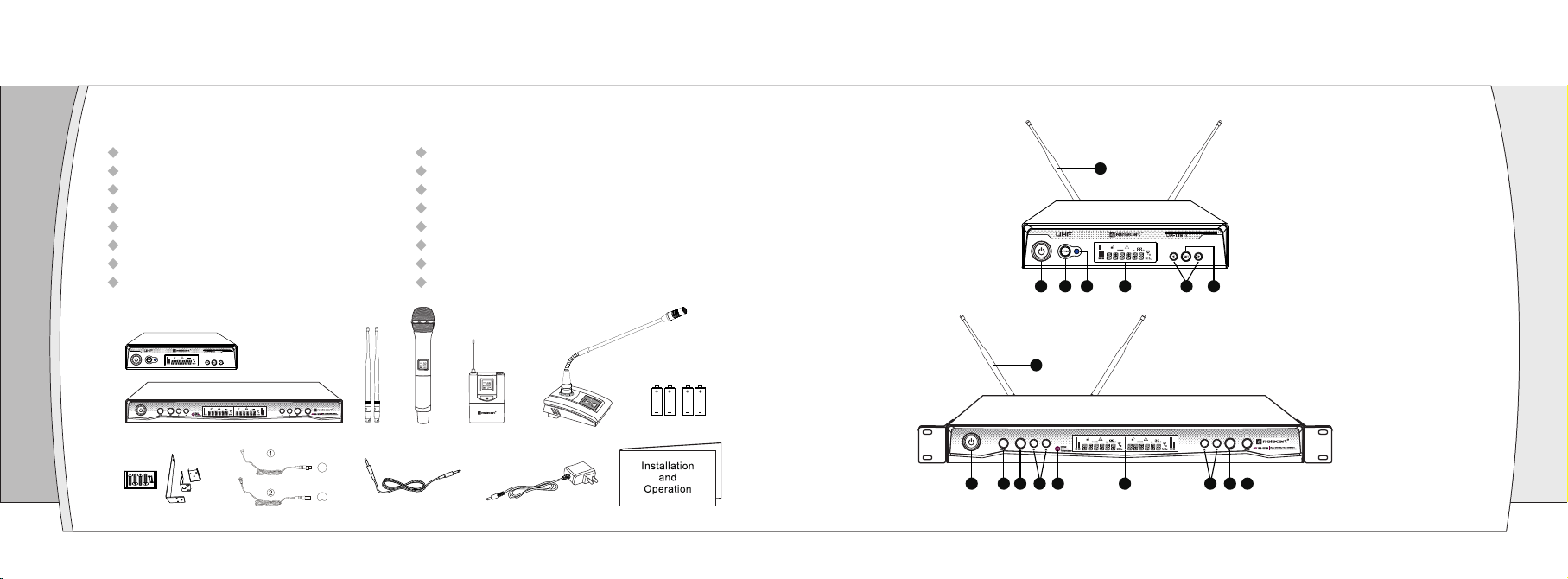
Key Features:
·International EIA STANDARD 1/2U, 1U metal chassis, combined with new-style compact and
elegance LCD display.
·Bright and easy-to-read LCD display shows working frequency or channel, RF/AF, diversity
strengths; transmitter battery level, mute and built-in electronic volume.
·Super wide frequency range UHF 521.25MHz~936.85MHz, automatic frequency selection,
CPU intelligent antenna diversity receiving.
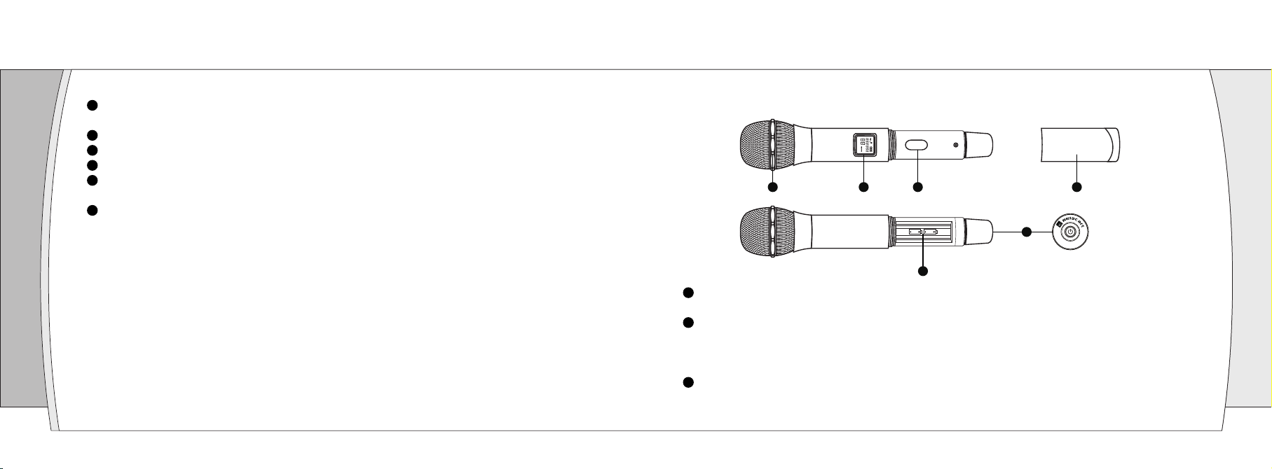
·“AFS” Automatic frequency selection function, Press the “AFS” (Auto Frequency Selection)
button 3S and the receiver will auto-scan and lock on to an open, interference-free frequency.
·Press [IR] button to upload automatically the receiver frequency to the transmitter.
·Stable PLL (Phase Lock Loop frequency control) circuit, combining “IP address” and “NOISE
DETECTION” mute control function, can effectively separate the RF interference from
computer equipment, song machine and DVD in the working environment.
·Four frequency group in total, 40 channels, providing more than 400 adjustable frequency for
the users.
UR-111 Series of condensed the technology essence that Relacart accumulated over a long
period. With advanced technology, sophisticated design, stable performance, with beautiful
appearance, convenient operation and attractive price, with superior professional quality to win
the market competition. This series is suitable for the nightclub of high requirements, multi-
functional hall, hotel, conference room and small to medium performance.