Figure 2
Figure 3
Figure 1
Visit photoexlightingschool.com® for the best free learning resource!
For detailed specifications, product tutorial videos and more, please visit www.photoflex.com®
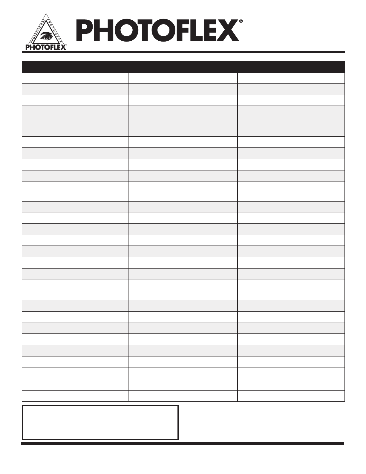
Contents
Safety Precautions ...............................................page 2
Setting up the FlexFlash with Accessories ..........page 2 – 3
FlexFlash Operation..............................................page 4 – 6
Data Sheet ...........................................................page 7
The FlexFlash™ by Photoex is a monobloc, self-contained ash
unit. The power supply and ash head are in one unit, making it
easier to use for location shooting than oor-generator power-
pack type strobes. The FlexFlash utilizes 90 - 260v AC auto
voltage detection for worldwide use.
PLEASE READ AND UNDERSTAND THE SAFETY
PRECAUTIONS AND PRODUCT INSTRUCTIONS
BEFORE USING YOUR FLEXFLASH STROBE.
Safety Precautions
Make sure the power is turned off and the power cord is NOT
plugged into a power receptacle when removing or inserting the
modeling lamp or the ashtube.
Do not touch the ashtube with bare hands. The salts and oils
on your skin will degrade the glass envelope creating a risk of
exploding the ash tube. Use gloves whenever removing or
inserting the ash tube.
Do not use the FlexFlash with a broken ashtube or modeling light.
If the FlexFlash has been dropped or damaged, refer to
Photoex for service before using.
Do not insert screwdrivers or other objects into the housing.
There is risk of electrical shock.
Connect power cord only to 3 pin grounded outlets.
Do not alter the power cord. Removal of ground pin will create an
unsafe environment for using the FlexFlash.
Do not remove the power cord when the power is on as this can
be hazardous.
Do not perform any internal service to the FlexFlash. Please refer
to Photoex for service.
Avoid load imbalance of the strobe head and SoftBox when
mounted on a light stand.
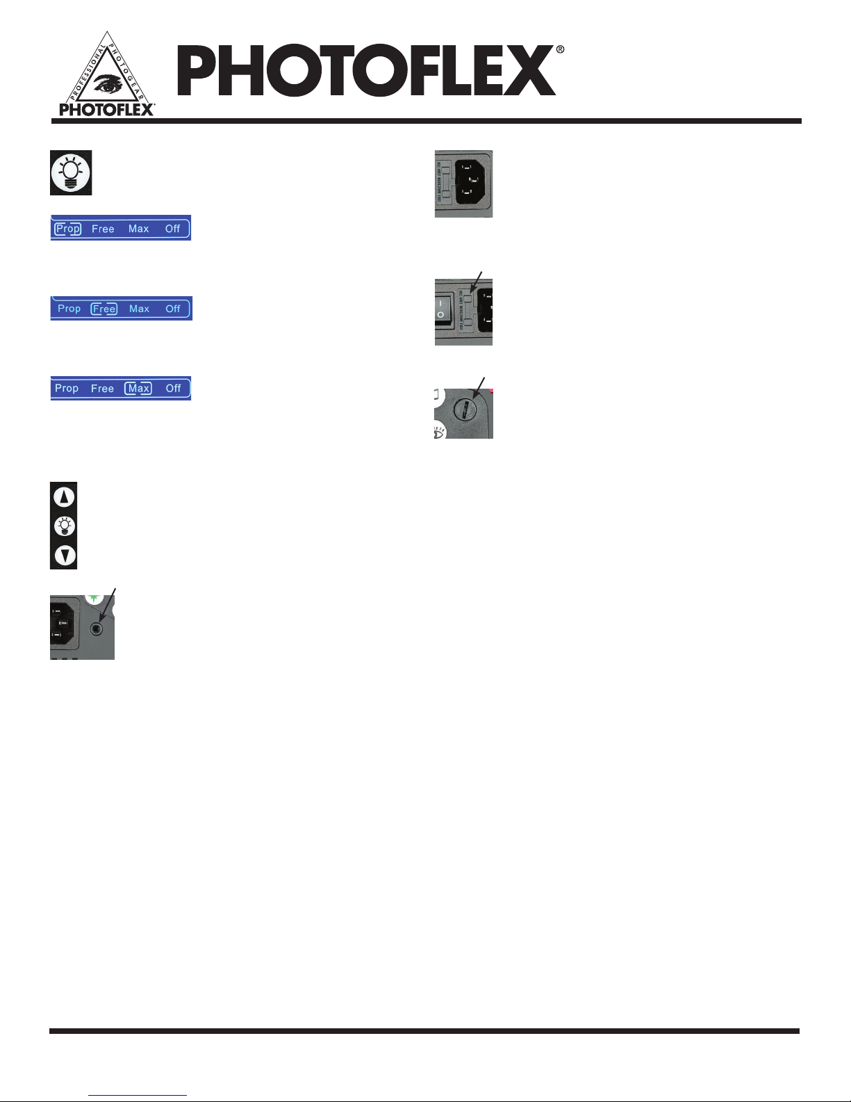
The cover is in place when the
FlexFlash unit is shipped. Before
using the FlexFlash for the rst
time, with the power cord discon-
nected, remove the lamp cover
and install the modeling lamp
which is packaged separately.
The modeling lamp may be left
in the unit after use, however be
sure to allow the lamp to cool
prior to attaching the protective
cover. Figure 2
Notice that the lamp cover has
three square blocks around the perimeter of its base. To put the
lamp cover back in position, line these blocks up with the
corresponding notches in the front collar of the strobe head.
Place the lamp cover blocks into the collar notches, then rotate
the cover clockwise 1/16 turn until the cover locks into position. For
increased lamp protection, we recommend always leaving the lamp
cover in position until you are ready to turn on the FlexFlash unit.
Using Reectors
The FlexFlash includes a seven inch multipurpose reector which
is good for use with umbrellas or by itself for direct lighting
applications. The reector will also accept the seven inch grids
(sold separately, SKU: SB-SFGRIDS). The reectors or any
S-type accessories attach to the FlexFlash in the same manner as
the lamp cover. Notice that the reector has three square blocks
around the perimeter of its base. To put the reector in
position, line these blocks up with the corresponding notches in
the front collar of the strobe head. Push the reector blocks into
the collar notches, then rotate the
reector clockwise about 1/16
turn until it locks into position.
To remove the reector, press
the release button on the top of
the FlexFlash to disengage the
locking mechanism and rotate the
reector counter-clockwise about
1/16 turn; then carefully pull the
reector away from the strobe
unit; avoid contact with ash tube
or modeling lamp. Figure 3
Using SoftBoxes
The FlexFlash can be used with SoftBoxes using the Photoex
Strobe connector SC-B9017TR, which will t all Photoex Soft-
Boxes. To ensure the safest assembly and protect the modeling
lamp and ash tube, it is recommended that the assembled
SoftBox and connector be placed on a clean oor or carpet.
Attach the Flexash to the connector by pushing it down into the
connector, then rotate it clockwise until it locks into place.
To remove the connector and SoftBox assembly, press the
release button on the top of the FlexFlash to disengage the
Setting up the FlexFlash with Accessories
Installing the Modeling Lamp
The FlexFlash comes with a cover
to protect the ashtube and
modeling light. To remove the
lamp cover, press the button on
the top of the FlexFlash to dis-
engage the locking mechanism.
Rotate the lamp cover counter-
clockwise 1/16 turn. Carefully pull
the lamp cover away from the
strobe unit. Figure 1
2