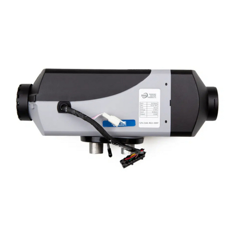
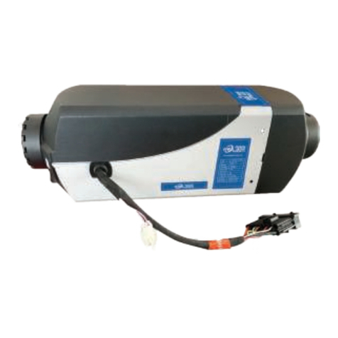
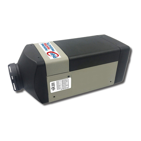
PHP PHP-40A Parts list manual

®
Technical Description
Installation Instructions
Operating Instructions
Maintenance & Troubleshooting
PHP-40A AIR HEATER

2
Table of Contents
Introduction 3
Heater Warnings 4
Specications 5
Heater Kit List 6
Main Components and Operating Concept 8
Heater Mounting 9
Fuel System 13
Electrical Connections 16
Operating Switch 18
Exhaust & Combustion Air Intake Connections 25
Heater Ducting 27
Heater Operation 28
Maintenance 31
Troubleshooting 32
Fault Code Chart 34

3
Introduction
Thank you for purchasing our PHP-40A heater kit.
The PHP-40A heater is designed to provide cabin heating for larger truck sleepers,
o-highway equipment, RVs and boats by using on-board diesel fuel and battery systems.
Operation is simple and the heater provides a safe and reliable alternative to engine idling or
need for electrical plug ins.
Please take a moment to familiarize yourself with this manual, safety warnings and heater
requirements before installing or operating your heater.

4
Heater Warnings
Special Notes
Warning
Caution
Caution - Operational Considerations
Indicates that personal injury or damage to equipment may occur unless specic guidelines
are followed.
Indicates that serious or fatal injury may result if specic guidelines are not followed.
• The installation of this kit requires trained decision making
concerning locating and integrating components, tying
components together, rerouting, or relocating OEM
components, etc. It is impossible to describe all of the
safety and operational considerations in the installation
instructions, therefore, the technician must exercise
professional judgment to achieve a safe and quality
installation.
• Read and understand this manual before attempting to
install the heater.
• Failure to follow all these instructions could cause serious
or fatal injury.
• Exhaust pipe will become very hot during heater
operation.
• Avoid touching exhaust pipe during operation.
• Route exhaust pipe in a manner to shield it from anyone
making contact with it.
This heater is not designed for use with straight bio-diesel
(Blends of bio-diesel up to 10% are acceptable)
Operating outside of these conditions may plug the heater
with soot and result in combustion failure.
This heater is not designed to operate continuously at
altitudes above 1500 meters (4920’).
Operating in these conditions may plug the heater with soot
and result in combustion failure.
• Heater must be turned o while re-fueling.
• Do not install heater in enclosed areas where combustible
fumes may be present.
• Exhaust pipe must maintain a minimum a distance of
50mm (2”) from any ammable or heat sensitive material.
• Ensure there are no leaks in the fuel system.
• Ensure that exhaust fumes cannot enter passenger
compartments.
Warning - Installation Hazards
Warning - Burn Hazards
Bio-Diesel
High Altitudes
Warning - Explosion Hazards
Warning - Fire Hazards
Warning - Asphyxiation Hazards
Note: Highlight areas requiring special attention or clarication.

5
Specications
Principal Dimensions
Performance Specifications
Heating Mode Super High Medium Low
Heating Capacity kW/hr (BTUs/hr) 4.0 (13,500) 3.5 (11,800) 2.1 (7,100) 1.0 (3,412)
Fuel Consumption L/hr (US Gal/hr) 0.5 (0.13) 0.4 (0.10) 0.3 (0.08) 0.11 (0.03)
Air Flow - CFM 80 70 50 30
Power Consumption - watts 40 30 16 12
Power Consumption at Start - watts ≤ 120
Fuel Type Diesel
Nominal Voltage 12 Volt
Lower Voltage Limit 10.5 Volts over 20 seconds
Upper Voltage Limit 16.0 Volt over 20 seconds
Overheat Protection 115º C (239º F)
Allowed Ambient Temperature -40º C to 76º C (-40º F to 168º F)
Weight 4.5 kg (10 lbs)
Above Specications (± 10%)

6
Heater Kit List
QTY
1
1
QTY
1
1
QTY
1
QTY
1
1
2
1
1
QTY
1
1
2
QTY
1
Part Number
P65D-T303
NPN
Part Number
U65A-X702
U65A-X701
Part Number
NPN
Part Number
U65D-X518
U65D-X507
NPN
U65D-X401
NPN
Part Number
NPN
NPN
NPN
Part Number
P40A-T802
Description
Operating Switch
2 Sided Mounting Tape
Description
Mounting Plate
Mounting Plate Seal
Description
Wiring Harness
3.2M (10.5’) Power Harness, 30A Fuse
2.5M (8’) Fuel Pump Harness
2M (6’) Switch Harness
Description
24mm Flexible Stainless Steel Exhaust
25mm Combustion Air Intake Tube
“P” Clamp
24 – 26 mm Exhaust Clamp
16 – 25 mm Hose Clamp
Description
75mm Hot Air Ducting 1M (3’) Length
75mm Air Outlet Adjustable Vent
75mm Hose Clamps
Description
4Kw Air Heater
Heater Only

7
Heater Kit List
QTY
1
1
1
1
1
1
8
Part Number
U65D-X405
P20A-T401
U65D-X407
U65D-X414
U65D-X704
U65D-X403
U65D-X401
Description
Fuel Pickup Tube & Fuel Tube Hardware Kit
- Compression Fitting
- Large Flat Washer
- Small Flat Washer
- Large Rubber Gasket
- Large Hex Nut
- Brass Hex Nut
- Brass Securing Body
Fuel Metering Pump
Fuel Pump Holder
Black Rubber Fuel Line, 0.5M (18”) 5mm ID
“Z” Mounting Bracket
Fuel Line (8m, ID 1.5mm, OD 5mm)
Small Fuel Line Clamps, 9-11 mm
QTY
2
10
8
5
5
2
5
4
4
2
Part Number
NPN
NPN
NPN
NPN
NPN
NPN
NPN
NPN
NPN
NPN
Description
Large Tie Straps
Small Tie Straps
Tek Mount Screws
Self Tapping Screws
Small Flat Washers
Large Flat Washers
M6 Screw
M6 Hex Nuts
Heater Mounting Studs
“L” Brackets

8
Main Components and Operating Concept
3
Application of the PHP-23A Air Heater
The PHP-23A Air Heater is designed to be used as an auxiliary and sometimes primary heater in car, trucks,
RVs, boats, buses, construction and farm equipment. The heater provides heat using the vehicles fuel and
battery power without the need for the vehicle engine to waste fuel by idling just to provide heat. The
PHP-23A Heaters compact design, ease of use, low maintenance and low operating cost make it ideal for
many mobile application where and efficient manner of providing heat is required.
Main Components of PHP-23A Air Heater
1) Process Air Blower Wheel 6) Blower Motor C. Combustion Air
2) Electronic Control Unit 7) Glow Pin E. Exhaust Gas
3) Combustion Air Blower Wheel 8) Heat Exchanger F. Fresh / Process Air Intake
4) Combustion Chamber 9) Fuel Pump H. Hot / Process Air Outlet
5) Overheat / Flame Sensor
10) Operating Unit / Controller
D. Fuel Intake
How the PHP-23A Air Heater Works
The external fuel pump delivers fuel to the combustion chamber, the blower motor delivers outside
combustion air to the burner chamber and a glow pin is used to ignite the fuel-air mixture to create heat.
The heat from the burner is transferred into the heat exchanger while the exhaust gases are expelled to the
exterior of the vehicle. The process air from the area to be heated is circulated through the heater over the
outside of the heat exchanger with the blower wheel which warms the interior of the vehicle. The heater
automatically maintains the desired set temperature in the vehicle to keep the operator and or passengers
comfortable.
• The fuel pump delivers fuel to the combustion chamber.
• The combustion air blower delivers air to the combustion chamber.
• A glow pin is used to ignite the fuel-air mixture.
• The heat from the ame is transferred through the heat exchanger while the exhaust
gases are expelled to the exterior of the vehicle.
• The process air blower transfers air from the cabin, over the outside of the heat
exchanger and blows hot air into the cabin.
• The heater automatically maintains the desired set temperature in the cabin by
regulating through multiple heat output modes.
10

9
Heater Mounting
6
Installation Instructions and Regulations
Please Note:
Failure to comply with the regulations, safety instructions, installation instructions or having repairs
performed by unauthorized persons or use of aftermarket parts voids the heater warranty and relieves the
manufacturer, distributors, dealers, and installation technicians from any and all liabilities.
The installer is responsible for all damages to the property or person that arises from faulty installation of the
heater.
Choosing Heater Location and Position
The location to mount the heater in the vehicle will vary depending on the application. Typically the heater
should be mounted on the floor in a protected area. Commonly they are mounted in the storage
compartment under the bed in a transport truck cab or under the seat in a passenger vehicle. The heater
can also be mounted on walls and or in protected compartments outside the operator / passenger cabin as
long as all the installation instructions and regulations are followed. When considering the location to
mount the heater you must take into account the following concerns.
There must be enough clearance around the heater, heater ducting and the exhaust to avoid any
damage to heat sensitive materials or vehicle components.
The heater must not be exposed to the outside elements and in cases where it is mounted outside
the vehicle cabin it must be properly enclosed and protected.
The mounting surface must be such that it is possible to get a complete seal between the heater and
the floor or the heater mounting plate and the floor.
The heater must not be exposed to excessive heat and or any fuels, oils or other potentially
hazardous chemicals or materials.
Tolerable swivel range
Depending on the installation conditions, swivel angles are allowed as shown below:
Please Note:
The glow pin must remain on the upper or top side position.
During use, the heater can deviate from the shown normal or maximum installations positions by up to 15°
in all directions in order to accommodate the vehicle or boat movement.
Typically, air heaters are mounted inside a tool compartment with the OEM HVAC System.
However, the heater may be mounted anywhere inside the cabin provided you adhere to the
following conditions:
• Combustion air intake, exhaust and fuel inlet connections must be on outside of the
vehicle.
• Heater must be mounted on at surface and provide an air tight seal between heater
and vehicle.
• Refer to Figure M1 for permissible mounting orientations.
Heater Location
Figure M1

10
Heater Mounting
• A mounting plate and hardware are provided with the truck heater kit.
• Refer to Figures M2 & M3 for assembly orientation. Note: If the mounting plate will not
be used, the heater ange can be used as a template to mark where the individual
components openings should be made.
• For ease of installation fasten the mounting plate to the heater and make exhaust,
combustion air intake and fuel connections at the base of the heater before mounting
the assembly to the vehicle.
• Cut a two 3”holes or a 4”x 5” rectangular opening on the cabin oor to accommodate
mounting plate and seal. Refer to Figure M4.
• Secure mounting plate to vehicle with self taping “Tek” screws provided.
Mounting
Figure M2

11
Heater Mounting
Figure M3
Combustion air
Seal
Exhaust
Fuel Line
Wiring Harness
Heater Flange
22
Parts Diagram of PHP-23A Air Heater

12
Heater Mounting
Figure M4
2 1/8”
Ø3” x 2
4” x 5”
Rectangle
++

13
Fuel System
The PHP-40A fuel pump and fuel system are the heart of the heater. The fuel pump not only delivers fuel
to the heater but also controls the amount of fuel delivered. The pump is designed to operate like an
electric solenoid and works using electric pulses. Each time it is energized, it provides a measured dose of
fuel. It is critical to the heater’s operation to stay within parameters outlined in Figure F1 and only use the
components provided.
System Layout & Considerations
• Keep the length of the fuel system short as possible.
• Mount the fuel pump as close to the fuel pickup as possible (pump pushes better than it sucks).
• Minimize vertical rise.
• Mount the fuel pump in a protected location away from road spray.
• Choose a mounting location for the fuel pickup pipe that is close to the heater and oer installation
access.
• Design your fuel system so that Figure F1 fuel line limits are not exceeded.
Figure F1
1. Heater
2. Fuel Pickup Pipe
3. Fuel Metering Pump
4. Fuel Tank
5. 9-11 mm Clamp
6. 5.0 mm Rubber Fuel Line
7. 5.0 mm Rubber Connector
8. 1.5 mm Clear Plastic Fuel Line

14
Fuel System
Fuel Pump Mounting
• Using the bracket and rubber mount provided, install fuel pump as shown in Figure F2.
• Isolating the pump with the rubber holder helps to minimize noise created during operation.
• Ensure that the proper mounting angle is observed to avoid cavitation. (Figure F3)
Fuel Source
• Connect directly into the fuel tank using our dedicated fuel pickup tube. (Figure F4)
• Teeing into the existing vehicle fuel lines is not recommended.
• There are three common methods to install a fuel pickup tube.
o Use NPT / compression ttings if available
o Use spare fuel gauge plate if available
o Drill dedicated holes into the tank.
Fuel Pickup Pipe
Figure F2 Figure F3
13
Mount the Fuel Pick Up Pipe into the tank in the order shown below.
Please Note:
To avoid dropping the compression fitting and base into the fuel tank, make sure it is tightened onto the pipe
before putting pipe into tank.
Be careful not to let go of the fuel pipe and drop it into the fuel tank while assembling components onto fuel
pipe.
Electrical System Installation
The heater harness that comes with the heater has all the electrical connections preassembled for easy
installation. Secure any excessive length of cables in a protected spot.
To route the cables to the fuel pump and the batteries use either an existing cable passage or drill a hole
near the heater to route the cables outside. Make sure to seal the hole around the cables and make sure
they are protected from chaffing or damage during vehicle movement.
When installing the controller it may be necessary to remove the terminals from the connector in order to
route them through the small hole in the mounting surface. Be extremely careful not to damage the
terminals or connector and make sure the wires are reinstalled in the correct positions.
Safety Warnings for Electrical Wiring
Before installing the harness remove the main 15 or 20 Amp fuse until the wiring is completely installed to
avoid accidentally shorting the wiring during assembly. Remember to reinstall when starting heater.
Ensure that the electric cables or insulation and connectors are not damaged prior to installation and be
careful not to pinch or damage cables and connectors during installation.
Be sure to consider the movements of the vehicle cab when installing and securing the harness to the fuel
pump and batteries and leave enough excess play in the harness to avoid pulling on or damage to the
harness.
Lubricate all outside connections with contact grease to avoid corrosion.
Figure F4

15
Fuel System
Fuel Pick-Up Pipe Installation (Drill Option)
• Drill mounting holes in tank to accommodate pick-up pipe as shown in Figure F4
• Drill the two (1/4”) holes rst as shown in Figure F5.
• Drill a 7/8” hole as shown in Figure F6.
• Mount the fuel pick-up assembly pipe as shown in Figure F4.
• Position fuel pick-up 4” from bottom of tank for round tanks and 1” for at tanks (cut tube as
necessary)
Fuel Line Connections
• Route fuel lines from the fuel pick-up pipe to the heater.
• Use only fuel lines provided (Other sizes or types of fuel lines may inhibit proper fuel ow)
• Make proper butt joints using clamps and connector pieces as shown.
• Use a sharp utility knife to cut plastic fuel lines to avoid fuel line pinching.
Figure F6Figure F5

16
Electrical Connections
Fuel Pump
Battery
Operating Switch
Heater
30 amp Fuse
Electrical System Installation
The heater harness has all the electrical connections preassembled for easy installation.
• Route cables using either an existing cable passage or drill holes as required.
• Seal the hole around the cables and make sure they are protected from chang and pinching.
• Below is a summary of the wiring connections required.
A. Main Heater Harness Connects switch and power harness to the heater harness.
Refer to Main Harness Connections Legend for details.
B. Power Harness 2 Core, 3.2M (10.5’) Long – Red/White (+) & Black/White (-)
• Route power harness section from heater to vehicle batteries.
• Connect red/white wire to battery (+).
• Connect black/white wire to battery (-).
• Install 30 amp main fuse (Last step of installation)
C. Switch Harness 4 Core, 2M (6’) Long – Red, White, Green, Blue
• Route switch harness section from heater to switch location.
• Attached connector to operating switch
D. Fuel Metering Pump Harness 2 Core, 2.5M (8’) Long – Yellow, Yellow
• Route fuel metering pump harness to fuel pump.
• Connect to fuel pump
Figure E1

17
Electrical Connections
Main Harness Wiring Legend
Note: There are no corresponding numbers on the connector.
Numbers are for reference only.
Terminal Wire Color Function
1. White Switch
2. Blue Switch
3. Yellow Fuel Pump
4. Red / White Main Power “+”
5. Red Switch
6. Green Switch
7. Yellow Fuel Pump
8. Black Main Power “-”
Open end view of main heater harness connector
Figure E4
Green
Red
Blower Motor
Glow Pin
Flame / Overheat
Sensor
Main Harness Access
Black
Yellow
Black
Black
Open
1
5
2
6
3
7
4
8

18
Operating Switch
The PHP-40A is provided with a multifunctional controller. It is capable of manual and timer controlled
switching of the heater and conveys heater operational parameters and diagnostics. Refer to the Operating
Switch Instructions for operational details.
Mount the operating switch in a suitable location.
It should be located where it will be accessible to the operator and be able to sense the temperature of the
cabin area being heated.
Route the harness from the heater to the switch location.
Remove the 4 screws and backing plate and connect harness as shown in Figure F3.
Re-attach backing plate then mount the operating switch using either two mounting screws or two sided
tape.
Notes:
All exposed electrical connections should be coated with protective grease.
To avoid accidental shorting, connect the heater to the battery and install the fuse as the last step.
This should only be completed once all other installation steps are completed.
Caution
Figure E2
Figure E3

19
Operating Switch
PHP Gen II Air Heater Control Switch - Operation Instructions
Overview:
The PHP Control Switch allows you to set and regulate temperature, set operating mode, timed shutdown
and timed startup functions. It also facilitates troubleshooting by providing diagnostic codes.
PHP Gen II Air Heater Control Switch - Operation Instructions
Overview:
The PHP Control Switch allows you to set and regulate temperature, set operating mode, timed
shutdown and timed startup functions. It also facilitates troubleshooting by providing diagnostic
codes.
Operation Buttons and Display Icons:
Programming Keys:
1. On / Off & Select
2. Operation Status
3. Switch Modes
Display Icons and Terms:
1. Heating Mode
2. Degrees Celsius
3. Manual Mode
4. Automatic Climate Mode
5. Indicates Time
6. Indicates Error
On / Off Control:
Press and hold 3 sec. to start heater displays and heater begins start-up
Press and hold 3 sec. to stop heater display flashes during 5 minute cool
down then disappears and heater shuts
down.
20
ºC
GEAR
A/C
TIM
Error

20
Operating Switch
Operating Modes:
The heater is designed to function in two dierent operating modes.
“Gear” mode (Manual) allows you to control the heater output mode in 4 operating levels.
“Automatic Climate - A/C”mode allows you to control the target cabin temperature that the heater will
maintain. This is the more common operating mode and is practical for use with cargo and cabin heating
applications. This mode allows you to set the target cabin temperature from 8°C to 36°C (As measured at the
Control Switch).
Note: The heater will initially start in “Gear” Mode.
PHP Gen II Air Heater Control Switch - Operation Instructions
Operating Modes:
The heater is designed to function in two different operating modes.
“Gear” mode (Manual) allows you to control the heater output mode in 4 operating levels.
“Automatic Climate - A/C” mode allows you to control the target cabin temperature that the
heater will maintain. This is the more common operating mode and is practical for use with cargo
and cabin heating applications. This mode allows you to set the target cabin temperature from 8ºC
to 36ºC (As measured at the Control Switch).
Note: The heater will initially start in “Gear” Mode.
Switching Operating Modes
To switch heater between Gear Mode and Automatic
Temperature Control Mode the heater must first be
started.
Switch between modes by pressing
Heater will alternate between two operating modes.
For A/C Mode:
A/C and Temperature displayed in °C
For Gear Mode:
Gear, Gear Level and Temperature
displayed in °C
Gear (Manual) Mode Setting - Heater Turned On
Heater will start in Gear mode.
This mode allows you to set the desired heat output /
gear level 1, 2, 3, or 4 (Low to High)
To switch between Heat Output / Gear Levels:
Rotate Clockwise or Counterclockwise
In a snapping motion.
Desired heat output level
Will be displayed with 1, 2, 3, or 4
(Low to High)
Automatic Temperature Control Setting - Heater Turned On
Change desired temperature setting from 8º to 36º:
Rotate Clockwise or Counterclockwise
In a snapping motion
A/C and Temperature set point will be
displayed in °C
Temperature set point will flash during
adjustment then revert to current cabin
temperature display.
GGEEAARR
20
º A/C
20
º
20
º
A/C
20
º
GEAR
Table of contents
Other PHP Heater manuals