phytron phyMOTION POWM01.2 User manual

phytron
10/2015 Manual MA 1273-A007 EN
phyMOTIONTM
Power Supply Modules
POWM01.2, POWM02.2,
POWM03.1 and POWM04.1
TRANSLATION OF THE ORIGINAL GERMAN MANUAL

Manual POWM01 / POWM02 / POWM03 / POWM04
MA 1273-A007 EN 2
©2015
All rights with:
Phytron GmbH
Industriestraße 12
82194 Gröbenzell, Deutschland
Tel.: +49(0)8142/503-0
Fax: +49(0)8142/503-190
Intention of the manual:
In this manual you will find descriptions and specifications of the phyMOTIONTM module:
Power Supply POWM01, POWM02, POWM03 and POWM04
This manual is a supplementary volume to the operating instructions
phyMOTIONTM Modular Multi-axis Controller for Stepper Motors
In the manual phyMOTIONTM Modular Multi-axis Controller for Stepper Motors
(http://www.phytron.de/phyMOTION) are the descriptions of the features and specifications
for the phyMOTIONTM stepper motor controller.
Every possible care has been taken to ensure the accuracy of this technical manual. All
information contained in this manual is correct to the best of our knowledge and belief but
cannot be guaranteed. Furthermore we reserve the right to make improvements and
enhancements to the manual and / or the devices described herein without prior
notification.
We appreciate suggestions and criticisms for further improvement.
Email address: doku@phytron.de
Questions about the use of the product described in the manual that you cannot find
answered here, please contact your representative of phytron (http://www.phytron.eu/) in
your local agencies.

phytron
3 MA 1273-A007 EN
1 Legal Instructions
i
This manual:
Read this manual very carefully before mounting, installing and operating the
device and if necessary further manuals related to this manual.
- Please pay special attention to instructions that are marked as follows:
DANGER –
Serious injury!
Indicates a high risk of serious injury or
death!
DANGER –
Serious injury from
electric shock!
Indicates a high risk of serious injury or
death from electric shock!
WARNING –
Serious injury
possible!
Indicates a possible risk of serious injury or
death!
WARNING –
Serious injury from
electric shock!
Indicates a possible risk of serious injury or
death from electric shock!
CAUTION – Possible
injury!
Indicates a possible risk of personal injury.
i
CAUTION – Possible
damage!
Indicates a possible risk of damage to
equipment.
CAUTION – Possible
damage due to ESD!
Refers to a possible risk of equipment
damage from electrostatic discharge.
i
”Any heading“ Refers to an important paragraph in the
manual.

Manual POWM01 / POWM02 / POWM03 / POWM04
MA 1273-A007 EN 4
Observe the following safety instructions!
Qualified personnel
WARNING – Serious injury possible!
Serious personal injury or serious damage to the machine and drives could be
caused by insufficiently trained personnel!
Without proper training and qualifications damage to devices and injury might
result!
- Design, installation and operation of systems may only be performed by
qualified and trained personnel.
- These persons should be able to recognize and handle risks emerging
from electrical, mechanical or electronic system parts.
- The qualified personnel must know the content of this manual and be
able to understand all documents belonging to the product. Safety
instructions are to be provided.
- The trained personnel must know all valid standards, regulations and
rules for the prevention of accidents, which are necessary for working
with the product.

phytron
5 MA 1273-A007 EN
Safety Instructions
Further Manual
This manual is an addition to the following main manual:
“phyMOTIONTM Modular Multi-axis Controller for Stepper Motors”
- First, read the main manual and then continue with this manual.
i
Intended use:
The phyMOTIONTM is designed for operating in a drive system.
- An installation is allowed only if the requirements of the EC Machinery
and EMC Directives are conformed with.
i
Part of a machine:
This product is used as a part of a complete system, therefore risk
evaluations concerning the specific application must be made before using
the product.
- Safety measures have to be taken and verified according to the
results of risk evaluation.
- Personnel safety must be ensured by the concept of this overall system
(e.g. machine concept).
WARNING – Serious injury from electric shock!
If the phyMOTIONTM is not operated with SELV/PELV voltages, the risk of
dangerous voltages may be on the device. Touching these components
carrying high voltages can cause serious injury or death from electric shock:
- Always observe the safety concept SELV / PELV to ensure safe
isolation and separation of low voltage supplies from the mains.
WARNING – Serious injury from electric shock!
During electrical installation cables, connectors, etc. can be live.
- Before starting wiring, make sure that none of the power supplies
are connected to the primary side of the mains supply. Isolate the
power supplies from the mains or remove the appropriate fuses.
- All modules must be inserted and screwed into the phyMOTIONTM
housing before powering up. If necessary, unoccupied module slots
must be covered with the supplied blank front plates.
Never operate the equipment when open.
- Do not plug or unplug the modules while powered.
- Do not plug or unplug the connectors while powered.
- If the equipment was energised, wait 3 minutes after power off to
allow the capacitors to discharge and ensure that there are no
residual charges on cables, connectors and boards.

Manual POWM01 / POWM02 / POWM03 / POWM04
MA 1273-A007 EN 6
2 Contents
1Legal Instructions .................................................................................................... 3
2Contents.................................................................................................................... 6
3POWM – Power Supply of the phyMOTIONTM ........................................................ 7
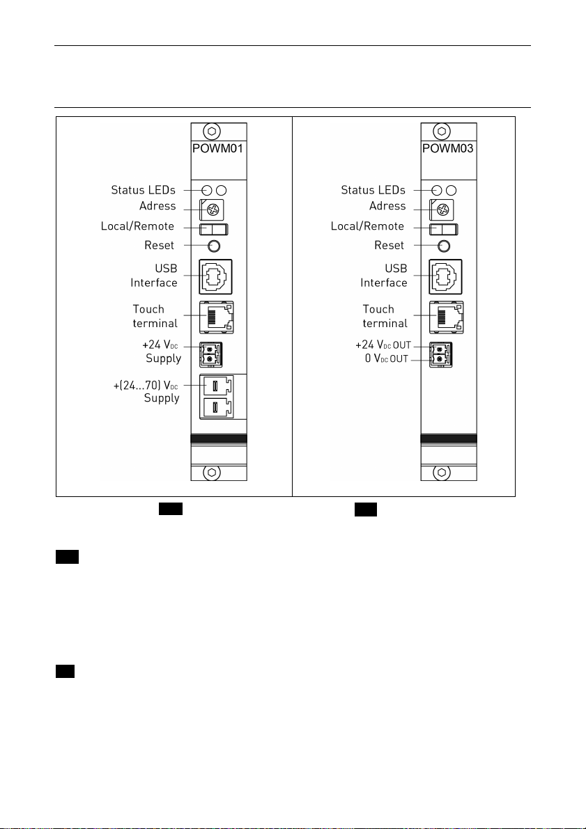
4Module Overview...................................................................................................... 8
4.1 Main supply POWM01 and POWM03 ..................................................................8
4.2 Intermediate supply POWM02 and POWM04.................................................... 10
5Technical Data ........................................................................................................ 11
5.1 Declaration of Incorporation: Modules gen. and ext. Supply EXT..................... 11
5.2 Declaration of Incorporation: Modules with internal Supply INT......................... 13
5.3 Mechanical Data................................................................................................. 15
5.4 Features POWM01 and POWM03 ..................................................................... 16
5.5 Features POWM02 and POWM04 ..................................................................... 18
4.5 Functions............................................................................................................. 20
6Installation .............................................................................................................. 21
6.1 Mechanical Installation ....................................................................................... 21
6.1.1 Assembly Rules........................................................................................... 23
6.2 Electrical Installation........................................................................................... 25
6.2.1 Connectors – Overview ............................................................................... 25
6.2.2 Pin Assignment POWM02 and POWM04 ................................................... 26
6.2.3 Pin Assignment POWM01........................................................................... 27
7Commissioning ...................................................................................................... 30
7.1 USB Driver Installation (Windows) ..................................................................... 31
7.2 DIP Coded Rotary Switch................................................................................... 32
7.3 REMOTE/LOCAL Switch R/L ............................................................................. 32
7.4 Diagnostic by LED Display ................................................................................. 33
7.5 Reset Button....................................................................................................... 33
8Parameterising the Module ................................................................................... 34
9Service..................................................................................................................... 35
10 Version / Compatibility .......................................................................................... 35
11 Warranty, Disclaimer and Registered Trademarks .............................................36
11.1 Disclaimer...................................................................................................... 36
11.2 Warranty........................................................................................................ 36
11.3 Registered Trademarks................................................................................. 36
12 Index ........................................................................................................................ 37

phytron
7 MA 1273-A007 EN
3 POWM – Power Supply of the phyMOTIONTM
POWM stands for “Power Module“. POWM01 and POWM02 are used for the
phyMOTIONTM with external supply EXT, POWM03 and POWM04 for the phyMOTIONTM
with internal supply INT .
POWM01 and POWM02 EXT include the external power supply for the power stages (24
VDC to 70 VDC) as well as the power supply for the I/Os and the limit switches (isolated 24
VDC). The supply voltage for the power stages (24 VDC to 70 VDC) also generates the
internal logic supply of 5 V.
POWM03 and POWM04 INT direct the supply voltages, which are generated internally,
for the power stages (48 VDC / 70 VDC), as well as the power supply for the I/Os and the
limit switches (isolated 24 VDC) and the internal logic voltage of 5 V.
Each power module can supply a maximum of 10 more modules.
The main power modules POWM01and POWM03 contain additional features for the
configuration of the phyMOTIONTM.
Fig. 1: Wiring diagram of the phyMOTIONTM with internal supply INT
Fig. 2: Wiring diagram of the phyMOTIONTM with external supply EXT

Manual POWM01 / POWM02 / POWM03 / POWM04
MA 1273-A007 EN 8
4 Module Overview
4.1 Main supply POWM01 and POWM03
Fig. 3: POWM01 EXT POWM03 INT
EXT: POWM01 Feed-in to the power supply:
•24 to 70 VDC supply voltage (for motors and generates internally the logic voltages) –
20 A max.
•Optional electrically isolated 24 VDC for inputs/outputs, limit and reference switches
The external supply must be designed for the required current (e.g. by the SPH 240-
2410-24 power supply unit).
INT: POWM03 For looping through the supply voltages:
•48 / 70 VDC supply voltage (for motors and generates internally the logic voltages) –
20 A max.
•Optional electrically isolated 24 VDC for inputs/outputs, limit and reference switchesr
•24 VDC output (for i.e. sensors)

phytron
9 MA 1273-A007 EN
Configuration:
•USB interface for programming and diagnostics
•Device address switch
•Remote/Local switch
•Reset button
•Connection of an external phytron touch panel

Manual POWM01 / POWM02 / POWM03 / POWM04
MA 1273-A007 EN 10
4.2 Intermediate supply POWM02 and POWM04
Fig. 4: POWM02 EXT POWM04 INT
EXT: Feed-in to the power supply:
•24 to 70 VDC supply voltage (for motors and generates internally the logic voltages)
– 20 A max.
•Optional electrically isolated 24 VDC for inputs/outputs, limit and reference switches
INT:For looping through the supply voltages:
•24 bis 70 VDC Versorgungsspannung (für Motoren und internes Erzeugen der
Logikspannungen) – max. 20 A
•Galvanisch getrennte 24 VDC für Ein-/Ausgänge, sowie End- und Referenzschalter
•24 VDC Ausgang (für z.B. Sensoren)
Configuration:
The POWM02 and POWM04 are purely an intermediate supply and thus provide no
configuration interface.

phytron
11 MA 1273-A007 EN
5 Technical Data
5.1 Declaration of Incorporation: Modules gen. and ext. Supply EXT

Manual POWM01 / POWM02 / POWM03 / POWM04
MA 1273-A007 EN 12

phytron
13 MA 1273-A007 EN
5.2 Declaration of Incorporation: Modules with internal Supply INT

Manual POWM01 / POWM02 / POWM03 / POWM04
MA 1273-A007 EN 14

phytron
15 MA 1273-A007 EN
5.3 Mechanical Data
Dimension 100 x 100 mm without front panel
Weight POWM01: 68 g / 90 g (without/with front panel)
POWM02: 53 g / 86 g (without/with front panel)
POWM03: 63 g / 85 g (without/with front panel)
POWM04: 48 g / 81 g (without/with front panel)
Mounting Plug-in module into the modular stepper motor controller
phyMOTIONTM
POWM01/02/03/04 modules are exclusively for mounting in
the specially designed power slots.
Mounting position vertical

Manual POWM01 / POWM02 / POWM03 / POWM04
MA 1273-A007 EN 16
5.4 Features POWM01 and POWM03
Features
Power supply 24…70 VDC / 20 A max. (motor supply UB)
+24 VDC (±20 %) electrically isolated / 5 A max. (I/O supply)
POWM01 EXT
24…70 VDC / max.20 A (motor supply UB)
+24 VDC (±20%) electrically isolated / max. 5 A (I/O supply)
POWM03 INT
48 / 70 VDC / max.20 A (motor supply UB)
+24 VDC (±20%) electrically isolated / max. 5 A (I/O supply)
+24 VDC output voltage i.e. for sensors
Voltage range POWM01
between 24…70 VDC and 24 VDC I/O
POWM03
between 48 / 70 VDC and 24 VDC I/O
Current capacity 20 A max. / UB, 5 A max. / +24 VDC
The total current at + 24VDC for all inputs / outputs, as well
as limit and reference switches, encoders and sensors incl.
the 24 VDC tap of POWM03 / 04 modules must not exceed
the value of 5 A per total phyMOTIONTM.
Power loss POWM01 / POWM03
1400 mW at UB= 70 VDC
Over voltage protection no
Short circuit protection Logic voltage (5 V): auto-reset 2.6 A
UB: 2 x 10 A
Diagnostics 2 status LEDs on the front panel
Switch/button DIP switch for adjusting the controller’s address
Remote/Local switch
Reset button

phytron
17 MA 1273-A007 EN
Interfaces
24-70 VDC Motor-Supply
(POWM01)
24 VDC to 70 VDC input range for the supply of the power
stages and for generating the internal logic supply.
24 VDC I/O-Supply
(POWM01)
Separate 24 VDC for the supply of I/Os (e.g. digital
inputs/outputs of the DIOM01), limit and reference switches
(e.g. on the I1AM01, INAM01 and EXAM01).
24 VDC Output voltage
(POWM03)
24 VDC supply i.e. for sensors
max. 5 A/+24 VDC
USB USB interface for parameterising and programming of the
phyMOTIONTM.
Touch panel 4 pin Western modular connector flat oval 4p/4K for the
connection of an external touch panel
Bus connection rear panel Module supply of the phyMOTIONTM
5 VLogic: 2 A max.
The number of connected modules after a POWM01 or POWM03 depends on the total
current of all modules in a voltage group. This sum may not exceed the maximum current
capacity (20 A)!

Manual POWM01 / POWM02 / POWM03 / POWM04
MA 1273-A007 EN 18
5.5 Features POWM02 and POWM04
If the total current of all modules in a voltage group (20 A) is exceeded, or if a voltage
group has various voltages to begin with, the POWM02 and POWM04 module must be
applied for the supply of the power stages and I/Os.
A power module can be inserted only in designated slots. These slots must be already
defined before ordering the phyMOTIONTM.
Features
Power supply POWM02 EXT
24…70 VDC / max.20 A (motor supply UB)
+24 VDC (±20%) electrically isolated / max. 5 A (I/O supply)
POWM04 INT
48 / 70 VDC / max.20 A (motor supply UB)
+24 VDC (±20%) electrically isolated / max. 5 A (I/O supply)
+24 VDC output voltage i.e. for sensors
Voltage range POWM02
between 24…70 VDC and 24 VDC I/O
POWM04
between 48 / 70 VDC and 24 VDC I/O
Current capacity max. 20 A / UB, max. 5 A / +24 VDC
The total current at + 24VDC for all inputs / outputs, as well as
limit and reference switches, encoders and sensors incl. the
24 VDC tap of POWM03 / 04 modules must not exceed the
value of 5 A per total phyMOTIONTM.
Power loss POWM02 / POWM04
1400 mW at UB= 70 V
Over voltage protection no
Short circuit protection Logic voltage (5 V): auto-reset 2.6 A
UB: 2 x 10 A
Diagnostics 2 status LEDs on the front panel

phytron
19 MA 1273-A007 EN
Interfaces
24–70VDC Motor-Supply
(POWM02)
24 VDC to 70 VDC input range for the supply of the power
stages and for generating the internal logic supply.
24 VDC I/O-Supply
(POWM02)
Separate 24 VDC for the supply of I/Os (e.g. digital
inputs/outputs of the DIOM01), limit and reference switches
(e.g. on the I1AM01, INAM01 and EXAM01).
24 VDC Output voltage
(POWM04)
24 VDC supply i.e. for sensors
max. 5 A/+24 VDC
Bus connection rear
panel
Module supply of the phyMOTIONTM
5 VLogic: max. 2 A
The number of connected modules after a POWM02 and POWM04 depends on the total
current of all modules in a voltage group. This sum may not exceed the maximum current
capacity (20 A)!

Manual POWM01 / POWM02 / POWM03 / POWM04
MA 1273-A007 EN 20
4.5 Functions
POWM01 and POWM02:
Feed-in to the power supply:
•24 to 70 VDC supply voltage (for motors and generates internally the logic
voltages) – 20 A max.
•Optional electrically isolated 24 VDC for inputs/outputs, limit and reference switches
POWM03 and POWM04:
Feed-in to the power supply:
•48 and 70 VDC supply voltage (for motors and generates internally the logic
voltages) – 20 A max.
•Optional electrically isolated 24 VDC for inputs/outputs, limit and reference switches
•+24 VDC output voltages i.e. for sensors
The total current at + 24VDC for all inputs / outputs, as well as limit and reference
switches, encoders and sensors incl. the 24 VDC tap of POWM03 / 04 modules must
not exceed the value of 5 A per total phyMOTIONTM..
Only POWM01 and POWM03:
Configuration:
•USB interface for programming and diagnostics
•Device address switch for setting a fixed bus address
(is necessary e.g. with RS 485, CAN etc.)
•Remote/Local switch for switching the mode from Remote (controller receives the
commands via HOST interface) to Local (the controller is running in pure
stand-alone mode with a sequential program).
•Reset button for the resetting of the controller
•Connection of an external phytron touch panel (e.g. Android-based tablet)
This manual suits for next models
3
Table of contents
Other phytron Power Supply manuals
Popular Power Supply manuals by other brands

Paso
Paso PM2010 Instructions for use

Sorensen
Sorensen XBT32-3FTP Operation manual

Moritex Schott
Moritex Schott MLEP-A035W1LR instruction manual

Emerson
Emerson NetSure 710NPBA installation instructions

Vertiv
Vertiv NetSure-48 VDC Power System 502NGFB Installation and user manual

Abatron
Abatron BDI2000 installation manual