2
www.phywe.com, © All rights reserved 12918-00 / 4119
3 FUNCTIONAL AND OPERATING ELEMENTS
3.1 Operating elements
The sensor has a power button and several LEDs, the func-
tion of which is explained in the following.
On-button
To switch the sensor on and off in Bluetooth mode, the power
button must be pressed for longer than 3s. If the sensor is to
be connected via USB, it is not necessary to press the power
button.
Bluetooth-LED
Battery charge LED
Charging process
completed
Work-Indicator-LED
3.2 USB port
The battery, which is permanently installed in the sensor, is
charged via the type C USB port. Furthermore, communica-
tion with a computer takes place via this interface.
4 NOTES ON OPERATION
This device fulfils all of the technical requirements that are
compiled in current EC guidelines. The characteristics of this
product qualify it for the CE mark.
The individual connecting leads are each not to be longer
than 2 m.
The instrument can be so influenced by electrostatic charges
and other electromagnetic phenomena (HF, bursts, indirect
lightning discharges) that it no longer works within the given
specifications. Carry out the following measures to reduce or
eliminate the effect of such disturbance: Ensure potential
equalization at the PC (especially with Laptops). Use screen-
ing. Do not operate high frequency emitters (e.g. radio
equipment or mobile radiotelephones) in the immediate vicini-
ty. When a total failure of the instrument occurs, unplug it and
plug it back in again for a reset.
5 HANDLING
This section describes the start-up of the sensor and the re-
cording of measurement data. Please read this section thor-
oughly in order to avoid failures or operating errors.
5.1 Charging process
Use a USB-C cable to connect the sensor to a computer or
USB charger (not included).
During the charging process, the battery charge LED lights
up red. When the charging process is complete, the battery
charge LED lights up green. The charging time for a com-
pletely discharged battery is 3 hours maximum.
Disconnect the charger at the latest four hours
after the completion of the charging process. Oth-
erwise, the service life of the battery may be neg-
atively affected.
5.2 Start-up
Switch on the sensor by pressing the power button for more
than 3s. Now the Bluetooth LED flashes red. Start the soft-
ware and select the sensor.
If the sensor is to be used via the USB interface, it does not
need to be switched on. The sensor is connected directly to
the end device using the supplied USB cable.
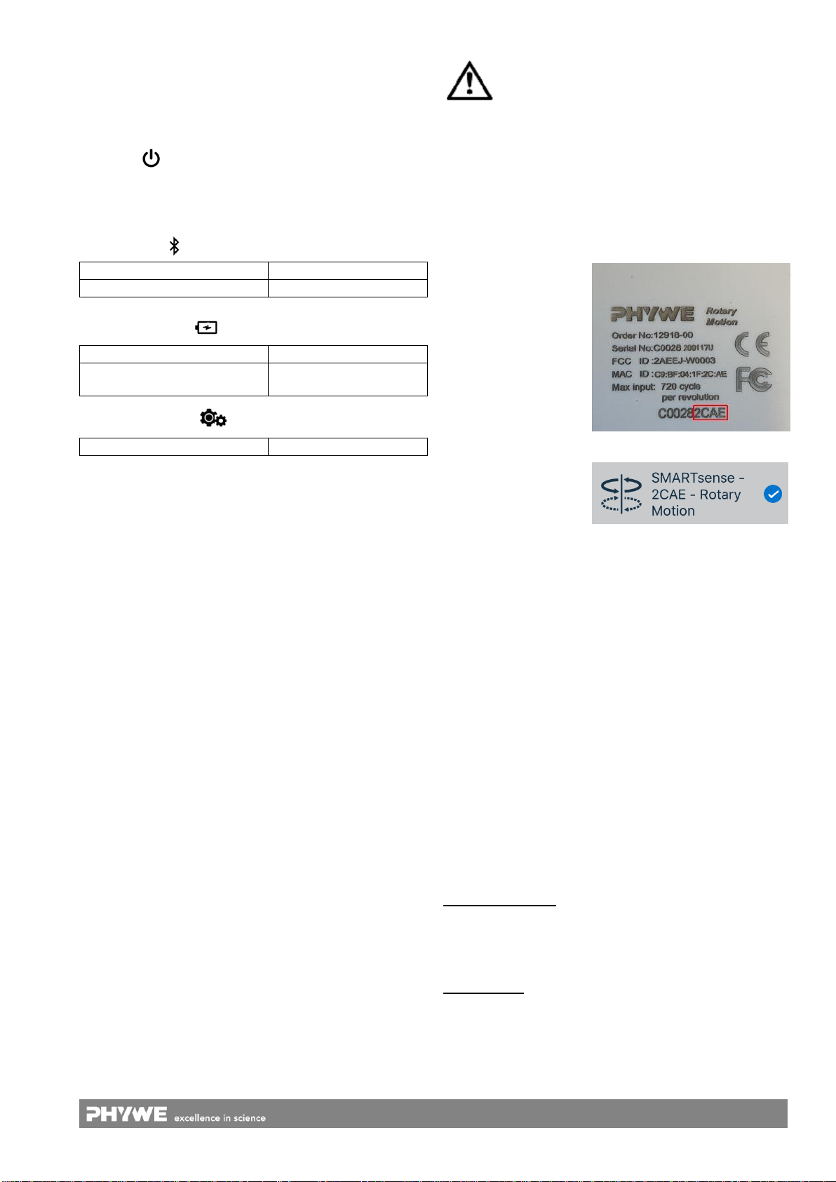
There is a 9-digit code
on the back of the sen-
sor (Fig.2). The last 4
digits of the code are
displayed as the sensor
name in the software
(Fig.3). This enables
the precise assignment
of the sensors within
the software.
Fig. 2
Fig. 3
Selection of the sensor via the Bluetooth interface
Make sure that the Bluetooth interface is activated on the
terminal device (PC/Tablet/Smartphone) and that the soft-
ware is allowed to access the interface.
After the sensor has been selected in the software, the LED
flashes green to indicate that the connection has been estab-
lished correctly. After the sensor has been coupled with the
software, the sensor is no longer visible to other users in the
software, and therefore can no longer be selected.
If the sensor is switched on and not connected, it switches off
automatically after 5 minutes.
Selection of the sensor via the USB interface
For this purpose the sensor must be plugged into the USB
port of the end device. It is not necessary to switch on the
sensor. The sensor is automatically recognized and dis-
played. It can be selected and connected directly.
5.3 Recording of measurement data
Measuring principle:
An incremental encoder determines the current rotational po-
sition. When a measurement is started, the velocity and ac-
celeration are calculated from the rotational position over a
time interval.
Measurement:
Start recording at Software. The position is set to 0 and the
measured values are transmitted at a fixed time interval. Dur-
ing the measurement the Bluetooth LED lights up permanent-
ly.


