ched to the start of the track (the end with the pressure tube
connection), unless the mechanical starting system
(11202.13 + 11202.14) (not included in 11202.77) is used.
In this case it is fitted instead of the end-holder.
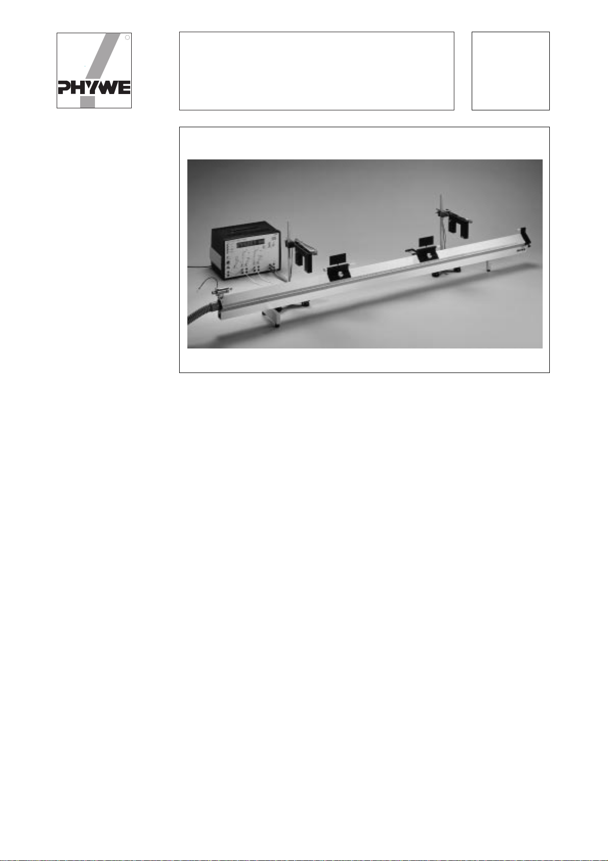
The air track rail is set up on a flat surface that is as level as
possible and connected to the blower using the pressure
tube. The blower pressure should be set such that the gli-
ders just reliably elevate from the track and are freely sup-
ported on the air cushion; depending on the glider load this
can be at different pressures. A blower pressure that is too
high should be avoided, because it impairs the steady po-
sitioning of the glider.
The track, which itself has been adjusted at the works, must
be aligned as level as possible with the two adjustment scr-
ews on the base of the carrier rail. This can be initially car-
ried out by eye or using a spirit level; accurate alignment
must be obtained with the blower operating and by setting
a glider on the track. With a properly levelled track there
should be no or very little glider acceleration ; a slight pen-
dulum movement caused by the air current is unavoidable.
This test should be conducted on various points on the
track. The action of external forces, e.g. due to vibration or
draughts should be avoided.
3.2 Electronic timing
The electronic digital counters mentioned in the list of
equipment are suitable for the time measurement. One or
two light barriers can be connected to these devices for el-
ectro-optical control. The light barriers must be arranged at
the required point on the track so that the screen on the gli-
der interrupts the beam of light between the light source and
the photoelectric sensor when it passes. A holder made
from stand-support components is suitable. A ruler with gli-
ders can be attached to the holding structure to demon-
strate the length measurement.
3.3 Producing constant acceleration
The glider should be fitted with the Hook (11202.07*). To
produce the acceleration, a Silk Thread (02412.00*) to the
end of which a Weight Holder (02407.00*) is attached, is
passed over a low-friction Precision Pulley (11201.02*).
One or more 1g Slotted Weights (03916.00*) are placed on
the holder; up to 20g is permissible for the pulley.
Since the nominal mass of the glider (200g for the glider
with 100mm screen and two plug-in elements) is subject to
a certain tolerance, weighing should be carried out to exac-
tly determine the accelerated mass and supplementary
weights used if required. Also, the mass of the weight hol-
der (1g) and the 1g slotted weights used must be taken into
account as an additional corrective quantity; an equivalent
mass for the rotating pulley can be taken as 2.2g.
* not included in 11202.77.
3.4 Readjusting the air track rail
A feature of the Air Track Rail 11202.17 is that it can be re-
adjusted with regard to the straightness of its longitudinal
profile. Correction of the basic ex-works adjustment is ho-
wever only necessary it the straightness has become im-
paired due to mechanical stressing of the track.
The adjustment procedure demands a certain amount of
manual skill as well as a systematic method of working and
assuming this, it can be carried out by the user. Seven Allen
screws accessible on the bottom of the carrier rail are to be
adjusted where required. A normal Allen key, 5mm AF, is
needed to adjust these M6 screws (pitch 1mm/turn). Gene-
rally for readjustment, an adjustment of only up to one half
turn of the screw is required which must be taken in stages
and the track straightness should be tested at each stage.
By turning the screw clockwise the square tube is pulled do-
wnwards in the vicinity of the screw and it is raised when the
screw is turned in the opposite direction.
The longitudinal straightness of the track section should at
least be determined qualitatively before the adjusting scr-
ews are adjusted. This is done with the blower operating
and with the aid of a glider put on the air track rail. First the
track should be aligned with it level at the centre. Then the
glider is positioned at various points along the track and the
direction and approximate magnitude of the acceleration
occurring at that point is found. (If an estimate is not regar-
ded as being sufficient, the time t for the glider to move from
its starting point over a distance s can be determined. The
acceleration is then a = 2 s/t2). The magnitude is a measure
of the gradient of the track at the test point.
It is essential that external force affects, such as draughts,
are avoided during the test.
The qualitative straightness of the track can be found from
the results and, as an aid, can be drawn out. It may be, for
example, that a maximum or a minimum is present in the
central track section. Then the adjustment screws are ad-
justed at the point of the extreme misalignment and the sur-
rounding vicinity according to the determined misalign-
ment. As mentioned above, this should be carried out in
small steps. Finally, the straightness of the track should be
tested along the whole track. If the misalignment exhibits a
number of extreme points, then an analogous procedure
should be followed for their correction.
4 EXPERIMENT LITERATURE
Versuchseinheiten Physik,
Lineare Bewegungen 16001.01
Physik in Demonstrationsversuchen,
Ausgabe A/B, Band Mechanik 01141.21
Physik in Demonstrationsversuchen,
Ausgabe C, Teil 1 01146.01
University Practicals in Physics 00067.72
Manual for COMEX Air Track Rail 01171.02
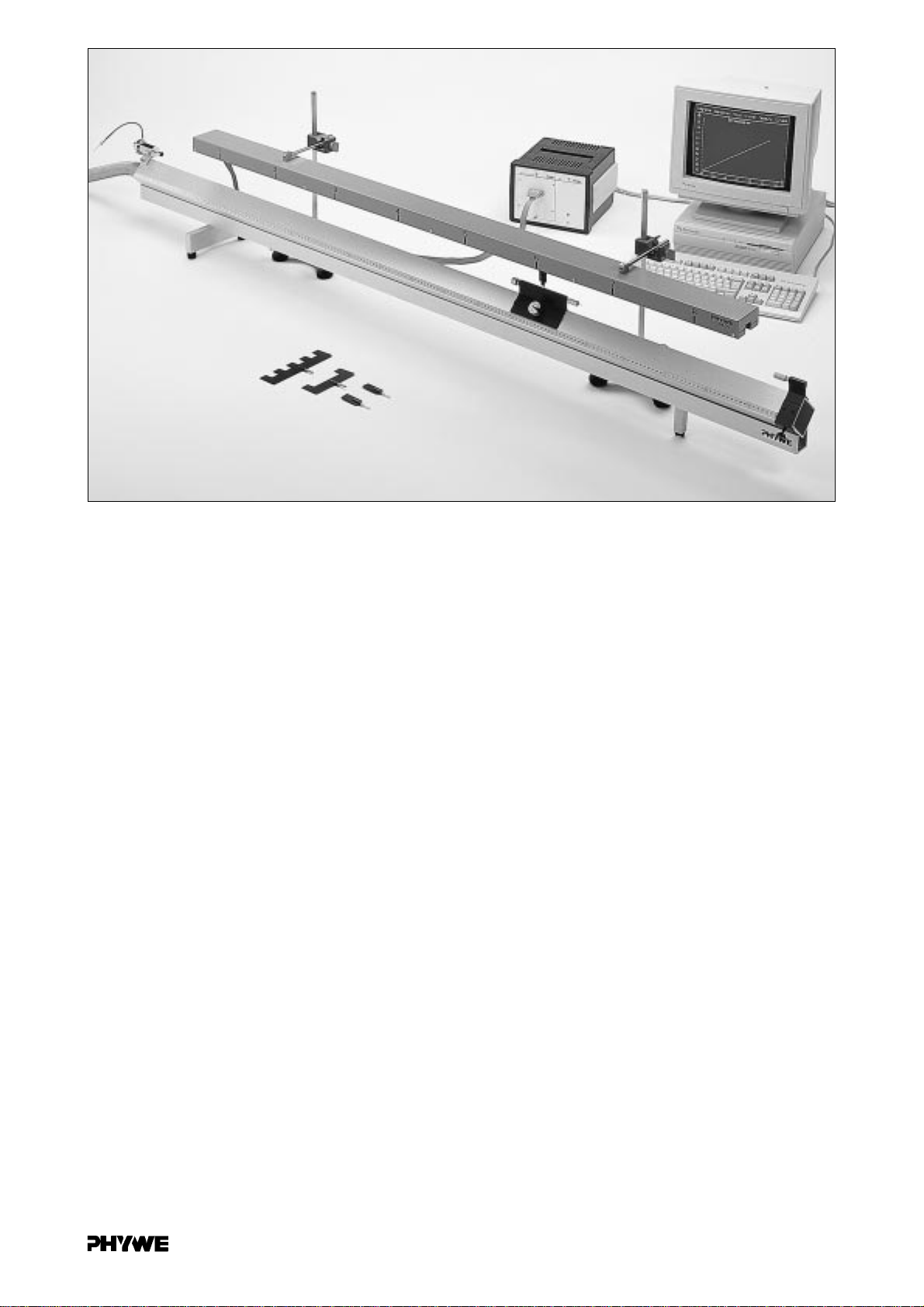
Computer-Aided Measurement Acquisition and Evaluation
of Air Track Rail Experiments with the COMEX Interface Sy-
stem
311202.17