manuals.online logo
Brands
  1. Home
  2. •
  3. Brands
  4. •
  5. PHYWE
  6. •
  7. Laboratory Equipment
  8. •
  9. PHYWE Cobra SMARTsense Dual Photogate User manual

PHYWE Cobra SMARTsense Dual Photogate User manual

1
www.phywe.com, © All rights reserved 12945-00 / 2821
Operating
instructions
Cobra SMARTsense Dual Photogate
12945-00
12945-01
PHYWE Systeme GmbH & Co. KG
Robert-Bosch-Breite 10
D–37079 Göttingen
Telefon +49 (0) 551 604–0
Fax +49 (0) 551 604–107
E-mail [email protected]
Internet www.phywe.com
The unit complies
with the applicable
EC-guidelines
Fig. 1: 12945-00 Cobra SMARTsense Dual Photogate
TABLE OF CONTENTS
1SAFETY PRECAUTIONS
2PURPOSE AND CHARACTERISTICS
3FUNCTIONAL AND OPERATING ELEMENTS
4NOTES ON OPERATION
5 HANDLING
6TECHNICAL DATA
7SCOPE OF DELIVERY
8ACCESSORIES
9 CONFORMITY
10 DISPOSAL
1 SAFETY PRECAUTIONS
Carefully read these operating instructions completely
before operating this instrument. This is necessary to
avoid damage to it, as well as for user-safety.
Only use the instrument for the purpose for which it was
designed.
Only use the instrument in dry rooms in which there is no
risk of explosion.
Protect the instrument from dust, moisture and vapours.
Use a slightly moist lint-free cloth to clean the instrument.
Do not use aggressive cleaning agents or solvents.
Take care that no liquid penetrates in through the hous-
ing openings, as such penetration would result in dam-
age to Sensor.
Do not open the unit.
2 PURPOSE AND CHARACTERISTICS
The sensor is used to measure kinematic physical quantities
such as time, movement, speed and acceleration. The
measured values are transmitted via Bluetooth or USB to any
end devices such as tablets, smartphones etc.
Caution!
2
www.phywe.com, © All rights reserved 12945-00 / 2821
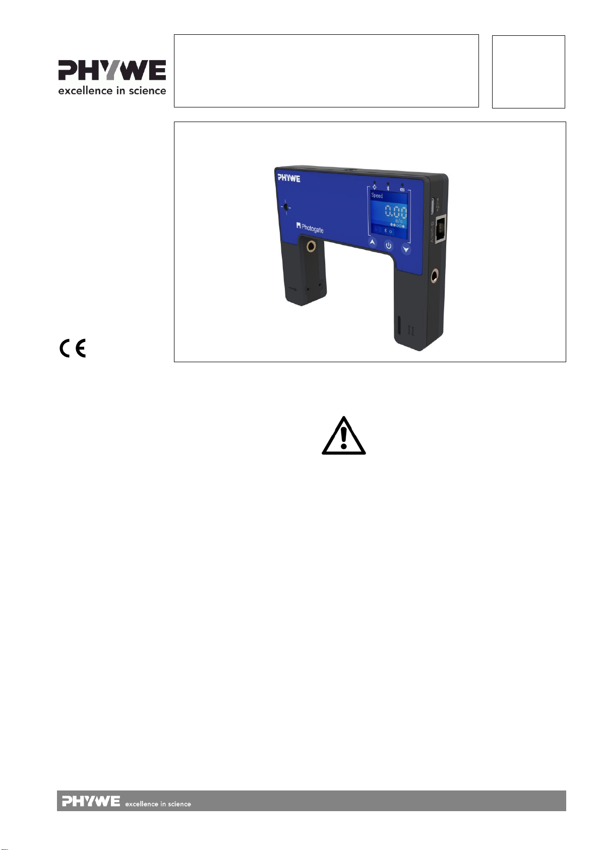
3 FUNCTIONAL AND OPERATING ELEMENTS
3.1 Operating elements
The sensor has a power button, two arrow keys for naviga-
tion and 3 LEDs whose function is described below.
Function of the power button
Short press
Confirmation at navigation
Long press (>1s)
Switch device on/off
Function of the up-button
Call up the menu, navigate up
Function of the down-button
Call up the menu, navigate down
Laser detection LED
Illuminated red
No Laser signal detected
Off
Laser signal detected
Bluetooth-LED
Flashing red every 2 seconds
Not connected
Flashing green every 2 seconds
Connected to the ter-
minal device
Flashing green every 4 seconds
Running measurement
Battery charge LED
Flashing red every 2 seconds
Low battery
Illuminated red
Active charging process
Illuminated green
Charging process
completed
3.2 Functional elements
Fig. 2
3.3 USB port
The battery, which is permanently installed in the sensor, is
charged via the type C USB port. Furthermore, communica-
tion with a computer takes place via this interface
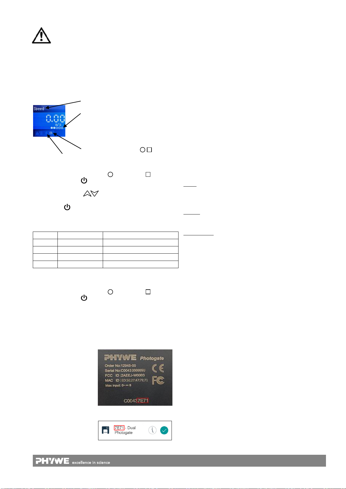
3.4 Connection interface
2 Photogates can be connected together. Use the supplied
RJ-45 cable for the connection. After plugging in the cable
and switching on a device, you will be asked to specify which
device is "A" and which device is "B". The confirmation is
made by briefly pressing the power button .
3.5 Laser receiver
If a laser pointer is aligned with the receiver, the laser detec-
tion LED (see 3.1) will signal this. An interruption of the laser
beam is now detected and evaluated accordingly by the de-
vice. (see modes in chapter 5.2)
3.6 Gittereingang
Here the grating can be
threaded in. With the help
of the grating, continuous
data acquisition can be
carried out, e.g. for drop
tests.
Fig.3
3.7 Incremental wheel base (only in 12945-01)
Fit the base to the housing of the photogate using the screw
provided (Fig.4) and then push the incremental wheel onto
the base until a click is heard (Fig.5).
Fig.4 Fig.5
4 NOTES ON OPERATION
This device fulfils all of the technical requirements that are
compiled in current EC guidelines. The characteristics of this
product qualify it for the CE mark.
This instrument is only to be put into operation under special-
ist supervision in a controlled electromagnetic environment in
research, educational and training facilities (schools, universi-
ties, institutes and laboratories).
The individual connecting leads are each not to be longer
than 2 m.
The instrument can be so influenced by electrostatic charges
and other electromagnetic phenomena (HF, bursts, indirect
lightning discharges) that it no longer works within the given
specifications. Carry out the following measures to reduce or
eliminate the effect of such disturbance: Ensure potential
equalization at the PC (especially with Laptops). Use screen-
ing. When a total failure of the instrument occurs, unplug it
and plug it back in again for a reset.
5 HANDLING
This section describes the start-up of the sensor and the re-
cording of measurement data. Please read this section thor-
oughly in order to avoid failures or operating errors.
5.1 Charging process
Use a USB-C cable to connect the sensor to a computer or
USB charger (not included).
During the charging process, the battery charge LED lights
up red. When the charging process is complete, the battery
charge LED lights up green. The charging time for a com-
pletely discharged battery is 3 hours maximum.
Laser
Detector
USB
A-B
Connection
Grating entrance
Incremental wheel socket
Successful
Connection
Devices-
definition
3
www.phywe.com, © All rights reserved 12945-00 / 2821
Disconnect the charger at the latest four hours af-
ter the completion of the charging process. Other-
wise, the service life of the battery may be nega-
tively affected.
5.2 Start-up
Use without software / App
Switch on the sensor by pressing and holding the power but-
ton for more than 3s. The start screen is now displayed.
A measurement can be started ( ) or stopped ( ) by press-
ing the power button .
Press the arrow keys to access the selection of modes
or settings. The modes are also confirmed by pressing the
power button .
The following modes can be selected:
Mode 1
Speed
Dual Photogate
Mode 2
Counter
Dual Photogate / Laser
Mode 3
Acceleration
2x Dual Photogate
Mode 4
Distance
Grating
Mode 5
Shading time
Dual Photogate / Laser
Measured value recording
A measurement can be started ( ) or stopped ( ) by press-
ing the power button .
Use with software / App
Switch the sensor on by pressing the on-button for more than
3 seconds. The Bluetooth LED lights up red. Start the
measureApp application and select the sensor.
A 9-digit code is printed
on the back of the sensor
(Fig.6). The last 4 digits
of the code are displayed
as sensor designation in
the software (Fig.7). This
enables an exact
assignment of the
sensors with the
software.
Fig. 6
Fig. 7
Selection of the sensor via the Bluetooth interface
Make sure that the Bluetooth interface is activated on the
terminal device (PC/Tablet/Smartphone) and that the soft-
ware is allowed to access the interface.
After the sensor has been selected in the software, the LED
flashes green to indicate that the connection has been estab-
lished correctly. After the sensor has been coupled with the
software, the sensor is no longer visible to other users in the
software, and therefore can no longer be selected.
If the sensor is switched on and not connected, it switches off
automatically after 5 minutes.
Selection of the sensor via the USB interface
For this purpose the sensor must be plugged into the USB
port of the end device. It is not necessary to switch on the
sensor. The sensor is automatically recognized and dis-
played. It can be selected and connected directly.
6 TECHNICAL DATA
Operating temperature range: 5 - 40°C
Rel. humidity < 80%
Time:
Range
Resolution
Accuracy
Speed:
Range
Resolution
Acceleration:
Range
Resolution
0…∞ s
1 µs
± 10 µs
± 100 m/s
0,01 m/s
± 100 m/s2
0,01 m/s2
Max. date rate
Battery capacity
Max. wireless range (open field)
100 Hz
250 mAh
30 m
Dimensions (length x width x height)
130 x 105 x 26 mm
Weight
165 g
7 SCOPE OF DELIVERY
The scope of delivery 12945-00 includes:
Cobra SMARTsense Dual Photogate 12945-00
USB-connecting cable type C
RJ-45 connecting cable
2x Grating
Threaded rod (length 10cm)
Operating instructions
The scope of delivery 12945-01 includes:
2x knurled screw
2x mounting brackets for track mounting
Incremental Base socket (clamping socket)
Incremental wheel
Operating instructions
Measuring mode
Available light barriers
From left to right:
Device A gate 1, gate 2
Device B gate 1, gate 2
Laser receiver
Bluetooth connection
Measurement start/stop ( )
4
www.phywe.com, © All rights reserved 12945-00 / 2821
8 ACCESSORIES
The following accessories are available:
Cobra SMARTlink 12999-99
USB charger 07934-99
USB-connecting cable type C 07922-15
USB-Bluetooth-Adapter 07936-00
Grating (10 pieces) 12945-02
Software measureLAB 14580-61
Free measureApp available from supplier portals
iOS
Android
Windows
9 CONFORMITY
10 DISPOSAL
The packaging mainly consists of environmentally-friendly
materials that should be returned to the local recycling sta-
tions.
PHYWE Systeme GmbH & Co. KG
Abteilung Kundendienst
Robert-Bosch-Breite 10
D–37079 Göttingen
Telefon +49 (0) 551 604-274
Fax +49 (0) 551 604-246
Do not dispose of this product with normal
household waste. If this unit needs to be
disposed of, please return it to the address
that is stated below for proper disposal
PHYWE Systeme GmbH & Co.KG hereby
declares that the radio system type 12945-
00 complies with the 2014/53/EU directive.
The complete text of the EC Declaration of
Conformity is available at the following In-
ternet address:
www.phywe.com/en/ec-declaration

This manual suits for next models

2

Other PHYWE Laboratory Equipment manuals

PHYWE Air Track Rail 11202.17 User manual

PHYWE

PHYWE Air Track Rail 11202.17 User manual

PHYWE Cobra SMARTexperiment User manual

PHYWE

PHYWE Cobra SMARTexperiment User manual

PHYWE 11207-30 User manual

PHYWE

PHYWE 11207-30 User manual

PHYWE PJ45 User manual

PHYWE

PHYWE PJ45 User manual

Popular Laboratory Equipment manuals by other brands

Buchi 535 manual

Buchi

Buchi 535 manual

VWR AccuSterilizer 1130 Series Operation manual

VWR

VWR AccuSterilizer 1130 Series Operation manual

Hamilton DIGITAL MEDIA LAB quick start guide

Hamilton

Hamilton DIGITAL MEDIA LAB quick start guide

Miele A 306/1 operating instructions

Miele

Miele A 306/1 operating instructions

Sihon SH0004P installation instructions

Sihon

Sihon SH0004P installation instructions

Thermo Scientific 3960 Operating and maintenance manual

Thermo Scientific

Thermo Scientific 3960 Operating and maintenance manual

Fritsch PULVERISETTE 1 classic line operating instructions

Fritsch

Fritsch PULVERISETTE 1 classic line operating instructions

ibidi Heating System instructions

ibidi

ibidi Heating System instructions

Knauer Azura Assistant ASM 2.1L user manual

Knauer

Knauer Azura Assistant ASM 2.1L user manual

NUVE ST 30 user manual

NUVE

NUVE ST 30 user manual

Labnet ProBlot 6 instruction manual

Labnet

Labnet ProBlot 6 instruction manual

NSK Ultimate XL Operation manual

NSK

NSK Ultimate XL Operation manual

SHP Laboklav 55 user manual

SHP

SHP Laboklav 55 user manual

Agilent Technologies Labware MiniHub G5584A user guide

Agilent Technologies

Agilent Technologies Labware MiniHub G5584A user guide

Sartorius Proline Plus user manual

Sartorius

Sartorius Proline Plus user manual

Norecs HumiStat manual

Norecs

Norecs HumiStat manual

Bertin Technologies PRECELLYS 24 user manual

Bertin Technologies

Bertin Technologies PRECELLYS 24 user manual

Centurion Scientific Pro-Research instruction manual

Centurion Scientific

Centurion Scientific Pro-Research instruction manual

manuals.online logo
manuals.online logoBrands
  • About & Mission
  • Contact us
  • Privacy Policy
  • Terms and Conditions

Copyright 2025 Manuals.Online. All Rights Reserved.