PIAB C Series User manual

VACUUM CONVEYING
C Series Conveyor
Troubleshooting Guide
www.piab.com

VACUUM CONVEYORS
2
INTRODUCTION
Thank you for your purchase of a
PIAB Vacuum Conveyor.
This manual provides you all the information
necessary for the successful installation, op-
eration and maintenance of your unit. We
strongly recommend that this manual be
carefully studied prior to installation or opera-
tion. Doing so will avoid the possibility of in-
advertent damage or malfunction of the
equipment. Following the recommended
maintenance instructions will ensure better
performance and extended equipment life.
Also included within this manual is a list of
recommended spares. These items are sub-
ject to wear during normal use. We recom-
mend that they be purchased in advance and
keptinstocktoavoid possible down time and
future delays.
Because PIAB equipment may be shipped as
part of an installation involving other types of
equipment, or dissimilar units are sometimes
connected to perform specific functions, you
should familiarize yourself with the manuals
covering the other equipment before pro-
ceeding with installation. By cross-referenc-
ing the manuals, you may save valuable in-
stallation time and avoid improper operation.
In the design and manufacture of this equip-
ment, PIAB has exercised the utmost care to
ensure many years of trouble-free operation.
Intheeventthatpartsortechnicalassistance
is required, please contact us at:
PIAB USA, Inc.
65 Sharp Street
Hingham, MA 02043
Ph: (800) 321-7422/ (781) 337-7309
Fax: (781) 337-6864
www.piab.com
It is the users' responsibility to operate this
equipmentina safe mannerandensurecom-
pliance with all applicable safety laws and
codes.
WARRANTY:
PIAB Vacuum Conveyors are thoroughly in-
spected and tested before shipping. Each
PIAB Vacuum Conveyor is warranted to be
free of defects in workmanship and materials
forfiveyears fromdateof purchase(filterand
wear parts excluded.)

VACUUM CONVEYORS
3
CONTENTS
Page
SAFETY INSTRUCTIONS 4
CONNECTION EXAMPLES 7
CU-1A/B Connection
CU-2A/B Connection
PPT/R Connection
VCC-EP Connection
ACHIEVING THE DESIRED RATE 16
Filter replacement
Cleaning and Maintaining the Pump
MLL200-1200 Components
MLL Panel Component
Inside Components of MLL Pumps
MLD100 Components
TROUBLESHOOTING GENERAL 24
TROUBLESHOOTING L SERIES PUMP 25
TROUBLESHOOTING CU-1A/B 33
PIAB Control Unit CU-1A/B & CU-2A/B
CU control function and pneumatic diagrams
/ Pipe emptying
TROUBLESHOOTING PPT/R 42
PIAB Control Unit PPT/R
PPT/R control function and pneumatic
diagram, connections
Disassembling a PPT/R control
TROUBLESHOOTING VCC-EP 48
PIAB Control Unit VCC-EP
Mounting and connections
Valve Connections for the VCC-EP
TROUBLESHOOTING WITH
A LEVEL DETECTOR 51
PIAB Level Detector
TROUBLESHOOTING INJECTION VALVES 51
Pneumatic Injection Valve
CLEANING OUT A PACKED CONVEYOR 54
Air Shock Assembly
MAINTENANCE SCHEDULE 55

VACUUM CONVEYORS
4
SAFETY INSTRUCTION
Instructions for building into a system
PIAB vacuum conveyors are CE marked. The person
who installs the conveyor in another main system has
the responsibility of carrying out a risk analysis when
this is desired.
Dust explosions
When handling and conveying dry powders and mate-
rial consisting of small particles, there is a risk that a
dust explosion may occur. A dust explosion may occur
whencertainfinelydivided materialsare mixedwith air
(oxygen) and then are ignited by, for example, a spark.
In order to minimise the risk of dust explosions, all in-
cludedpartsoftheconveying systemmustbe connect-
ed to one and the same point of earth (equipotential)
accordingto applicableregulations.Itisalsoimportant
not to smoke, weld or carry out other work where the
risk of generation of sparks may be present in the vi-
cinity of the conveyor.
Inthetablebelowaresomeexamplesofmaterialsthat
may cause dust explosions.
The conveyor may not be used in explosive surround-
ings containing the following gases: acetylene, carbon
disulphide, hydrogen, hydrogen sulphide and ethylene
oxide.
ATEX-Atmosphere Explosible and CE.
PIAB vacuum conveyors are not EX classified.
PIAB vacuum conveyors conforms to EU directive 94/
9/EC.
Cleaning of filters
Itisimportant tocheckand clean/changefiltersatreg-
ular intervals so that they are not clogged, as this
might lead to the fact that the filters will be subjected
to overload, and that undesired matters or particles
leak from the conveyor.
Emergency stop
The system builder shall provide the machine with an
emergency stop function. As an option to the vacuum
conveyor there is a remote control box with a built-in
emergency stop function.
Start/stop of the conveyor
Theconveyorisstartedeitherwiththeprovided control
unit or via another main control system. The conveyor
stops if the supply of compressed air is suddenly inter-
rupted. The conveyor must be re-started by the opera-
tor even if the supply of compressed air is reactivated.
Vacuum power at the inlet
Careless usage and incorrect installation of the feed-
ing point of the vacuum system may cause injuries.
The vacuum level is concentrated at the feeding point
and may cause injuries to eyes and mucous mem-
branes.
XNeveraimasuctiontube,a feednozzleor a hose
at anyone.
XThe larger the suction inlet, the higher the power
and danger.
XThe installation must be made so that the inlet
cannot contact the operator and other people.
XAlways remember to disconnect the supply of
compressed air when cleaning or servicing the
vacuum conveyor.
X
Aluminium Carbon
Aspirin Magnesium
Cotton Flour
Iron Nylon
Cacao Sugar
Coffee Corn
Cork Wood
+O2+=

VACUUM CONVEYORS
5
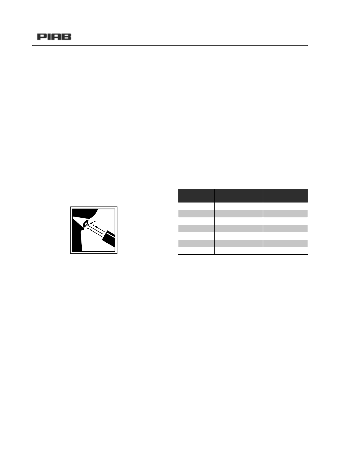
Exhaust from the vacuum pump
The exhaust air from the conveyor’s vacuum pump
may, in certain applications, constitute a risk and
cause injuries. If the filter is not fully intact when pow-
der with small particles is conveyed, the particles may
penetratethefilterand enter the pump, andfurtheron
out to the atmosphere and possibly contaminate it.
Dangerous gases may also be generated and be car-
ried out together with the exhaust air. In such cases
the pump shall be fitted with a central exhaust with an
external filter. In certain cases, another alternative
could be the use of a sterile-filter unit. Never look di-
rectly into the outlet of the vacuum pump. Do not for-
get to disconnect the supply of compressed air when
cleaning or servicing the vacuum conveyor
Compressed air
We recommend that compressed air of at least quality
class 3 is used (ISO norm 8573.1) for PIAB’s vacuum
pumps. This means that only a maximum of 5 mg/m3
of a maximum of 5 µ size particles may be present in
the compressed air.
For the USDA conveyor to conform to the American re-
quirements of the authorities, the air for the air shock
must be delivered according to 3-A Accepted Practice
No. 604-04. This means, among other things, that the
air shall be free from oil and be filtered.
Preventing pressure-drops in
the air supply
It is important to correctly dimension the compressed-
air hose that supplies the conveyor so that unneces-
sary pressure drops do not occur. The longer the hose,
the larger the dimension required. Also remember
thatpush-inconnections with built-innon-returnvalves
may cause pressure drops. Also, take into consider-
ation that there may be other devices in the com-
pressed-air network that might consume compressed
air.
Dimensioning of the compressed-air pipeline
A very important part of a vacuum system is correctly
dimensioned hoses and connections. In order to get
the highest possible performance from each vacuum
pump, the table below that recommends hose diame-
ters in mm (inner diameter) should be used.
The above compressed-air connections apply for pipe-
lines that are shorter than 10 m (33 ft). If the pipeline
is longer than 10 m (33 ft), select a pipeline of a larger
diameter.
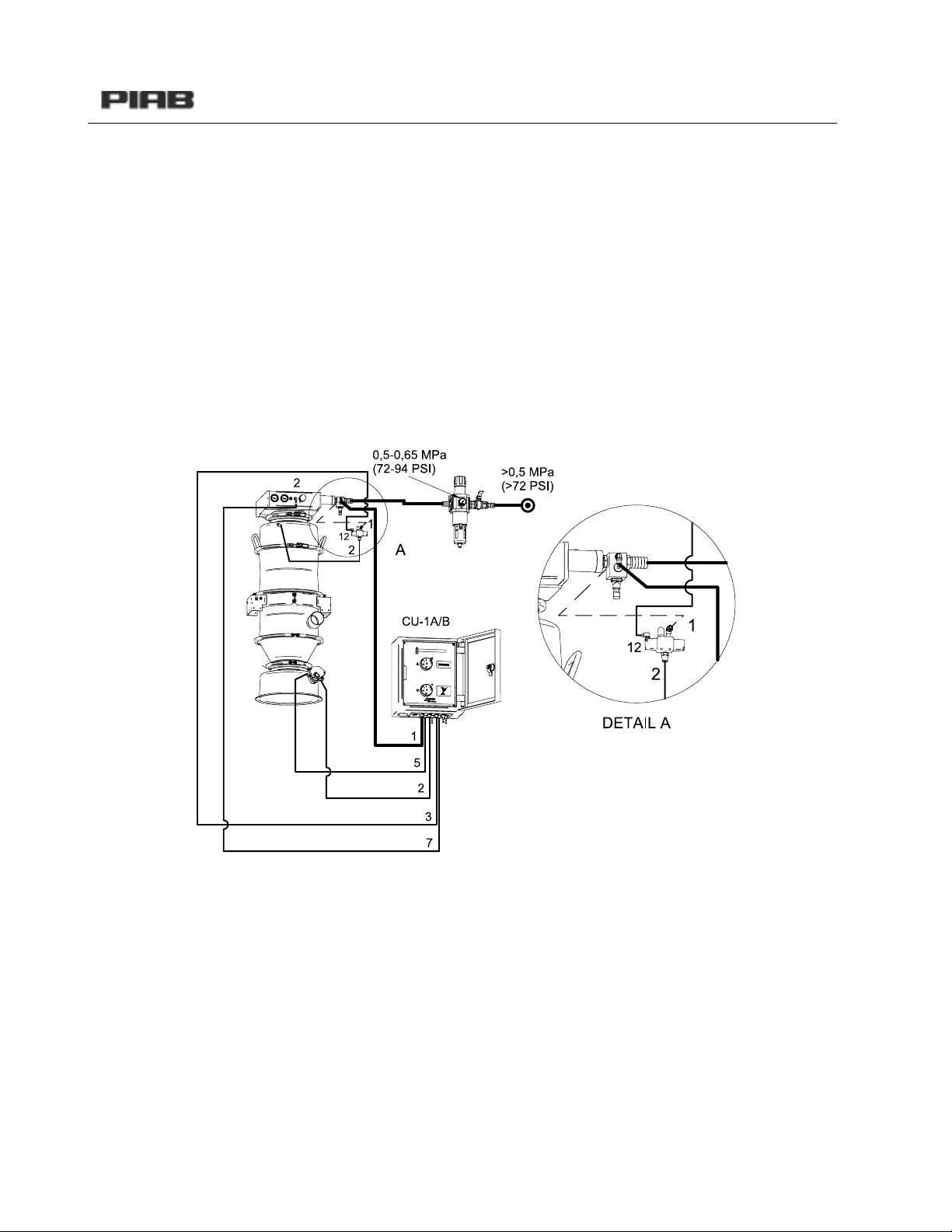
Installation of compressed air
The feed pressure of the compressed air is between
0.4(58)and0.6 (87 psi) MPaforPIABvacuum convey-
orsandpumps.Careless usage ofcompressedairmay
cause injuries.
The compressed air may not be used for any other pur-
pose than specified.
All applicable safety regulations for installation, opera-
tion and maintenance must be followed.
Always disconnect the supply of compressed air when
cleaning or servicing the vacuum conveyor.
You are responsible for your own and other people’s
safety at the place of work.
Contact your local PIAB distributor if you have any
questions.
Pump model Compressed-air
connection
Exhaust connec-
tion (mm)
Maxi L100 1/2" 75
Maxi L200 1/2" 75
Maxi L400 1/2" 75
Maxi L600 1" 2x75
Maxi L800 1" 2x75
Maxi L1200 1" 2x75
Maxi L1600 1" 2x75

VACUUM CONVEYORS
6
Disconnecting the compressed-air pipeline
Before the compressed-air pipe of the pump is discon-
nectedthepressuretothecompressor mustbeturned
off. After that, the pipeline may be disconnected.
Dismounting the conveyor
It important that the conveyor is emptied of its powder
before dismounting is started. The compressed-air
supply must be disconnected before dismounting the
conveyor.
Mounting of the conveyor
The conveyor is delivered mounted. When mounting it
after cleaning/servicing, it is important that seals and
filters are mounted correctly so that leakage does not
occur. C21 and C33 shall be anchored at one point at
least (either at the bottom valve unit or at the connec-
tion girdle). C56 shall be anchored at two points at
least (at the bottom valve unit and at the upper or low-
er connection bracket).
Hot surfaces
There is a risk that the external air shock becomes hot
(60° C, 140° F) during and after use.
Position of the operator
The operator shall be at a position where he can easily
start and stop the conveyor.
Remote control of the conveyor
When using remote control, the system builder should
ensure that the conveyor can not be simultaneously
operated from two locations.
Installation of the conveying pipeline
Correctdimensioning andinstallation isAandOforthe
system to work in the best possible way.
Please contact your local PIAB distributor as to dimen-
sioning of the diameters of the pipes, their length,
number of bends and possible option of injection units
or pipe emptying function. It is important that the pipe-
line system is sealed in order to prevent the conveyed
powder from leaking from the equipment to cause
damage to other devices and injuries. It is also impor-
tanttomakesurethatno foreignmatterscaninadvert-
ently be sucked into the conveyor.
Some basic tips
XThe conveying pipeline should be installed without
having any unnecessary bends.
XAvoid inclined rises in the conveying pipeline.
XThe radius of the pipeline should be at least 10
times the pipe diameter.
XChoose pipes instead of hoses where possible.
XAvoid all types of edges and restrictions at pipe
joints and connections.
Noise level
The measured noise levels (72–76 dBa) have been
measured in the following manner. The distance be-
tween the pump and sound level meter = 1 metre. The
higher measuring value applies to the exhaust air-flow
in the direction of the sound level meter and the lower
measuring value applies to the exhaust air flowing
from the sound level meter. Please notice that the
noise level of the conveying depends on the kind of
powder that is conveyed.

VACUUM CONVEYORS
7
CONNECTION EXAMPLES
CONTROL UNIT CU-1A/B ART. NO. 01 04 550
ART. NO. 01 04 552

VACUUM CONVEYORS
8
CONTROL UNIT CU-1A/B WITH FLUIDISATION ART. NO. 01 04 550
ART. NO. 01 04 552

VACUUM CONVEYORS
9
CONTROL UNIT CU-1A/B WITH FLUIDISATION AND LEVEL DETECTOR ART. NO. 01 04 550
ART. NO. 01 04 552

VACUUM CONVEYORS
10
CONTROL UNIT CU-1A/B USDA ART. NO. 01 04 550
ART. NO. 01 04 552

VACUUM CONVEYORS
11
CONTROL UNIT CU-2A/B ART. NO. 01 04 540
ART. NO. 01 04 548

VACUUM CONVEYORS
12
CONTROL UNIT CU-2A/B WITH FLUIDISATION AND LEVEL DETECTOR ART. NO. 01 04 540
ART. NO. 01 04 548

VACUUM CONVEYORS
13
CONTROL UNIT CU-2A/B WITH FLUIDISATION ART. NO. 01 04 540
ART. NO. 01 04 548

VACUUM CONVEYORS
14
CONNECTION EXAMPLES

VACUUM CONVEYORS
15
VALVE UNIT VCC-EP
VALVE UNIT VCC-EP WITH FLUIDISATION

VACUUM CONVEYORS
16
ACHIEVING THE DESIRED RATE
Is the air pressure at least 87 psi entering into the pump, in the proper line size, and with enough volume?
A. If the conveyor is functioning fine but the rate needs to be changed, try adjusting the timers. Since each ma-
terial conveys in a different manner, there are not particular on and off times that will achieve certain rates. If
the material has all been dumped out and the bottom door remains open, the off time can be shortened. Try
minor adjustments, increasing the on time and decreasing the off time. The off time may need to be increased
as the on time is increased to avoid packing the material in the conveyor.
Note: The conveyor has a maximum internal volume, please consult the user manual for your specific conveyor.
B. If the product tends to move in slugs (big clumps of material that fill the line) or dense phase, increased aspi-
ration may be necessary. The easiest way to add more air is at the feed point.
1. Feed Wand - The standard feed wands include two places to adjust the aspiration. The black piece at
thetopof the wandtwistsaroundthe wand, covering oruncoveringopeningsinthe actualwand. Themore
the openings are uncovered, the more air that is allowed to enter the system. In order to rotate the black
piece; unscrew the bottom wing nut. Retighten when the desired amount of opening is uncovered.
a.The inside tube can be adjusted up or down. If the tube is all the way down, touching the cage, there
will be less aspiration and a greater amount of product picked up. If the tube is pulled out to be even
with the outer tube, there will be increased aspiration and a decreased amount of product picked up.
The tube can be adjusted by unscrewing the top wing nut.
2. Feed Adapter - The standard feed adapters include two ball valves. Both are adjustable which allow in-
creased aspiration.
a. If the material is not flowing easily into the cone on the feed adapter, the ball valve closest to the
coneshouldbeopenedupuntiltheproductfreelyflows.Thisballvalveis attachedtoapipethatshould
be extended all the way out, approximately 8.5". If the material will not even flow into the cone, some
type of aspiration or agitator may need to be added before the feed adapter. The second ball valve
should be opened more if the material is conveying in dense phase.
b. If the material is very free flowing, it may drop from the cone into the perpendicular tube and clog
the tube. If this is the case, push the ball valve attached to the inner tube in closer to the cone.
3. Injection Valve - An injection valve can be added into a system no matter which feed method is being
used. There are two types of injection valves. The first type of injection valve has a ball valve that can be
opened for increased aspiration. The second type of injection valve senses a high vacuum and allows as-
piration as needed
Conveyor Min. Compressed
Air Line
Max. Required
Volume (scfm)
C21 100 classic .25 "14.8
C21100 .5 "14.8
C series 200 .5 "29.7
C series 400 .5 "59.0
C series 600 1.0 "89.0
C series 800 1.0 "118.6
C series 1200 1.0 "178.0
C series 1600 1.0 "237.3

VACUUM CONVEYORS
17
C. If there is little to no transport of material with a low vacuum, but the conveyor is still cycling properly.
1.The seals in between the modules may be cracked and leaking.
2.There may be a loose connection somewhere with the hose.
3.There may be too much aspiration.
a. If a sensing injection valve is being used, make sure the feed pressure is between 58-87 psi. If the
feed pressure is over 87 psi, the injection valve will remain open all of the time.
4.The seals inside of the pump may be cracked or worn. Refer to page 27.
5.Does the bottom flap close? - If not please turn to the section with the proper controller.
D. If there is little to no transport of material with a high vacuum, but the conveyor is still cycling properly.
1.The filter may be clogged.
2.Aspiration may need to be added.
3.There could be a clog in the pipeline.
4.The pump may be filled with material.
E. If there is material packed into the conveyor, and it is not dumping out properly.
1.The on time may need to be decreased.
2.The off time may need to be increased.
3.The material may be too damp.
a.The product may be sticky.
b.The compressed air may be damp, adding air to the material being conveyed.
4. Fluidization may need to be added to the conveyor. If it is already part of the conveyor, it may not be
functioning properly. The material would be stuck in the cone section located at the bottom of the convey-
or.
5.The filter air shock may not be working properly.
F. If the filter air shock does not function properly, there wouldn't be a 'bump' to shake the excess material off of
the filter. This can be heard when the bottom flap door opens.
1.Check the connections, both compressed air and from the air shock to the pump.
2.Make sure there is not a kink in the tubing to the air shock.
3.If the tubing has material in it, the tubing must be cleaned out or replaced.
4.The valve on the filtershock should push in and out easily. If not, clean it off and add alittle lubrication.
5.If the air shock still won't function properly, the air shock valve may be defective.
G. If there is material coming out of the exhaust of the pump, there is a filter problem.
1.The filter may be worn and need to be replaced.
2.The filter may have been put on wrong. Please refer to diagram on page 18, 19.
3. In either case, the side plate should be removedto look inside ofthe pump. For optimum performance
there shouldnot be any materialin the pump, especially thenozzles. Pleasereferto page23for directions
on maintaining and cleaning the pump.

VACUUM CONVEYORS
18
FILTER REPALCEMENT
1
23
45

VACUUM CONVEYORS
19
678
910
11 12

VACUUM CONVEYORS
20
FILTER CLEANING
7
It may be necessary to clean the filter elements under certain circumstances, e.g. after
a change of product. In this case, you are welcome to draw on our experience! We shall
be glad to help you choose the best cleaning method.
PITEX CLEANING
HERDING SINTERED BRUSH OFF CLEANING
cleaning procedure:
1. Your filter elements have to be dismantled in order to be
cleaned.
2. Place soiled filter element into washing machine at or below 40ºC (104ºF),
with mild detergent. Or you may handwash your filters.
3. Do not machine dry your PITEX filters.
4. Place filters on wire shelf. Allow filter to air dry completely before re-installation.
3. Reinstall the d
d
ry PITEX filter elements in the filter unit.
Brush-off cleaning procedure:
1. Your filter elements have to be dismantled in order to be cleaned.
2. Stand the filter elements in a vertical a position as
possible (e.g. lean them against a wall, see the drawing).
3. No dust should be allowed to get into the filter elements
during the cleaning operation. It is recommended,
therefore, to cover up the inside of the filter (e.g. with
adhesive tape).
4. Brush off the dust with a soft brush
-Bristle length: 75mm (3”)
-Bristle diameter: 0.7mm (0.025”)
-Bristle material: Nylon or PVC
Brush off the dust from top to bottom a maximum of 2
times, applying just a little pressure
-Contact pressure: 5N (1.1 pound force)
5. Turn the filter elements and proceed in like manner for
the rear and the narrow sides.
6. Clean the head and foot zone last, taking care not to
allow any dust to get into the filter elements.
7. Reinstall the filter elements in the filter unit.
This manual suits for next models
8
Table of contents
Popular Accessories manuals by other brands

DIAsource ImmunoAssays
DIAsource ImmunoAssays ELISA PLATE SHAKER user manual

Elk
Elk ELK-319HRR200 instructions

STEINEL
STEINEL Light Sensor Dual KNX Information

Sterilize+
Sterilize+ UV Sanitizing Wand quick start guide

STEINEL
STEINEL L 115 S installation instructions

Vega
Vega VEGAPULS Air 41 operating instructions