PIAB KVG60 Series User manual

MANUAL
KVG60 Series

English
Overview.............................................................................................. 3
Work cycle details ............................................................................... 5
Installation. .......................................................................................... 8
Parts diagram...................................................................................... 9
Maintenance...................................................................................... 11
Problems/solutions............................................................................ 15
Accessories....................................................................................... 16
Technical data ................................................................................... 17
Pneumatic diagrams ......................................................................... 19
Safety instructions............................................................................. 22
Warranties ......................................................................................... 23
CONTENTS
KVG60 Series
Specications subject to change without notice
2

English
Pos. Description
A Connection G 1/8” compressed air (1a)
B Connection G 1/8” blow-off or vacuum monitoring (1b)
CInline ejector exhaust, DO NOT COVER. The aspirated air escapes from the exhaust
cover through the written Kenos
Overview
Part list single ejector version
B
A C
KVG60 Series
Specications subject to change without notice
3

English
Part list double ejector version
Pos. Description
A Connection G 1/8” compressed air (1a)
B Connection G 1/8” blow-off or vacuum monitoring (1b)
CEjector exhaust, DO NOT COVER. The aspirated air escapes from the two exhaust
slots.
Part list BL version
Pos. Description
A Vacuum supply G 3/4” connection
B
A
C
A
B
A
KVG60 Series
Specications subject to change without notice
4

English
Work cycle details
The working cycle for a KVG gripping module follows the different technologies involved:
Check valve balls version(CVL/CVM/CVH):
1. Positioning the module at the object to handle with the grip pad parallel to the grip surface.
2. Lowering of module until contact with the grip surface
3. Sequential activation of vacuum if multiple modules are present
4. Pick-up of object to handle
5. Drop-off of object with removal of vacuum and blow-off if necessary
N.B. If vacuum is activated before KVG is in contact with the workpiece, the work-
piece will not be gripped because the check valves will be closed and not allowed
the handling.
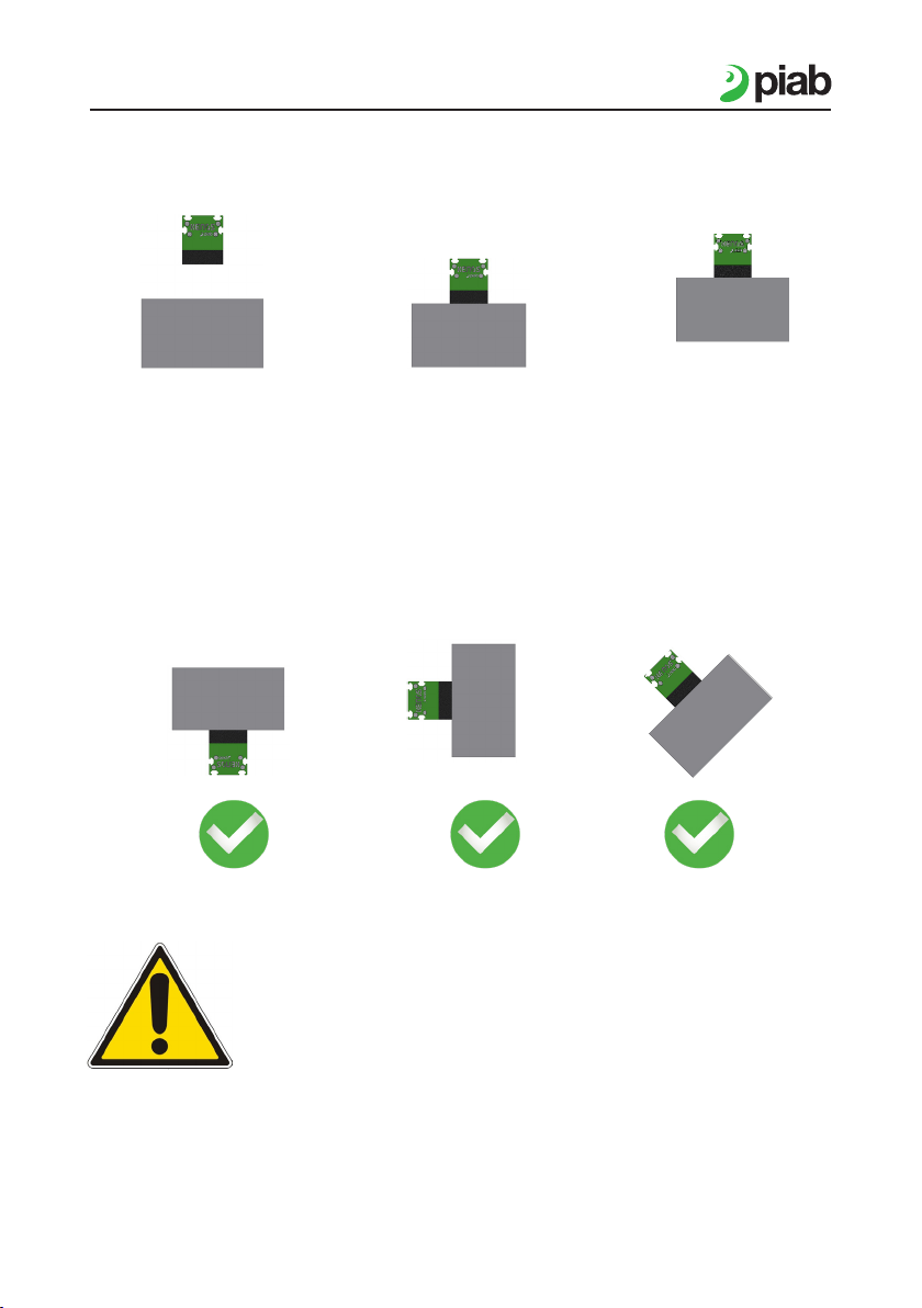
►The KVG CVL/CVM/CVH gripper module was designed for horizontal
use; turning the module upside down by 180°, or vertical grips are not
possible. Maximum tilt allowed is 45°.
►Stopping or passing through the work area of the gripper module is
prohibited, as in case of electrical or pneumatic supply failure, the
load handled by the module is released.
►The maximum vertical acceleration allowed is 5 m/s².
►Note that when check valves are present in the KVG module, the
vacuum value you can measure through a vacuum switch cannot be
used as indication for a safe grip of the object. This because we are
detecting the vacuum level inside the gripping module and, thanks to
the acting of the CV, it will be high even when the object is not present
(CV will close).
KVG60 Series
Specications subject to change without notice
5

English
Check valve piSAVE sense 02/60 (CV19):
1. Positioning the module at the object to handle with the grip pad parallel to the grip surface.
2. Lowering of module until contact with the grip surface
3. Sequential activation of vacuum if multiple modules are present
4. Pick-up of object to handle
5. Drop-off of object with removal of vacuum and blow-off if necessary
N.B. If vacuum is activated before KVG is in contact with the workpiece, the
workpiece will be gripped only if the porosity will not exceed the minimum value
(0.001 Nl/s at -45Kpa/0.0002 scfm at 13.3 -inHg) for opening each valve.
►Stopping or passing through the work area of the gripper module is
prohibited, as in case of electrical or pneumatic supply failure, the
load handled by the module is released.
►Note that when check valves are present in the KVG module, the
vacuum value you can measure through a vacuum switch cannot be
used as indication for a safe grip of the object. This because we are
detecting the vacuum level inside the gripping module and, thanks to
the acting of the CV, it will be high even when the object is not present
(CV will close).
KVG60 Series
Specications subject to change without notice
6

English
Flow reduction (FR5/FR6/FR8/FR10):
1. Positioning the module at the object to handle with the grip pad parallel to the grip
surface.
2. Lowering of module until contact with the grip surface. For fast cycle, we suggest to
activate vacuum before module is in contact with the object.
3. Pick-up of object to handle.
4. Drop-off of object with removal of vacuum and blow-off if necessary.
N.B. In this case the activation for vacuum can be done before or after contact with
the workpiece.
►Stopping or passing through the work area of the gripper module is
prohibited, as in case of electrical or pneumatic supply failure, the
load handled by the module is released.
►With the ow reduction technology, the vacuum value in the gripper
is inuenced by the degree of coverage of the gripper. The higher
degree of coverage, the higher ow is the vacuum level measured.
So in this case the vacuum switch can be used to check the grip.
Note: We recommend always running preliminary tests with original samples. We
are able to perform these tests for you.
KVG60 Series
Specications subject to change without notice
7

English
Installation
Mounting on the handling system
The gripping system is secured with the aid of slot nuts. Special slots for these nuts are
available in the basic body. The gripper can be mounted either directly, via robot ange or
via spring mountings. Information about the slots are present in the section dedicated to the
accessories.
Pos. Description
A T-slot nut
A
KVG60 Series
Specications subject to change without notice
8

English
Pos. Description
A Basic body
B Supply cover
C Supply cover seal
D COAX® cartridge
E Check valves module
F Silencer
G Exhaust cover seal
H Exhaust cover
I Cover screws
L Technical foam
Parts diagram
1. Basic body is an extruded aluminum
section and is available in different
lengths.
2. Supply/exhaust cover are made of
aluminum properly nished.
3. Technical foam is made of EPDM
FOAM.
4. Push in ejector build of 1 or more
multistage COAX® cartridge ejector.
KVG60 Series
Specications subject to change without notice
9

English
Ejector body
Pos. Description
A Cover screws
B Supply cover
C COAX®cartridge
D COAX®cartridge
E Posterior housing
F Anterior housing
G Tie-beam
H Tie-beam closing nut
I Tie-beam cover
L Supply cover seal
M O-ring
N Blind Cartridge for Midi COAX®
O Flat washer
KVG60 Series
Specications subject to change without notice
10

English
Maintenance
Ejector maintenance
For the maintenance of the push in ejector follow these steps:
►Loosen A cover screws of the supply cover and extract the complex B+C.
►Blow and clean the ejectors with compressed air. Verify that the cartridge is intact and
there are no breakages.
►Check the condition of the O-ring M, in case of damage it has to be replaced.
►Push in the complex B+C and close with A screws.
The push in ejector is modular and so it is expandable. You can, in this way, very easily in-
crease the performance. Follow these steps:
►Loosen H nuts
►Slip off posterior housing E
►Loosen the assembly tie-beam G
►Remove blind cartridge N
►Insert a new cartridge in the free housing
►Screw the assembly tie-beam to the supply cover B
►Assembly the posterior housing E
►Fix the assembly tie-beam with H nuts
More information about ejectors is present in the accessories/spare parts section.
KVG60 Series
Specications subject to change without notice
11

English
Check valves maintenance
Pos. Description
A Check valves module
B Fixing screws check valves module
C Technical foam
D Exhaust cover
E Cover screws
Maintenance
To access the check valves module, for cleaning, follow these steps with the foam upwards
to avoid the spheres spilling during operation:
►Loosen E screws and take down the cover D
►Take off technical foam C
►Loosen B screws
►Extract check valves module A
►Clean the check valves module A with compressed air.
►Follow back the same steps to assemble the gripping system.
KVG60 Series
Specications subject to change without notice
12

English
Foam maintenance
The foam that builds the gripping surface can be damaged during normal use. The average
lifetime depends on many factors: nature of the handled objects, quality of the gripping
surface, work conditions, cycle times, etc.
Foam Change
►Remove the old foam.
►Clean the aluminum prole from any
adhesive and dust residues (e.g. with
solvent).
►Attention: Check the holes are not
obstructed by any kind of residue. If
they are obstructed, clean them.
►Remove the silicon paper from the foam.
►Align the holes of the aluminum prole
with foam holes
►Fix the new foam on aluminum prole
►Attention: Prevent formation of channels,
they must be avoided.
►Press the new foam
To store the foam:
►Temperature (0 °C to 25 °C/32°F-77°F)
►Not under direct light
►Lay at
►No dust
►Free from chemicals
KVG60 Series
Specications subject to change without notice
13

English
Daily Weekly Monthly Every 6
months
Every 12
months
Check Max vacuum level of the ejector •
Check the vacuum (BL version) •
Check the check valves / FR •
Check the silencer •
Check tightenings •
Check the foam •
Check supply air pressure •
Check the electrical connection •
Check the air connection •
Check the general condition •
Clean gripper exterior •
Maintenance plan
KVG60 Series
Specications subject to change without notice
14

English
Problem Possible reason Solutions
Insufcient vacuum level
or vacuum achieved too
slowly
Operating pressure too low Increase the pressure
Internal diameter of pressure
hose too small
Use hoses with larger internal
diameter
Damaged sealing Check and replace if
necessary
Leak in pressure hose Check hoses
Dirty ejector Clean
Object not gripped
Low vacuum level See above
Insufcient suction capacity Insert one more cartridge
ejector
Dirty self-closing valves Clean
Lift is too fast
Slow down lift, avoid
acceleration peaks
(max 5 m/s²)
Pieces not suitable for lift with
this system Replace grip solution
Occluded lter Clean it
Occluded silencer Replace silencer
Foam wears very quickly The system is not corrected
placed on the workpiece
The gripping system must
be parallel to the workpiece
surface
Problems/solutions
Note: We recommend always running preventative tests with original samples. We
are available for running such tests.
KVG60 Series
Specications subject to change without notice
15

English
Accessories
T-slot nut kits:
Kit Flange:
Art. No Description
0210847 KIT-FL-FX-KVG60-50-U8
Art. No Description
0209858 T-slot nut kit 11073-M6-U8-4pcs
0209854 T-slot nut kit 11072-M5-U8-4pcs
0209851 T-slot nut kit 11071-M4-U8-4pcs
0209860 T-slot nut kit 11074-M8-U8-4pcs
KVG60 Series
Specications subject to change without notice
16

English
Technical data
Type Air consumption at 6 bar (NI/s)/ 87.0 psi (scfm)
KVG.XXX.60.XXXX.CVX.S1.XX.XX 1.75 /3.71
KVG.XXX.60.XXXX.CVX.S2.XX.XX 3.5 / 7.42
KVG.XXX.60.XXXX.CVX.S4.XX.XX 7.0 / 14.84
Pneumatic technical information
Description Unit
COAX®
Si32-3 Si MIDI-cartridge
(1-4 nozzles)
Feed pressure, optimal MPa [psi] 0.6 [87]
Max vacuum at opt. pressure -kPa [-inHg] 75 [22.1]
Air consumption at opt. pressure/nozzle Nl/s [scfm] 1.75[3.71]
Max vacuum flow at opt. pressure/nozzle Nl/s [scfm] 6 [12.71]
Air
Description
Supply air connection size 8mm internal diameter by up to 2 meters
(6.5ft)
Air quality DIN ISO 8573-1 class 4
Temperature
Description
Operating temperature environment 0-50°C (32-122F)
Operating temperature workpiece 0-50°C (32-122F)
KVG60 Series
Specications subject to change without notice
17

English
Pneumatic diagram
1a = Pressure air supply for vacuum
1b = Pressure air supply for blow off
2 = Vacuum
3 = Exhaust
2a = vacuum
2b = vacuum for blower
CV FR
BL version
CV FR
EJ version
Only for
foam with
lter version
Only for
foam with
lter version
Optional Optional
Only for
foam with
lter version
Only for
foam with
lter version
KVG60 Series
Specications subject to change without notice
18

English
Spare parts
Art. No Description
0107053 COAX® cartridge MIDI Si32-3
Art. No Description
0210928 Spare part kit KVG60
2x A Silencer KVG60-50
2x B Exhaust cover seal KVG60-50
2x C Supply cover seal KVG60-50
2x D O-ring NBR 29x2.5 (EJ)
2x E O-ring NBR 22x2 (BL)
8x F Cover screw KVG60-50
KVG60 Series
Specications subject to change without notice
19

English
Foam spare parts
There are four different types of foam spare part types available;
Step1, Step 2, Step 3 and Step 6.
If you are unsure which type you have please check the part code of your congured KVG
product, the rst part of the code is the foam spare part code, when you put “FOAM” in front,
see below.
Step selection, see alternatives
below.
Step 1
Step 2
Step 3
Step 6
Step selection see alternatives below
Foam spare part code:
Foam thickness Filter selection:
- (0) without lter
-(1) with lter
KVG60 Series
Specications subject to change without notice
20
Table of contents
Other PIAB Industrial Equipment manuals
Popular Industrial Equipment manuals by other brands

Endura
Endura Ultimate Trilennium installation instructions

ABB
ABB M1M COMMISSIONING GUIDELINES

Tetratec Instruments
Tetratec Instruments LFE-LDS Operation manual

Swagelok
Swagelok Air-Actuated Hydraulic Swaging Unit Set up and operating instructions

Virutex
Virutex CO49K operating instructions

Siemens
Siemens SBMIQR installation instructions