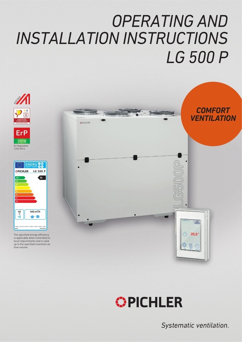
Pichler LG 500 System VENTECH User manual

Systematic ventilation.
COMFORT
VENTILATION
EN13141-7:2010
EU Regulation
1253/2014
ErP
2018
OPERATING AND
INSTALLATION INSTRUCTIONS
SYSTEM VENTECH LG 500
The specified energy eciency
is applicable when controlled to
local requirements and is valid
up to the specified maximum air
flow volume.

Contents
1Introduction ............................................................................................................................................. 4
2General .................................................................................................................................................... 4
2.1Use in compliance with the intended use .................................................................................................. 5
2.1.1
Intended use
............................................................................................................................................................5
2.1.2
Stipulations for operation with fireplaces
.................................................................................................................6
2.1.3
Stipulations in connection with extractor hoods
........................................................................................................6
2.2Liability .................................................................................................................................................... 6
2.3Warranty .................................................................................................................................................. 6
3Safety ...................................................................................................................................................... 7
3.1Symbols used ........................................................................................................................................... 7
3.2Safety regulations .................................................................................................................................... 8
3.2.1
General
....................................................................................................................................................................8
3.2.2
Setting up the unit
....................................................................................................................................................8
3.2.3
Electrical connection work
.......................................................................................................................................9
3.2.4
Operation of the system
...........................................................................................................................................9
4Functioning of the ventilation system .................................................................................................. 10
4.1System description ................................................................................................................................. 10
4.2Possibilities of system expansions for frost protection ........................................................................... 11
4.2.1
Earth heat exchanger (factory settings)
..................................................................................................................11
4.2.2
Brine geothermal energy with optional cooling function (factory setting)
................................................................12
4.2.3
PTC low temperature preheater battery factory setting
..........................................................................................13
4.2.4
Anti-frost protection by shutting down the supply air fan
........................................................................................13
4.3System expansion for the purpose of external auxiliary heating ............................................................. 14
4.3.1
With external warm water heater battery (factory setting)
......................................................................................14
4.3.2
Needs-based system operation - CO2 control
..........................................................................................................14
4.4Ventilation unit ....................................................................................................................................... 15
4.4.1
Description
............................................................................................................................................................15
4.4.2
Advantages and features
........................................................................................................................................15
4.4.3
Layout of the unit
...................................................................................................................................................16
4.4.4
Versions
.................................................................................................................................................................18
4.4.5
Dimensions
............................................................................................................................................................18
4.5Safety devices ........................................................................................................................................ 19
5Technical specifications ....................................................................................................................... 19
5.1Unit specifications .................................................................................................................................. 19
5.2Characteristic external pressure increase - air volume flow with volume flow constant function ........... 20
5.3Characteristic external pressure increase - air volume flow without volume flow constant function ...... 20
5.4Acoustic specifications ........................................................................................................................... 21
6Operator control unit ............................................................................................................................ 21
6.1General information ............................................................................................................................... 21
6.2Control unit "
KOMFORT-G
" ...................................................................................................................... 21
6.2.1
Buttons on the control unit "KOMFORT-G"
...............................................................................................................22
6.2.2
Representation on the display
................................................................................................................................22
6.2.3
Special menu 1 – Operating hour counter (only for specialist installers)
.................................................................24
6.2.4
Special menu 2 - Language settings, basic ventilation, volume flows and fan speed IV
............................................24
7Power unit ............................................................................................................................................. 25
7.1Configuration and diagnosis via the PC software (only for specialist installers) ...................................... 25
7.1.1
Connecting the power section to a PC
.....................................................................................................................25
7.1.2
Software overview
.................................................................................................................................................26
8Messages/Faults .................................................................................................................................. 26
8.1Operating messages on control unit "
KOMFORT-G
" ................................................................................. 26
8.1.1
Deletion of the filter message after a requested filter change
.................................................................................26
8.1.2
Deletion of the filter message after a premature filter change
................................................................................26
8.2Malfunction messages on control unit "
KOMFORT-G
" .............................................................................. 27
OPERATING AND INSTALLATION INSTRUCTIONS SYSTEM VENTECH LG 500 PAGE 2

9Scope of delivery, transport, storage and disposal ............................................................................ 28
9.1Scope of supply ..................................................................................................................................... 28
9.2Transport and Packaging ....................................................................................................................... 28
9.3Storage .................................................................................................................................................. 28
9.4Waste disposal ...................................................................................................................................... 28
10Installation ........................................................................................................................................... 29
10.1Prerequisites for installation of the unit ................................................................................................. 29
10.2Device installation ................................................................................................................................. 30
10.2.1
Setting up the ventilation unit - free-standing installation
....................................................................................... 30
10.2.2
Wall mounting
........................................................................................................................................................30
10.2.3
Production of the condensate water connection
.....................................................................................................30
10.2.4
Connection of air lines and components
.................................................................................................................31
10.3Electrical connection.............................................................................................................................. 31
10.3.1
Cable leadthroughs
................................................................................................................................................32
10.3.2
Connection between the operator control unit and power unit
................................................................................ 32
10.3.3
Installation of the operator control unit
.................................................................................................................. 32
10.3.4
Circuit diagram
......................................................................................................................................................33
10.3.5
Mains connection and replacement of the unit’s internal fuse
................................................................................. 36
10.3.6
Connecting a water re-heater battery
.....................................................................................................................37
10.4Initial startup ......................................................................................................................................... 37
11Servicing and cleaning ......................................................................................................................... 38
11.1Safety directions .................................................................................................................................... 38
11.2Customer service ................................................................................................................................... 38
11.3Service instructions for the user ............................................................................................................ 38
11.3.1
Air filters
...............................................................................................................................................................38
11.4Service instructions for the specialized installing company ................................................................... 39
11.4.1
Heat exchanger with bypass flap
............................................................................................................................ 39
11.4.2
Fans
......................................................................................................................................................................39
11.4.3
Electrical PTC preheater battery (optional)
............................................................................................................. 40
11.4.4
Unit’s housing - internal cleaning
...........................................................................................................................40
11.4.5
Condensate drainage
.............................................................................................................................................40
11.4.6
Service table
..........................................................................................................................................................41
12Spare parts and accessories ............................................................................................................... 42
12.1Control elements ................................................................................................................................... 42
12.2System components .............................................................................................................................. 42
12.3Air filters ............................................................................................................................................... 42
13Subject to change ................................................................................................................................. 42
14Product fiche......................................................................................................................................... 43
15EG-Konformitätserklärung (EC Declaration of Conformity) ............................................................... 44
OPERATING AND INSTALLATION INSTRUCTIONS SYSTEM VENTECH LG 500 PAGE 3

1 Introduction
Dear customer, thank you for your decision to purchase the compact ventilation unit LG 500 System
VENTECH.
The compact ventilation unit LG 500 System VENTECH is a state-of-the-art device. Its convincing features
are its high degree of economy, operator friendliness and operational safety.
To operate your compact ventilation unit safely, properly, and economically, please carefully read and comply
with these operating instructions.
Use the ventilation unit only in perfect condition, in compliance with the intended use, in a manner that is
safety and danger conscious and in compliance with all information provided in these instructions. If you have
any queries or spare parts orders, please have the device type and serial number (see type plate on the
device) at hand.
Please contact us if you have any further queries or you have lost the documentation:
2 General
This chapter contains general information on the compact ventilation unit LG 500 System VENTECH with
control unit type "
KOMFORT-G
".
READ THESE INSTRUCTIONS CAREFULLY BEFORE INITIAL STARTUP OF THE UNIT!
These instructions contain advice and information about the safe operation, installation, service and
maintenance of the compact ventilation unit LG 500 System VENTECH. It also serves as a reference for service
work so that this can be performed in a responsible manner. Please keep these operating instructions in a
safe place where they are always accessible. Any troubleshooting or work on the compact ventilation unit
must only be performed by an installation company (specialists). We are continuously improving and
developing our products. Your device may therefore differ slightly from the one referred to in these
instructions.
Subject to change without notice:
These instructions have been drawn up with the greatest care. However, no rights may be derived from them.
We constantly make every effort to make technical improvements to and optimizations of our products and
reserve the right to partially or wholly modify the units or technical specifications without prior notice.
For the compact ventilation unit LG 500 System VENTECH, our "General Terms and Conditions" in the
applicable version apply.
OPERATING AND INSTALLATION INSTRUCTIONS SYSTEM VENTECH LG 500 PAGE 4

The compact ventilation unit LG 500 System VENTECH, together with all the
optional system components cited in this description, has been subjected by TÜV-
AUSTRIA Services GmbH, Testing, Inspection and Certification Centre/Vienna to
a safety test and inspection in accordance with the relevant product requirements,
standards and directives. The mark approval certificate No. 0010-PS/PZW-EX-
0067-2010 of 8 March 2011 and test reports No. 2010-PS/PZW-EX-0067 and No.
M/EMV-10/220 confirm that the requirements of the relevant test points with the
optional system accessories are met, on the condition that the requirements of
these operating instructions are observed and adhered to
.
2.1 Use in compliance with the intended use
2.1.1 Intended use
The compact ventilation unit LG 500 System VENTECH is intended for installation into air treatments systems
with an adjustable air volume flow of 550 m³/h for the controlled mechanical ventilation of living areas and
rooms with similar purpose, such as seminar rooms and small offices.
The entire living area is provided with supply air and exhaust air ventilation by installing a mechanical,
controlled ventilation system for apartments. In this process there is a controlled air supply with conditioned
and filtered outdoor air in the supply air zones. Odours and humid indoor air are taken out of the extract air
zone.
The purpose of the controlled mechanical ventilation of living areas is to improve air quality and to reduce
heating requirements through the use of a highly efficient heat recovery system as well as influencing indoor
air humidity.
The application range and intended use of the device is limited to use in indoor air treatment systems for
exhausting consumed air and supplying fresh, temperate outdoor air at a maximum conveying temperature of
-15 °C to +35 Ԩ. In addition, the conveyed air must be free of aggressive vapours and wear-inducing
materials. Any other application shall be deemed to be diverting from the intended use. The manufacturer
shall assume no further liability for any damages or consequential damages resulting from non-intended use.
Intended use also includes observing our prescribed operating and installation instructions. This unit, which is
accessible for the general public, is intended for installation in residential or commercial buildings. The device
is used for mechanical ventilation of indoor air and also for air reheating in conjunction with a heater battery.
This device is not intended to be used by people (including children) with limited physical, sensory, or mental
capabilities or with a lack of suitable experience and/or knowledge, unless supervised by a person who is
responsible for their safety or from whom they receive instructions on how to use the device.
The unit is not suitable for installation in the open air and must be installed in suitable and temperature-
controlled indoor rooms. The ventilation unit is not suitable for drying out new-build properties. When the
device is shut down, ensure that no air circulation can occur through the device.
The compact ventilation unit LG 500 System VENTECH is not a ready-to-use product. It must not be put into
operation until it has been properly installed and connected in the indoor air treatment system. Only qualified,
assigned personnel may work on and with the device.
Any individual who transports, sets up or works on the device must have read and understood these
operating instructions, particularly Chapter 3 "Safety Instructions". In addition, the end user has to
be informed of any dangers that might occur.
OPERATING AND INSTALLATION INSTRUCTIONS SYSTEM VENTECH LG 500 PAGE 5

2.1.2 Stipulations for operation with fireplaces
Safety instructions and standards must be observed when using the device simultaneously with fireplaces
consuming indoor air. In the case of indoor air dependent fireplaces the combustion air supply for the
fireplace has to be provided separately.
Proper operation of ventilation systems based on the central “Compact ventilation unit LG 500 System
VENTECH” ventilation system requires that existing combustion air or waste gas ducts are isolated from
heating systems dependent on room air.
The ventilation unit LG 500 System VENTECH may only be installed in rooms, apartments and user units of a
comparable size in which indoor air dependent fireplaces are installed, if the simultaneous operation of
indoor air dependent fireplaces for liquid or gaseous fuels and of the apartment’s ventilation system is
prevented or the exhaust gas conveyance of the indoor air dependent fireplace is monitored by special safety
devices.
If the negative pressure in the room where the fireplace is installed is 4 Pa greater than the external pressure,
it must be ensured that the extract air system switches off automatically and reliably. In such cases, the input
"E3 fireplace mode" provided for this purpose can be used. When the contact is closed, the ventilation unit is
switched off immediately and "fireplace mode" is displayed on the control panel. When the contact is opened,
the ventilation unit returns to its original state.
2.1.3 Stipulations in connection with extractor hoods
On account of the heavy load and irregular operation the extract air of any kitchen extractor hood present
must not be integrated into the apartment’s ventilation system. The extract air from such extractor hoods
should be removed separately out of the roof via an exhaust air line. The supply air is provided separately, e.g.
via the window ventilation.
If an extractor hood is being operated without separate introduction of the supply air, the air volume balance
in the apartment is no longer balanced and the proper functioning of the apartment’s ventilation system is not
ensured (odour entrainment etc.). One possibility is to operate the extractor hood with adequate air filtering in
recirculated air mode.
2.2 Liability
The compact ventilation unit LG 500 System VENTECH has been developed and manufactured for use in the
controlled mechanical ventilation of living areas and rooms with a similar purpose, such as seminar rooms
and small offices.
Any other use is considered to be an improper use and can lead to personal injury or damage to the compact
ventilation unit LG 500, for which the manufacturer cannot be held liable. In the event of the following the
manufacturer is liable for no damage whatsoever:
non-compliance with the safety, operating and servicing instructions listed in these operating and
installation instructions
the installation of replacement parts that are not supplied by the manufacturer, whereby the
responsibility for the use of such replacement parts lies completely with the system installer/fitter.
normal wear
2.3 Warranty
The warranty begins with initial startup, at the latest, however, one month after delivery has taken place. The
warranty covers the pure replacement of materials only and does not include any claims for the
compensation of services. It applies only if there is proof of appropriately performed servicing in accordance
with our regulations and by a licensed company that specializes in installation work.
The warranty claim extends for a maximum period of 24 months after installation of the compact ventilation
unit LG 500 System VENTECH, however, up to a maximum of 30 months after the date of manufacture.
OPERATING AND INSTALLATION INSTRUCTIONS SYSTEM VENTECH LG 500 PAGE 6

Warranty claims can be asserted only for material and/or design defects that have occurred during the
warranty term. In the case of a warranty claim, the compact ventilation unit LG 500 System VENTECH may not
be removed without prior written approval of the manufacturer. The manufacturer accords a warranty on
spare parts only if they have been installed by an installer who is recognized by the manufacturer.
The warranty shall expire automatically at the end of the warranty period, or in the case of improper
operation, such as operating without filters, installation of parts not supplied by the manufacturer, or where
non-approved changes or modifications have been made to the system.
Failure to comply with these Operating and Installation Instructions will automatically void all warranties.
3 Safety
Read these operating and installation instructions carefully and observe the safety instructions for
installation work, commissioning or for general work or maintenance performed on the device.
Retain these operating and installation instructions during the entire service life of the device and keep them
in an easily-accessible location for future reference.
The safety instructions, warnings, comments and directions described in these operating instructions must
always be observed.
The specifications stated in this document may not be modified.
Non-observance of these safety instructions, warnings, comments and directions can result in physical injury
or damage to the compact ventilation unit.
We recommend purchasing a maintenance contract to ensure that the device is inspected and maintained at
regular intervals. Your supplier can provide you with the addresses of approved specialists/installers in your
area.
3.1 Symbols used
The following safety symbols indicate text passages that warn against dangers and sources of danger. Please
familiarise yourself with these symbols!
Caution/Important information!
Caution! The non-observance of this warning can lead to injury or danger to life and limb and/or
damage to the unit.
Caution - dangerous electrical voltage! The non-observance of this warning can lead to injury or
danger to life and limb.
OPERATING AND INSTALLATION INSTRUCTIONS SYSTEM VENTECH LG 500 PAGE 7

3.2 Safety regulations
3.2.1 General
Installation, commissioning, maintenance, and repair must be performed by an authorised specialist
(heating specialist firm/installation specialist firm).
The local national regulations and standards apply without restriction beyond these operating installation
instructions in respect of operation of the device. Ensure that your system installer/fitter shows you how to
operate the device and the control unit after installation. Use of the ventilation unit may only take place in
accordance with the use set out in point 2.1 ‘Use in compliance with the intended use`.
All safety and danger notices attached to the device and described in these instructions must be observed. In
the event of any malfunctions, shut down the unit immediately and secure it suitably against being switched
back on. Any malfunction of the device must be rectified immediately. After servicing and maintenance work,
the operating safety of the device should be re-established by expert personnel.
The attachment or installation of additional parts and components is not permitted. Any modifications or
changes to the compact ventilation unit LG 500 System VENTECH are prohibited. Only original replacement
parts may be used. Modifications and adaptations to the ventilation unit are not permitted and release the
manufacturer from any warranty and liability. Make sure that children do not play with the unit.
3.2.2 Setting up the unit
The national and local regulations must be observed for installation and setup.
The unit must be installed only in compliance with the national installation regulations. Installation
shall be performed in accordance with the general, locally valid construction, safety and installation
regulations of the appropriate local authority or of the water and electricity company and other institutions.
The unit may be installed only in frost-free and dry rooms. The room temperature in the set-up room must
have a continuous temperature between a minimum of +5 Ԩ and a maximum of +40 Ԩ. The device is intended
for free-standing installation or wall mounting and may only be set up when there is suitable load-bearing
floor or wall construction. No vibrations must be allowed to affect the unit. A suitable water drain with
effective drain trap (siphon) must be provided for discharging condensate water accumulated during
operation of the device.
Installation work for the water, heating and condensate water connections may only be performed by a
professional. Proper installation is essential for ensuring the water-tightness and effectiveness of the
condensate discharge line and in order to prevent damage to the building. The condensate drainage has to be
checked for operability by means of an on-site inspection prior to initial startup and after any servicing work.
The permitted maximum expectable load has to be heeded for transportation of the unit. System components
of the ventilation system, such as air lines, that are installed in potentially unheated areas must be suitably
insulated to prevent heat loss or condensate water formation (where temperatures fall below the dew point).
The locally-applicable construction and fire prevention provisions, regulations and standards must be
adhered to. Appropriate suitable measures for erection of the unit, e.g. the installation of fire dampers in air
pipes etc., may have to be taken. Take into consideration the ambient influences and do not install the
ventilation unit in the vicinity of combustible liquids or gases, in swimming pools or in areas subject to the
influence of chemicals.
OPERATING AND INSTALLATION INSTRUCTIONS SYSTEM VENTECH LG 500 PAGE 8

3.2.3 Electrical connection work
Electrical connection work and work on the electrical parts of the system may be performed only by
authorized skilled electricians in compliance with national and local regulations.
Before opening the device and during all work on the device, such as maintenance work, repairs etc., the
device must be disconnected from power (power supply disconnected at all poles) and must be secured
against being switched on again for the duration of the work.
The compact ventilation unit LG 500 is designed for a voltage supply of 230 V/50 Hz/16 A. The device is not
designed for electrical connection to a three-phase supply network with 400 V/50 Hz! Refrain from any
manner of working that impairs the safety of the unit. For safe operation, safety devices may not be
disassembled or placed out of operation.
The electrical equipment and the warning and protection devices of the unit have to be regularly checked for
perfect operability. The device must be placed out of operation immediately if malfunctions occur in the
electrical supply or defects are detected, such as loose connections or melted cables.
If the mains power cable of the device is damaged or defective, it must be repaired immediately to prevent
risks. Only genuine fuses with the prescribed current strength and dimensions may be used. Operation of the
unit is prohibited until safe operation of the system has been re-created.
Only qualified electrical specialists may determine the cause of occurring defects and malfunctions and
immediately rectify them. After electrical work has been performed, the safety measures on the device must
be checked (e.g. earthing resistance etc.).
3.2.4 Operation of the system
Operation of the ventilation unit is only permitted if all required connections in conjunction with the
provided installed components, such as sound absorbers etc., have been properly established.
Upon the occurrence of any defects or damage that are able to injure people or damage property, the system
has to be put out of operation immediately. Further operation must be effectively prevented until the device is
completely repaired! Where fault messages or damage occur, the device must be immediately switched off
and disconnected from the mains.
When opening the front covers or removing cover plates, act in a safety-conscious manner and be aware of
the risks. Every working method that impairs safety is prohibited. Operation of the device is only permitted
with a connected air line or installed system components, such as sound absorbers, with a minimum line
length of 1000 mm to ensure that the fans or electrical components, for example, cannot be touched by hand.
The ventilation unit must be operated only in compliance with the project documents. These must comply with
the equipment and product safety act and with the relevant applicable stipulations of the EC directives and
standards.
Never operate the ventilation unit without installed air filters. The air filters must be checked regularly for
contamination and damage and cleaned or replaced if necessary. The air filters are to be replaced at least
every six months or when the "filter change" message appears on the control unit. Use only genuine spare
filters. If the system is not in operation in the summer, for hygienic reasons the air filters have to be replaced
before putting it back into operation.
In case of simultaneous use of the ventilation unit with fireplaces consuming indoor air, the applicable safety
instructions and standards must be observed. In the case of indoor air dependent fireplaces the combustion
air supply has to be provided separately. Advice on this is provided under
point
2.1.2 "Provisions for
operation with fireplaces".
Owing to their heavy loading and irregular operation, extractor hoods must not be integrated into the extract
air or exhaust air circuit of the ventilation unit. Advice on this is provided under
point
2.1.3 "Provisions for
use with extractor hoods
" . Exhaust air extractor hoods must be operated via separate air lines, with
provision for a suitable fresh air supply, e.g. by opening windows, or via suitable air filters in recirculated air
mode.
OPERATING AND INSTALLATION INSTRUCTIONS SYSTEM VENTECH LG 500 PAGE 9

4 Functioning of the ventilation system
4.1 System description
In the case of mechanically controlled apartment ventilation the consumed, humid extract air from the wet
rooms of the apartment, e.g. bathroom, toilet and kitchen, is discharged and replaced by conditioned, fresh
and filtered outdoor air in the residential areas such as the lounge, bedrooms and other living areas.
High energy savings in the operation of the ventilation unit can be realised through needs-based system
operation, the use of a highly efficient heat exchanger for the recovery of heat from the extract air into the
supply air and the use of energy-efficient fans with the latest EC technology.
It should be particularly ensured that the highly efficient heat exchanger is protected against freezing via a
suitable, controlled frost-protection strategy and that an effective condensate water outlet, among other
measures, is in place. The more airtight the building shell and the more effectively a house is insulated, the
more effective this technology is.
Fig 1 - Circuit diagram of system components
The circuit diagram illustrates the fundamental design of the domestic ventilation unit with the optional
additional system enhancements.
1 - Unit’s housing
2 - Supply air fan in EC execution
3 - Extract air fan in EC execution
4 - Outdoor air filter for fine dust F7
(optional as pollen filter in quality category F9)
5 -Extract air filter G4 for coarse dust
6 - Counterflow heat exchanger
7 - Bypass flap
8 - Frost pre-heating for counterflow - heat exchanger (optional)
9 - Condensate water tank with discharge and drain trap
(siphon) supplied by the customer
10 - Connection pieces for the ventilation unit
11 - Sound absorbers (optional) in the line system
12 - Switchable flap (optional)
13 - Re-heater battery design with warm water (optional)
with downstream supply air temperature sensor
14 - Earth heat exchanger (optional)
15 - Suction element with pre-filter G4
16 - Heater, cooling battery for brine EHE
(earth heat exchanger) (optional)
OPERATING AND INSTALLATION INSTRUCTIONS SYSTEM VENTECH LG 500 PAGE 10

4.2 Possibilities of system expansions for frost protection
Particularly in the winter months, moderate to heavy frosts can pose a risk of freezing on the
exhaust air side of the heat exchanger depending on the extract air temperature and extract air
humidity. Where outdoor air temperatures fall to approximately -3 °C, the heat exchanger must be
protected by suitable measures against the formation of ice.
Various systems can be used for defrost monitoring of the heat exchanger. Possible strategies to counteract
freezing of the heat exchanger are described below:
4.2.1 Earth heat exchanger (factory settings)
Optimal frost protection in the presence of cold outdoor air temperatures can be realized by the integration of
an earth heat exchanger into the ventilation system. Additional components, such as a PTC pre-heater battery
integrated into the ventilation system, are then unnecessary.
In summer mode, the cooling effect of an earth heat exchanger is very limited and barely noticeable
for the user due to the low air exchange.
The following information has to be heeded for design of the earth heat exchanger:
Watertight pipes are laid underground at frost-free depth, in consideration of the cleanability of the
system
The design guidelines of the manufacturer have to be complied with
Provision should be made for condensate water discharge
When taking air lines through external walls, ensure an effective seal to prevent the entry of moisture
To avoid frost damage, a sufficient distance from other components such as water pipes, foundations
etc. has to be maintained when laying
In the event of polluted soil (e.g. radon incidence) the possibility of indirect preheating, e.g. a circuit
system with a frost protected heat transfer medium should be used by preference
Earth heat exchangers must be carefully planned and executed with respect to their energy efficiency and air
hygiene. The relevant directives and standards have to be complied with.
In particular, among other things, attention has to be paid to easy cleanability and a suitable filter concept.
EHE winter mode:
The earth heat exchanger is engaged via the switchable flap when the outdoor air temperature drops below
the parameterized EHE winter threshold value. In this case the outdoor air is drawn in via the earth heat
exchanger and preheated in the process. If the outdoor temperature (optional sensor AI9 required) falls below
the parameter EHE-winter 6 °C, the relay K8 switches on the earth heat exchanger (EHE).
EHE summer mode
In the summer the earth heat exchanger is engaged when the outdoor temperature rises above the
parameterized EHE summer threshold value. In this case the outdoor air that is drawn in is precooled via the
earth heat exchanger. If the outdoor temperature (optional sensor AI9 required) moves above the parameter
EHE-summer 20 Ԩ, the relay K8 switches on the earth heat exchanger (EHE).
An additional external outdoor temperature sensor (part. No.: 40LG040050) must be installed
outside. This sensor is connected to the input AI9 (outdoor temperature) which is automatically
recognised by the controls. The change-over valve (Fig 1 - Circuit diagram of system components
ref. 12) is then regulated by this temperature sensor.
OPERATING AND INSTALLATION INSTRUCTIONS SYSTEM VENTECH LG 500 PAGE 11

4.2.2 Brine geothermal energy with optional cooling function (factory setting)
In the winter, brine geothermal energy systems draw the energy from the ground via a brine pipeline; in the
summer, the system can also be utilised for cooling purposes. The heat or cold is transferred indirectly to the
supply air via an external air register integrated into the air line system.
Compared to other frost protection strategies such as electric preheater batteries or hot water preheater
batteries, brine earth heat systems have the advantage that they can make do with little energy when in
operation. The advantage in contrast to the air channel earth heat exchanger lies in hygienic aspects, the
simpler layout and good controllability.
In the event of polluted soil (e.g. radon incidence) it is preferential to use indirect preheating, e.g. a circuit
system with a frost protected heat transfer medium.
The design guidelines of the manufacturer have to be complied with. The brine heater battery should be
protected against contamination via an external air filter integrated into the air line system with a filter quality
category of at least G4. The basic system components are shown in the following diagram:
Fig 2 - Circuit diagram of brine geothermal energy with optional cooling function
Brine pump controlled automatically depending on outdoor temperature; optional sensor AI9 required.
Brine earth heat winter mode:
If the outdoor temperature (optional sensor AI9 required) falls below the parameter EHE-winter 6°C, the relay
K8 switches on the brine pump.
Brine earth heat summer mode:
If the outdoor temperature (optional sensor AI9 required) exceeds the parameter EHE-summer 20Ԩ, the relay
K8 switches on the brine pump.
An additional external outdoor temperature sensor (part. No.: 40LG040050) must be installed
outside. This sensor is connected to the input AI9 (outdoor temperature) which is automatically
recognised by the controls. The brine pump is then controlled via this temperature sensor.
OPERATING AND INSTALLATION INSTRUCTIONS SYSTEM VENTECH LG 500 PAGE 12

4.2.3 PTC low temperature preheater battery factory setting
The ventilation unit LG 500 System VENTECH can be optionally supplied with an integrated electric PTC
pre-heater battery. If the optional pre-heater battery is installed, the cold outdoor air is pre-heated via the
integrated electric PTC pre-heater battery if there is a risk of frost for the heat exchanger.
With this operating mode a balanced air volume flow is ensured between the supply air and extract
air for the defrosting time period!
Frost protection via integrated PTC pre-heater battery:
the temperature sensor AI4 (outdoor air temperature in the unit) is relevant for the de-icing
function.
the temperature sensor AI4 is positioned on the outdoor air inlet of the heat exchanger.
when the outdoor air inlet temperature is below -3 °C and the outlet temperatures at the exhaust air
sensor AI5 are below +5.5 °C, the PTC pre-heater battery is enabled and Stage I of the PTC pre-
heater battery is switched on.
the air temperature at the sensor AI4 is constantly regulated between 0.5 °C and -2.5 °C.
to achieve this, up to 6 different heating stages are switched on and off automatically on the PTC
pre-heater battery, according to the outdoor air temperature, via the control system.
erroneous operation of the PTC pre-heater battery is monitored via the exhaust air sensor AI5
the pre-heater battery is only enabled when the air temperature at the exhaust air sensor AI5 falls
below +5.5 °C.
4.2.4 Anti-frost protection by shutting down the supply air fan
CAUTION: This operating mode is not suitable for frost protection in passive houses or
buildings with an air-tight design!
The compact ventilation unit LG 500 System VENTECH is equipped as standard with automatic frost-protection
for the heat exchanger by shutting down the supply air fan while the extract air volume flow remains constant.
These measures prevent the heat exchanger from freezing. If, however, this operating setting does not
achieve reliable de-icing, the system will be shut down for approx. 8 hours. The system will be switched on
again automatically.
To achieve reliable de-icing, a motorised shut-off valve should be integrated into the outdoor air line. This
valve will be controlled automatically via the controls and prevent the possible entry of outdoor air. This
function must be activated via the PC software (see 7.1).
In this operating mode an equalised air volume flow balance between the supply air and extract
air during the period of de-icing is not ensured!
Frost protection via extract air de-icing by shutting down the supply air fan:
the temperature sensor AI4 (outdoor air temperature in the device) is relevant for the de-icing
function
the temperature sensor AI4 is positioned on the outdoor air inlet of the heat exchanger
when inlet temperatures at the sensor AI4 are colder than -3 °C and outlet temperatures at the
exhaust air sensor AI5 are colder than +5.5 °C, the de-icing cycle is enabled
the de-icing process is only commenced when the temperature difference between the extract air
and supply air exceeds 6 °C.
once the de-icing shutdown period (15 min) is complete, the supply air fan is switched back on.
OPERATING AND INSTALLATION INSTRUCTIONS SYSTEM VENTECH LG 500 PAGE 13

---- Notification ----
frost protection switched off
4.3 System expansion for the purpose of external auxiliary heating
In order to be able to increase the air outlet temperature for the living area further after the heat exchanger,
additional external heating can be installed. This afterheating can be achieved via an external warm water
heater battery integrated into the air line system.
4.3.1 With external warm water heater battery (factory setting)
The supply air temperature can be increased further via an external, optional water re-heater battery and 3-
point mixer control, which is installed in the supply air line downstream of the ventilation unit.
The set value for the temperature and recording of the room temperature is set via the "
KOMFORT-G
" control
unit, which has the room temperature sensor integrated into it. The temperature set value for the room
temperature can be set within a range of +10 °C to +35 °C. In the "Service menu" under Control, you can
select between room temperature control and supply air temperature control (see point 6.2.5).
The mixer works in a clocked control mode with PID control circuit. The control parameters are factory set for
a mixer with a runtime of 120 seconds and can be adjusted via the PC software (see point 7.1).
This operating mode requires an additional external temperature sensor type KTY8110, length 5 m
(part. No.: 40LG040370) to be installed downstream of the re-heater battery in the air line. The
sensor is connected to the input AI6 (temperature sensor RHB (re-heater battery)) and recognised
automatically by the the controls. The supply air temperature is then controlled via this sensor.
If a warm water heater battery is connected, the re-heater battery can be protected against risk of frost for
additional security via the potential-free input "E2". If this potential-free contact is closed via an external
temperature sensor, which must be set to a trigger temperature of +5 °C, the ventilation unit will emit a "Frost
shutdown" fault message.
This customer-supplied sensor is positioned immediately in front of the
external heater battery in the air line system. In this "frost protection"
fault state, the mixer will be 100 % open and the circulation pump
activated. The fans are switched off until the frost danger message drops away again.
The same frost protection strategy is also applied with a temperature of below +5 °C at the integrated supply
air sensor AI3 or at the external supply air sensor RHB.
4.3.2 Needs-based system operation - CO2 control
The air volume flow can be controlled via optional accessories with surface-
mounted housing, the "CO2 sensor module“, the "humidity sensor module“,
the "CO2 and humidity sensor module“. Needs-based operation via the CO2
and/or humidity control sensor module only functions in automatic
mode and must be activated via the PC software.
A maximum of 10 sensors can be connected, with the highest value for
each fan speed is used. The measured CO2 – and/or humidity-
concentration is used to regulate the fan speed in accordance with the
table. The assignment of the fan speeds, the ppm and humidity values can
be changed via the PC software.
When using humidity sensors the priority can be selected on air quality
(factory setting) or humidity control (regulation to set humidity) on the
control panel.
14 : 30 Di 04.08.09
automatic mode
fan step II
ventilation 24° C
OPERATING AND INSTALLATION INSTRUCTIONS SYSTEM VENTECH LG 500 PAGE 14

Example:
Sensors adjustment CO2-Sensor
0 - 2000
Humidity Sensor
0 - 100
CO2- and Humidity Sensor
Fan speed CO2 in ppm Relative humidity in %
0 < 400 < 25
1 401 - 600 26 - 35
2 601 - 900 36 - 50
3 901 - 1500 51 - 65 on request
4 > 1500 > 65
4.4 Ventilation unit
4.4.1 Description
The compact ventilation unit LG 500 System VENTECH is used for the controlled mechanical ventilation of
houses, larger residential units, offices, surgeries and similar applications. The range of use extends
fundamentally to residential areas of 150 m² up to approx. 400 m², with an
adjustable air volume flow up to 550 m³/h.
The compact ventilation unit LG 500 System VENTECH, consists of a compact,
heat bridge-free and heat-insulated housing made from zinc-plated steel plate,
powder-coated exterior in RAL 9010, a highly efficient heat recovery system
with air/air counterflow heat exchanger made from recyclable plastic with an
efficiency level of approximately 92 %, an automatic 100 % bypass with energy-
saving radial fans in direct-current technology and EC technology with optional
constant flow volume regulation, air filters in quality category F7 in the supply
air and G4 in the extract air with integrated, wired, control electronics and an
optional "KOMFORT-G" remote control panel, for free-standing or wall mounting
in frost-free rooms.
4.4.2 Advantages and features
•With PHI passive house certificate and CH energy cluster declaration
•Ventilation unit with highly efficient energy recovery
•Supply air and extract air fans with energy-saving EC motors
•4-stage fan operation without constant volume flow function
•Optional with constant pressure control or electronic volume flow control for
constant air volume flow, adjustable up to 550 m³/h.
•Even with changes in the system pressure is the programmed air volume flow
maintained, for example, if the filter is dirty.
•Needs-based air volume control via CO2 sensor
•User-friendly "
KOMFORT-G
" control unit with integrated room temperature sensor
•Integrated 100 % bypass for bypassing the heat exchanger in summer mode
•Selectable, automatically operating frost protection switch for the heat exchanger,
optionally available with a PTC low temperature preheater battery
•Filter monitoring integrated, upon attainment of the time interval message ‘Filter
change’ appears on the display.
•Simple filter change without tools
•Optional reheater battery for additional raising of the room temperature
OPERATING AND INSTALLATION INSTRUCTIONS SYSTEM VENTECH LG 500 PAGE 15
0 - 2000 / 0 - 100
on request
on request
on request
on request
CO2 in ppm /
Relative humidity in %
1 2 2
Measuring sensor

4.4.3 Layout of the unit
1. Operator control unit type ‘
KOMFORT-G
’
2. Power unit
3. Connecting lead Y(ST)Y2x2x0.64
4. Outdoor air filter of quality class F7
5. Extract air filter of quality class G4
6. Counterflow heat exchanger
7. Condensate tank with discharge fitting
8. Frost protection heating with a PTC low temperature
preheater battery (optional)
9. Bypass valve with actuator
10. Outdoor air and supply air fan
11. Exhaust air and extract air fan
12. Pressure sensor for volume flow constant function (optional)
13. Exhaust-air-side sound absorber insert (optional)
14. Front cover with a knurled screw fastener
15. Air line connection
16. Cable leadthroughs
1. Operator control unit type ‘
KOMFORT-G
’
The "
KOMFORT-G
" control unit fitted directly in the living area is used to make settings for the ventilation unit.
The current operational statuses and system values, e.g. operating mode, fan speed, temperatures, etc., are
shown on the four-digit display. Operation (green), faults and filter change (flashing red) are displayed by way
of signal lamps. Automatic or manual mode can be selected. In automatic mode the system operates fully
automatically in accordance with programmable time programs, while in manual mode the fan speed, for
example, can be increased individually (air blast ventilation). The "
KOMFORT-G
" control unit can also be used
to make individual operating parameter settings during servicing work.
2. Power unit
The individual operating parameters are set by the skilled installer or service technician, matched to the
relevant application on site, via the power unit installed in the ventilation unit. The settings can be made either
via the "
KOMFORT-G
" control unit or via the PC interface and communication software.
3. Connecting lead Y(ST)Y2x2x0.64 (not included in the scope of supply)
A screened cable Y(ST)Y2x2x0.64 is required for communication between the operator control unit and the
power unit. The connecting cable is not included in the scope of supply. The cable length must not be longer
than 100 m. The plug connection to the power unit and to the operator control unit is by means of an IDE
connector.
4. Outdoor air filter of quality class F7
(
optional pollen filter of quality class F9)
The outdoor air filter removes dust and contamination from the outdoor air.
2
6
5
4
7
8
12
14
9
10
11
15
16 13
1
OPERATING AND INSTALLATION INSTRUCTIONS SYSTEM VENTECH LG 500 PAGE 16

5. Extract air filter of quality class G4 (optional F5)
Coarse contamination is filtered out of the extract air via the extract air filter.
6. Counterflow heat exchanger
The highly-efficient heat exchanger removes the energy content from the extract air and transfers this into
the supply air.
7. Condensate tank with discharge fitting
Any condensate incurred in the heat exchanger during operation is collected via the condensate trough. The
condensate incurred is discharged via the connected condensate drainage system, which is routed via an
effective odour trap.
8. Frost protection heating with a PTC low temperature preheater battery (optional)
In very cold outdoor air temperatures, protects against freezing of condensate in the heat exchanger. The
outdoor air is pre-heated, depending on the outdoor air temperature, via the optional electrical PTC low-
temperature pre-heater battery.
If a water battery or brine battery is used for frost protection the heat exchanger, the battery has to
be protected in a suitable way against freezing when there is frost.
9. Bypass valve with actuator
In summer mode, enables the bypassing of the air flow to the heat exchanger, provided that the outdoor air
temperature is lower than the room temperature.
10. Outdoor air and supply air fan
Ensures the air volume flow for the supply air; provides the living spaces with conditioned outdoor air.
11. Exhaust air and extract air fan
Ensures the air volume flow for the extract air; conveys the consumed air externally out of the apartment.
12. Pressure sensor for volume flow constant function (optional)
Measured value sensor and pressure sensors for the optional definable volume flow constant function of the
fans.
13. Exhaust-air-side sound absorber insert (optional)
For noise reduction in the vicinity of the exhaust air fan.
14. Front cover with a knurled screw fastener
The front cover can be easily opened for maintenance work to the device, e.g. filter exchange. When closing it,
make sure of complete fastening and sufficient seal tightness between the front cover and the unit’s housing.
15. Air line connection
Is for the purpose of connection to the air line system. When installing, ensure correct connection to the
supply, extract, outdoor air and exhaust air lines.
16. Cable leadthroughs
Fundamentally the ventilation unit is supplied electrically ready wired. The cable leadthroughs are used for
making the electrical connection, for connecting the operator control unit and the optional system
accessories, for example, temperature sensors etc.
OPERATING AND INSTALLATION INSTRUCTIONS SYSTEM VENTECH LG 500 PAGE 17

4.4.4 Versions
The compact ventilation unit LG 500 System VENTECH is available in several different versions:
right-hand or left-hand, depending on the location of the supply air connecting piece,
with or without electrical PTC pre-heater battery integrated into the ventilation unit for frost
protection of the heat exchanger
the device may also be optionally equipped with the following additional functions:
pressure sensor technology for volume flow or pressure constant function
exhaust-air-side sound absorber insert
needs-based ventilation operation via CO2 sensor
Version Right-hand version Left-hand version
Part no. without
integrated PTC pre-
heater battery
08LG500-R 08LG500-L
Item no. with an
integrated PTC
preheater battery
08LG500-RV 08LG500-LV
For standing or
wall-mounted
installation
4.4.5 Dimensions
Illustration with optional PTC low-temperature pre-heater battery, sound absorption unit for exhaust air side
and pressure sensor for extract air and supply air.
1 Supply air dia. 200 mm
2 Extract air dia. 200 mm
3 Outdoor air dia. 200 mm
4 Exhaust air dia. 200 mm
5 Counterflow heat exchanger
6 Extract air fan
7 Supply air fan
8 Control unit
9 Extract air filter G4
10 Outdoor air filter F7
11 Condensate trough
12 Condensate connector ø 15 mm
13 Cable entry 6 x M16
14 PTC electrical preheater battery (optional)
15 Sound absorber insert for EHA
16 Height-adjustable feet
17 Supply air pressure sensor (optional)
18 Extract air pressure sensor (optional)
Illustration: LG 500-RV (right-hand version)
OPERATING AND INSTALLATION INSTRUCTIONS SYSTEM VENTECH LG 500 PAGE 18

Page 19 of 44
4.5 Safety devices
For the purpose of ensuring safe operation of the system the safety devices and covers must not be put out of
service, bypassed or dismantled by any measures.
The system must be shut down immediately if faults or malfunctions occur in the ventilation system that could
pose a risk to persons or property.
Further operation must be effectively prevented until a complete repair has been made! Repair may only be
performed by a skilled installer.
Overheating protection. A thermo bi-metal switch is built in to
protect the optionally-integrated frost protection heater battery
from overheating. When a temperature of +50 °C is reached, this
element interrupts the power supply to the PTC electric heater battery.
5 Technical specifications
5.1 Unit specifications
Ventilation unit
Dimensions (w x h x d) 915 x 855 x 655 mm
Housing of single-shell construction made of galvanized sheet
steel, coated in RAL 9010 – white Insulation 25 mm / 30 mm
Air line connection 4 x dia. 200 mm
Condensate connection dia. 15 mm at bottom
Voltage / frequency / current 230 V / 50 Hz / 16 A
Degree of protection IP 20
Permitted ambient temperature for unit 5 °C to +40 °C
permissible air temperatures -15 °C to +35 °C
Weight without accessories 75 kg
Operator control unit „
KOMFORT-G
"
Dimensions (w x h x d) 150 x 82 x 20 mm
Connecting cable to the power unit Cable Y(ST)Y2x2x0.64, screened, max. length < 100 m
Air filters
Outdoor air/supply air filter Pocket filters quality category F7, optional quality category F9
Extract air filter Pocket filters quality category G4
Fans (factory setting)
Fan speed Speed I Speed II Speed III Speed IV
Air volume flow [m³/h] 200 300 400 500
Output in [W] with external 50/100 Pa 50/65 80/100 130/155 210/235
Air volume flow setting range 150 to 550 m³/h, settable
in increments of 5 m³/h.
Flow efficiency in accordance with PHI 0.33 W/m³/h
Power consumption in standby mode 2.9 W
OPERATING AND INSTALLATION INSTRUCTIONS SYSTEM VENTECH LG 500 PAGE 19

Heat exchanger
Counterflow heat exchanger made of plastic
Degree of heat provision in accordance with
PHI 82 %
Comfort criterion in accordance with PHI T SAir= +16.5 Ԩ where T FAir= -10 °C
Degree of recovery in accordance with EN 308
(where extract air is 21 °C / 40 % RH)
Housing seal-tightness (according to PHI where nominal air volume flow is 366 m³/h)
external seal-tightness at 100 Pa < 0,6 %
external seal-tightness at 100 Pa < 0,5 %
5.2 Characteristic external pressure increase - air volume flow with volume flow constant
function
5.3 Characteristic external pressure increase - air volume flow without volume flow
constant function
The characteristics illustrated are applicable for the device
design with pressure sensor technology for volume flow
constant regulation, supply air filter quality category F7,
extract air filter quality category G4 and the design with PTC
pre-heater battery in bypass mode. The SFP values shown
take into account power consumption for both fans for supply
air and extract air as well as the power consumption of the
control unit.
The characteristics illustrated are applicable for the device
design with supply air filter quality category F7, extract air
filter quality category G4 and the design with PTC pre-heater
battery in bypass mode.
The SFP values shown take into account power consumption
for both fans for supply air and extract air as well as the power
consumption of the control unit.
OPERATING AND INSTALLATION INSTRUCTIONS SYSTEM VENTECH LG 500 PAGE 20
Other manuals for LG 500 System VENTECH
2
Table of contents
Other Pichler Fan manuals

Pichler
Pichler LBE 250AO Specification sheet

Pichler
Pichler LG 740 Specification sheet

Pichler
Pichler LG 100 AP Specification sheet

Pichler
Pichler LG 500 System VENTECH User manual

Pichler
Pichler LG 350 User manual

Pichler
Pichler LG 100 DE Specification sheet

Pichler
Pichler LG 350 User manual

Pichler
Pichler LG Series User manual

Pichler
Pichler LG 100 UP Specification sheet

Pichler
Pichler LG 500 System VENTECH User manual