manuals.online logo
Brands
  1. Home
  2. •
  3. Brands
  4. •
  5. Pichler
  6. •
  7. Fan
  8. •
  9. Pichler LG 750 User manual

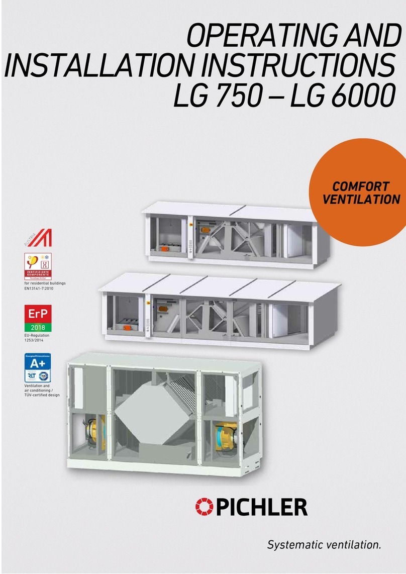
Pichler LG 750 User manual

ErP
2018
Systematic ventilation.
COMFORT
VENTILATION
EU Regulation
1253/2014
EN13141-7:2010
for residential buildings
for non-residential buildings
OPERATING AND
INSTALLATION INSTRUCTIONS
LG 750 - LG 6000
Contents
OPERATING AND INSTALLATION INSTRUCTIONS LG 750 - LG 6000 PAGE 2
Introduction.......................................................................................................................................................................4
1 General .................................................................................................................................................................4
1.1 Designated use.....................................................................................................................................................5
1.2 Liability...................................................................................................................................................................5
1.3 Warranty................................................................................................................................................................5
1.4 Warranty provisions.............................................................................................................................................5
2 Safety ....................................................................................................................................................................6
2.1 Symbols used in this document ....................................................................................................................6
2.2 Safety regulations..............................................................................................................................................6
2.2.1
General ....................................................................................................................................................................................6
2.2.2
Setting up the unit................................................................................................................................................................7
2.2.3
Electrical connections.........................................................................................................................................................7
2.2.4
Plant operation......................................................................................................................................................................8
3 Ventilation system functionality ....................................................................................................................8
3.1 System description.............................................................................................................................................. 8
3.2 System extensions for frost protection..............................................................................................................9
3.2.1
Frost protection via heat exchanger bypass .......................................................................................................................9
3.2.2
Frost protection via water pre-heating exchanger (optional) ..........................................................................................10
3.2.3
Frost protection via electric pre-heating exchanger (optional)...............................................................................12
3.3 Optional: System extension for external auxiliary heating.......................................................................... 14
3.3.1
Post heating via pumped hot water re-heating exchanger (PWW-NHR)...............................................................14
3.3.2
Re-heating using electrical heating .......................................................................................................................16
3.4 Optional: System extension for cooling ......................................................................................................... 18
3.4.1
Cooling with water cooling exchanger...................................................................................................................18
3.4.2
DX cooling (cooling unit) .......................................................................................................................................19
3.5 Heat exchanger................................................................................................................................................. 19
3.6 Optional: Demand-driven plant operation...................................................................................................... 20
3.6.1
Constant CO2 value..............................................................................................................................................20
3.6.2
Fan optimiser.........................................................................................................................................................20
3.6.3
GreenZone/PI zone modules, PI optimisers..........................................................................................................20
3.7 Optional: Building automation - networking................................................................................................... 20
4 Ventilation unit ................................................................................................................................................ 21
4.1 Description......................................................................................................................................................... 21
4.2 Unit configuration with subassemblies Series LG 750 – LG 6000............................................................. 22
4.3 Technical data Series LG 750 to LG 6000.................................................................................................... 22
4.4 Series LG 750 – LG 6000 versions................................................................................................................ 23
4.4.1
Modular units series.............................................................................................................................................................23
4.4.2
4.5 Compact units series System Mono-Case........................................................................................................................23
Air volume flow characteristics – external pressure increase: Without constant flow
volume function..................................................................................................................................................24
5 Control units....................................................................................................................................................25
5.1 General information .......................................................................................................................................... 25
5.2 Operator control unit PI-HMI............................................................................................................................ 25
5.2.1 Operation............................................................................................................................................................................... 25
5.2.2
Fan speed ............................................................................................................................................................................. 25
5.2.3
Temperature..........................................................................................................................................................................26
5.2.4
Settings..................................................................................................................................................................................26
5.2.5
Installation on flat surface ....................................................................................................................................................32
5.2.6
Installation in wall box/panel front...................................................................................................................................... 32
5.2.7
Modbus connection.............................................................................................................................................................. 33
5.2.8
Modbus RJ12 6P4C............................................................................................................................................................. 33
5.2.9
Modbus screw terminals...................................................................................................................................................... 33
5.2.10
Technical data....................................................................................................................................................................... 34
5.2.11
Service and maintenance.................................................................................................................................................... 34
5.3 Operator control unit “Pichler handheld terminal”.........................................................................................35
5.3.1
Display & operation.............................................................................................................................................................. 35
Gerätekarte:
Gerätespezifische Details zu Ihrem Lüftungsgerät entnehmen Sie der Gerätekarte!
OPERATING AND INSTALLATION INSTRUCTIONS LG 750 - LG 6000 PAGE 3
5.3.2
Operation on user level:.......................................................................................................................................................35
5.3.3
Installation / Assembly.........................................................................................................................................................36
5.3.4
Communication / Modbus.................................................................................................................................................... 36
5.3.5
LED displays ......................................................................................................................................................................... 36
6 Alarms / malfunctions....................................................................................................................................37
6.1 Operator control unit „PI-HMI“.........................................................................................................................37
6.2 Operator control unit “Pichler handheld terminal”.........................................................................................37
6.3 Optional: Alarm log in the web server............................................................................................................37
7 Scope of supply, transport, storage and disposal.................................................................................38
7.1 Scope of supply.................................................................................................................................................38
7.2 Packaging & transport ......................................................................................................................................39
7.3 Storage................................................................................................................................................................39
7.4 Disposal.............................................................................................................................................................. 39
8 Installation ........................................................................................................................................................ 40
8.1 Prerequisites for installation of the unit / interior installation....................................................................... 40
8.2 Unit installation – free-standing installation................................................................................................... 41
8.2.1
Making the condensate water connection .............................................................................................................41
8.3 Electrical connection......................................................................................................................................... 42
8.3.1
Cable feed-throughs..............................................................................................................................................42
8.3.2
Circuit diagram......................................................................................................................................................42
8.3.3
Mains connection ..................................................................................................................................................42
9 Commissioning................................................................................................................................................ 44
9.1 Basic procedure for commissioning by a specialist:..................................................................................... 44
9.1.1
Checking prior to commissioning....................................................................................................................................... 44
9.1.2
Setting the system parameters .......................................................................................................................................... 44
9.1.3
Cable feed-throughs............................................................................................................................................................ 44
9.1.4
Counter-current plate heat exchanger .............................................................................................................................. 44
9.1.5
Condensate tray................................................................................................................................................................... 44
9.1.6
Fans....................................................................................................................................................................................... 45
9.1.7
Housing front/door ............................................................................................................................................................... 45
9.2 Connecting air ducts and components........................................................................................................... 45
10 Decommissioning / servicing / cleaning................................................................................................... 46
10.1 Customer service...............................................................................................................................................46
10.2 Service instructions for the specialist company............................................................................................ 46
10.2.1
Outdoor and extract air compact filters............................................................................................................................. 46
10.2.2
Fans....................................................................................................................................................................................... 47
10.2.3
Counter flow plate heat exchanger with bypass plate .................................................................................................... 48
10.2.4
Pre- and re-heating battery................................................................................................................................................. 48
10.2.5
Bypass plate, exhaust air plate, outdoor air plates.......................................................................................................... 48
10.2.6
Condensate tray................................................................................................................................................................... 48
10.2.7
Servo motors .........................................................................................................................................................................48
10.2.8
Cleaning the inside of the unit............................................................................................................................................ 48
11 Service table..................................................................................................................................................... 49
12 Spare parts and accessories – see unit card........................................................................................... 50
13 Overview of PI-Air-2 functions..................................................................................................................... 51
14 Changes reserved........................................................................................................................................... 52
15 Product fiches...................................................................................................................................................53
15.1 Product fiche LG 750.........................................................................................................................................53
15.2 Product fiche LG 1000...................................................................................................................................... 55
15.3 Product fiche LG 2500...................................................................................................................................... 57
15.4 Product fiche LG 4000...................................................................................................................................... 59
15.5 Product fiche LG 6000...................................................................................................................................... 61
Illus.: LG 1000 nameplate
1 General
Although this Manual has been compiled with the utmost care, this does not imply any guarantees. We
constantly strive to improve and optimise our products technically and we reserve the right to modify our
units or technical data fully or in part and without prior notification. Our “General Terms and Conditions” as
amended shall apply to the Series LG 750 – LG 6000 ventilation units.
In case of further questions or lost documentation, please contact:
J. Pichler Gesellschaft m.b.H., Karlweg 5, 9021 Klagenfurt – T +43 (0)463 32 7 69 – office@pichlerluft.at
Changes reserved
Introduction
Dear Customer, thank you for purchasing a Series LG 750 – LG 6000 ventilation unit.
Series LG ventilation units are state-of-the-art. They are convincing by their high cost effectiveness,
ease of use and reliable operation.
Please read this manual carefully and follow the instructions to ensure the safe, reliable and economic operation
of your ventilation system.
Do not use your ventilation system unless in perfect condition and use only as designated; be aware
of safety issues and any hazards and familiarise yourself with the notes and information contained in
this Manual.
Please always keep the model and serial number (see nameplate on unit) at hand, in case of queries or when
ordering spare parts.
PLEASE READ THIS MANUAL CAREFULLY PRIOR TO COMMISSIONING AND HEED THE
SAFETY INSTRUCTIONS!
This Manual contains notes and information on safe operation and proper installation of the Series LG
ventilation unit and on its use and servicing. Reference this Manual during servicing to ensure proper
execution of the tasks. Keep this Operating Manual in a safe place and readily available at all times.
Any interventions and remedial actions on the ventilation unit shall be done by a specialised installation company.
These units are subject to ongoing improvement and further development. Your unit may therefore vary
slightly from the description in this Manual.
OPERATING AND INSTALLATION INSTRUCTIONS LG 750 - LG 6000 PAGE 4
1.1
Designated use
The ventilation unit’s applications and designated use are limited to the deployment and operation for
mechanical ventilation and extraction of air in residential and non-residential buildings. The ventilation unit may
not be used for drying, since the unit is not designed for dehumidifying. The conveyed air at minimum and
maximum temperatures of -16°C to + 35°C resp. must be free of aggressive vapours and substances causing
wear.
Any other use shall be deemed contrary to designated use. The manufacturer shall accept no responsibility for
damages or consequential damages arising from improper use. Designated use shall also include compliance
with our prescribed Operating and Installation Manual.
This unit is available to the general public and is intended for installation in residential or industrial buildings.
The unit is used for mechanical aeration and ventilation of ambient air and, combined with a heating and
cooling battery, also for re-heating/cooling of the air.
This unit is not intended for use by persons, including children, with limited physical, sensory or mental
capacities or lacking experience and/or knowledge, unless under supervision or instruction of a person
responsible for their safety.
Series LG ventilation units are not ready-to-use products. They shall not be started up unless after proper
installation and connection in the ventilation and air conditioning system. Only qualified and instructed persons
may work on and with the unit.
Persons transporting or working on the unit must have read and understood the Operating Manual,
especially Chapter 2 “Safety”. The end user must be informed of potential hazards.
1.2
Liability
Designated use is described in Section 1.1 of this Manual.
Any other use shall be deemed improper and may cause personal injury or damage to the ventilation unit, for
which the manufacturer shall accept no liability. The manufacturer shall accept no liability for any damages due
to:
non-observance of the Safety, Operating and Servicing notes in this Operating and
Installation Manual
installation of spare parts other than parts supplied by the manufacturer
normal wear and tear
1.3
Warranty
The warranty period shall commence after commissioning, but no later than one month after delivery. The
warranty shall cover exclusively the replacement of basic material and exclude claims based on services. The
warranty shall be subject to proof of services performed to our instructions by a specialised licensed installation
company.
1.4
Warranty provisions
Warranty claims shall be accepted for a period of 24 months after installation of the ventilation unit, but limited
to 30 months from date of manufacture.
Warranty claims shall be limited to material and/or constructional defects occurring during the warranty period.
In the event of a warranty claim, the ventilation unit shall not be uninstalled without prior written consent of the
manufacturer. The manufacturer's liability shall be limited to spare parts installed by an installation company
approved by the manufacturer.
The warranty shall lapse automatically
at the end of the warranty period
following improper operation such as operation without filter, if parts other than parts from the original
manufacturer are installed
if unauthorised changes or modifications were made to the plant
if this Operating and Installation Manual is ignored.
OPERATING AND INSTALLATION INSTRUCTIONS LG 750 - LG 6000 PAGE 5
Symbole
2
Safety
READ THIS OPERATING AND INSTALLATION MANUAL CAREFULLY AND HEED THE NOTES
ON SAFETY DURING INSTALLATION, COMMISSIONING, SERVICING OR GENERAL WORK ON
THE VENTILATION UNIT!
Keep the Operating and Installation Manual near the unit for its entire service life. Non-observance of
the Safety regulations, warnings, instructions and remarks in this Operating Manual may cause
personal injury or damage the ventilation unit.
The specifications given in this document must not be changed.
The conclusion of a service contract is recommended to ensure that the unit will be checked and serviced at
regular intervals. Your supplier will provide you with the names of approved installation companies in your area.
2.1
Symbols used in this document
The following Safety symbols highlight text containing warnings in respect of danger and potential hazards.
Please familiarise yourself with these symbols.
Attention/Note!
Attention! Ignoring this warning may lead to injury or threat to life
and limb and/or damage to the unit.
Attention – High voltage! Ignoring this warning may lead to injury
or threat to life and limb.
2.2
Safety regulations
2.2.1 General
Installation, commissioning, service and repair must be carried out by an authorised
specialist (specialised heating company/installer).
Over and above this Operating and Installation Manual, the national regulations and standards
shall also be applicable to the operation of this unit without limitation. When installation is
complete, please request the installer of the plant to instruct you on the unit and its control. The
ventilation unit may only be used as described under “Designated use” as per Section 1.1.
All Safety and Danger stickers affixed to the unit must be observed. In case of malfunctioning, switch off the
unit immediately and secure against accidental switch-on. Faults must be remedied immediately.
After repairs, qualified staff must verify that the unit is safe to operate.
No additional equipment shall be added on or installed. Changes to the ventilation unit are prohibited and
shall discharge the manufacturer from all warranties and liabilities. Exclusively original spare parts shall be
used.
It must be ensured that persons, including children, with limited physical, sensory or mental capacities or lacking
experience and/or knowledge will not handle the unit.
OPERATING AND INSTALLATION INSTRUCTIONS LG 750 - LG 6000 PAGE 6
2.2.2 Setting up the unit
All national and local regulations must be heeded when installing and setting up the unit. The unit
may only be installed in compliance with national installation regulations. Assembly and installation
shall be carried out in accordance with general local building, safety and installation regulations
applicable in the community or mandated by the water and electricity department or other bodies.
The ventilation unit is designed for upright installation and may only be set up on a suitable, load-bearing floor.
The unit may not be subjected to vibrations and the customer shall provide suitable structural acoustic
decoupling between unit and building.
Permissible reasonable maximum lifting capacities of persons and lifting equipment must be noted when
transporting the ventilation unit.
Suitable permanent drainage of condensate arising during operation of the ventilation unit will be required,
including effective odour blocking traps (siphon). Ensure adequate spacing between the base of the unit and
the floor.
Positioning, electrical connections and installation and connection of water, heating and condensate lines shall
be performed by specialists only. To prevent damage to the building, competent connections, tightness of
connecting lines and condensate discharge, including effective drainage and siphoning must be ensured.
Effective condensate drainage must be tested on site prior to commissioning and after servicing the unit.
Components of the ventilation plant, e.g. air ducts with fitted components, optional heating batteries with
accessories which may need to be installed in unheated areas, must be suitably insulated to prevent heat loss
or condensate formation (for temperatures under dewpoint). Suitable measures must be taken to ensure
automatic, reliable and frost-free operation if a risk of frost exists in assemblies and components.
Local building, safety and fire protection provisions, including statutory regulations and standards, must be
complied with. If necessary, appropriate measures should be taken when installing the units on site, e.g. by
including fire shutters in air ducts, etc.
2.2.3 Electrical connections
Electrical connections and work on electrical components of the unit and its accessories shall only
be carried out by authorised electricians and in compliance with national and local regulations.
Before opening the unit for any servicing or repairs etc., isolate the unit from mains (isolate all
poles of the power supply!) and secure against accidental switch-on before work on the unit is
complete.
The ventilation units are designed for a 230 V/50 Hz or 400 V/50 Hz supply (as shown on the nameplate, among
other). Potentially unsafe operations are prohibited. To ensure safe operation, never remove or bypass safety
devices.
The electrical systems of the unit, including their warning and protective functions, shall be regularly checked for
perfect operation. The unit must be shut down immediately in the event of malfunctions or defects such as loose
connections or overheated cables. Only original fuses with the prescribed rated current and dimensions may be
used.
Damaged or faulty power supply cables to the unit must be repaired immediately, to avert potential danger.
The unit may not be operated unless safe operational conditions have been restored.
Fault finding and immediate remediation of electrical defects and malfunctions shall be carried out by
authorised electricians only. All protective systems must be checked (e.g. earth resistance etc.) after
completion of electrical work on the unit.
OPERATING AND INSTALLATION INSTRUCTIONS LG 750 - LG 6000 PAGE 7
2.2.4 Plant operation
The ventilation unit may only be operated provided all the requisite connections associated with
the planned and provided external subassemblies and components such as pre-heating battery
with air filter, re-heating battery, acoustic damping etc. have been properly made and are ready for
operation.
The ventilation unit must be shut down immediately and isolated from mains in the event of faults, defects or
damage holding a potential hazard to persons or components. Further operation of the plant must be effectively
prevented until repairs have been made. Measures must be taken to prevent accidental switch-on!
Be aware of your safety and hazards when opening the front covers or removing cover plates. Any
potentially unsafe operation is prohibited.
The units may only be operated with connected air ducts and installed system components such as acoustic
dampeners and with minimum duct lengths of 1 000 mm to ensure, for instance, that the fans cannot be touched.
The ventilation units shall only be operated in accordance with the project documentation which shall comply
with the Equipment and Product Safety Act and the pertinent provisions of the EC Directives and Standards.
Consider environmental impacts and refrain from installing the ventilation units in the vicinity of flammable
liquids or gases, in swimming pools or in areas exposed to chemicals or hazardous substances.
Never operate the ventilation unit without air filters. Air filters must be checked regularly for dirt and damage and
replaced, if necessary. The control unit will warn of the need to replace filters. Use only original replacement
filters. If the plant is not used for an extended period (e.g. in summer), the air filters must for hygienic reasons be
replaced prior to re-commissioning.
3
Ventilation system functionality
3.1 System description
Centralised ventilation extracts air from rooms such as bedroom, lounge, bathroom, toilet and kitchen and
replaces this air with filtered outside air.
Large savings in energy may be achieved in plants which are in constant operation, thanks to highly efficient heat
exchangers recovering heat from the extract air and energy efficient fans with state of the art EC technology for
controlled airflow.
This technology is particularly cost effective when buildings have air-tight shells and are effectively thermally
insulated. Efficient heat exchangers will allow substantial energy savings. Demands for economical and energy
efficient operation may be satisfied using variable volume air flow systems for comfort zone ambient air,
especially through on-demand fan control in coordination with, for instance, electronic control of volume flow.
The Pichler Air2 system will control these complex processes.
OPERATING AND INSTALLATION INSTRUCTIONS LG 750 - LG 6000 PAGE 8
3.2 System extensions for frost protection
Depending on extract air temperature and humidity, a danger of freezing will exist at the heat
exchanger exhaust air side, particularly under frost conditions in winter. The heat exchanger must be
protected against ice formation during low outside air temperatures of ca. -3°C or less, using suitable
measures.
Various strategies may be followed to protect the heat exchanger from freezing:

Frost protection via heat exchanger bypass

Frost protection of the water (Glycol)

Frost protection via pre-heater coils – electric version
A frost protection alarm will trigger if none of these measures produce an effect after 5 minutes, i.e. if exhaust air
temperature remains below minimum level despite fully open bypass damper and PWW pre-heating exchanger or
electrical pre-heater on full power.
3.2.1
Frost protection via heat exchanger bypass
If the ventilation unit has no pre-heating exchanger, a bypass may be used to protect the heat exchanger from
freezing. Cold outside air will in this case bypass the heat exchanger via a duct and the warm extract air will be
used to protect the exchanger from freezing.
With this arrangement, a re-heater exchanger is recommended, in order to maintain a minimum supply air
temperature.
Damper actuators are controlled via a 0-10 V signal.
Description of the control system:
The bypass arrangement will protect the heat exchanger from freezing. The temperature sensor must be
positioned in the exhaust air directly after the heat exchanger.
To protect the heat exchanger from freezing, the frost protection temperature (factory setting -5°C) and frost
protection P-band (factory setting 2°C) parameters must be set. This means that the bypass damper will remain
closed down to a frost protection temperature plus frost protection P-band. Starting from this temperature, the
bypass damper will steadily open and will be fully open when the frost protection temperature is reached.
Heat exchanger with bypass
OPERATING AND INSTALLATION INSTRUCTIONS LG 750 - LG 6000 PAGE 9
Primary parameters:
Primary parameters:
Frost protection The bypass damper will open fully controlled at temperatures below
the frost protection temperature and frost protection P-band. This
means that the outside air will bypass the heat exchanger and the
room extract air will continue passing through the heat exchanger.
Frost protection P-band At temperatures below the set frost protection P band plus the set
frost protection, the bypass damper will be linearly controlled up to
fully open.
Amplification factor,
heat exchanger
Set the heat exchanger's amplification factor.
Alarm at low
efficiencies
Determine whether an alarm will trigger when efficiency is too
low.
Efficiency: Correction factor for
efficiency calculation
Set correction factor for efficiency calculation.
Efficiency alarm level Set low efficiency alarm limit.
To trigger the alarm, the system must be ‘running’, the efficiency
must be less than the set value and the "alarm at low efficiency"
parameter must be set to "Yes".
3.2.2 Frost protection via water pre-heating exchanger (optional)
The Series LG 700 and LG 6000 ventilation unit may optionally be fitted with a water pre-heating exchanger
to protect the heat exchanger from freezing. The cold outside air will to this end be pre-heated in an optional
heating exchanger integrated in the air duct. The pre-heating exchanger will maintain the temperature before
the heat exchanger above a set minimum to counter freezing of the heat exchanger.
The water-glycol mixture is regulated via a 0-10 V mixer controller with heating circuit, including a circulating
pump. The heating circuit must operate with antifreeze.
OPERATING AND INSTALLATION INSTRUCTIONS LG 750 - LG 6000 PAGE 10
Description of the control systems:
The pre-heating exchanger will maintain the temperature before the heat exchanger at a set minimum. The sensor
must be fitted directly after the pre-heating exchanger. Always operate the pre-heating exchanger with antifreeze.
Primary parameters:
PWW-VHR
Set-point, preheater Desired air-temperature set-point after pre-heating exchanger
Pump operation “Constant”. The circulating pump in the PWW heater will run
continuously when power to the Air2Master is on.
“Auto”. The circulating pump in the PWW heater will
run when heating is required (valve setting >0.1%)
“Outside temperature”. The circulating pump in the PWW heater will
run when heat is required or when the outside temperature drops
below the value set in the “Pump start” parameter.
Primary parameters:
Pump start The pump will start when the outside temperature falls below
the set value.
“Pump operation” must be set to “Outside temperature”.

The set value gives the PWW heater return flow temperature
at which the ventilator should be fully controlled.

The heating valve control will be activated at set value plus “Frost-
P-band” (see graphic)
Frost protection
OPERATING AND INSTALLATION INSTRUCTIONS LG 750 - LG 6000 PAGE 11
3.2.3
Frost protection via electric pre-heating exchanger (optional)
The Series LG 1400 and LG 3200 ventilating unit may optionally be fitted with an electric pre-heating exchanger
to protect the heat exchanger from freezing. The cold outside air will to this end be pre-heated via a shell and
tube heat exchanger mounted directly in the outside air duct to counter freezing of the heat exchanger.
To reduce the consumption of primary energy, the frost protection strategies mentioned in Point 3.2.1 are
recommended instead of the electrical versions.
P-Band P-band for the pre-heater PI controller
I-time I-time for the pre-heater PI controller
Motor-driven valve Set the control range of the motor-driven valve (0-10 V/2-10 V)

The set value gives the PWW heater return flow temperature at
which the compact ventilation unit will stop and a frost alarm will be
triggered

PWW heater frost protection sets in at the set value plus the
“Frost protection” parameter value
Frost alarm
Frost-P-band
Start-up heating Initial heating in %. Heating power when switching from
standby to operation.
Stand-by heat When stopping the ventilation system, the heating
valve will ensure that the return flow from the water
battery does not get below the set value.
Water temperature Read actual return temperature.
OPERATING AND INSTALLATION INSTRUCTIONS LG 750 - LG 6000 PAGE 12
Description of the control system:
The pre-heating exchanger will maintain a minimum required temperature before a heat exchanger.
The temperature sensor must be fitted directly after the pre-heating exchanger.
A PI control algorithm is implemented here. The 0-10 V controller output signal regulates the
pre-heating exchanger’s power consumption via a Triac controller.
Primary parameters:
Primary parameters:
Regulation form
By decreasing heat requirements:
•Disconnect ”Electric preheater relay 1”
•Disconnect ”Electric preheater relay 2” and activate
”Electric preheater relay 1”
•Disconnect ”Electric preheater relay 1” and ”Electric
preheater relay 2”

“0-10 V”. Analogue heater control via a 0-10 V analogue output
(e.g. EFS-9XXX)

“single stage”. Electric preheater is On/Off controlled

“two-stage”. Electric preheater is controlled in two stages (On/Off).
As more heat is required, “Electric preheater relay 1” is first
switched on, then “Electric preheater relay 2” and in reverse sequence
switched off for less heat.

”Binary”. The electrical heater is digitally controlled in three stages
(On/Off). The heating elements in the heating battery must be sized
in 1/3 - 2/3.
By increasing heat requirements:
•
•
Activate ”Electric preheater relay 1”
Activate ”Electric preheater relay 2” and disconnect
”
Electric preheater relay 1”
Activate ”Electric preheater relay 1” and ”Electric preheater relay 2”
•
OPERATING AND INSTALLATION INSTRUCTIONS LG 750 - LG 6000 PAGE 13
3.3 Optional: System extension for external auxiliary heating
The supply air exit temperature may be increased using one or two optional heating exchangers in the air duct
system, operating using hot water or electrical power.
The integrated controller will control individual components such as the circulating pump, mixing valve etc.
3.3.1
Post heating via pumped hot water re-heating exchanger (PWW-NHR)
The pumped hot water re-heating exchanger (PWW-NHR) mixer valves are controlled via 0-10 V signals
(continuous). The circulating pumps will also be activated on demand.
The following temperatures may be used as control parameters:

Constant supply air temperature

Constant extract air temperature

Constant ambient air temperature

Constant supply/extract air difference
Temperature control settings
Post cooling time The electrical heater elements may overheat should air flow be
reduced or stopped. The heating elements will be disconnected
during post cooling and the ventilation units will continue to run as
per the set air volume set-point. The set value defines the period
required to ensure cooling of the electrical heating exchanger.
P-Band P-band for PI controller pre-heater
I-time I-time for PI controller pre-heater
Set-point, preheating Desired air-temperature set-point after pre-heating exchanger
P-band
Min. flow, 100% heat Set value informs at which minimum volume (m3/h) in the inlet,
the heating should be 100% on.
Min. flow, 0% varme Set value informs at which minimum volume (m3/h) in the inlet,
the heating should be off (0%).
OPERATING AND INSTALLATION INSTRUCTIONS LG 750 - LG 6000 PAGE 14
A return flow sensor (immersion sleeve or strap-on sensor) must be installed for frost protection of PWW-
NHR. The heating circuit of the supply air re-heating exchanger may also be operated with antifreeze.
The fans will stop when a frost alarm triggers.
A return flow sensor (immersion sleeve or strap-on sensor) must be installed for frost protection of PWW-
NHR. The heating circuit of the supply air re-heating exchanger may also be operated with antifreeze.
The fans will stop when a frost alarm triggers.
With room temperature control configured, the room temperature controller determines a set point supply air
temperature based on the difference between set point temperature and actual temperature, which is then
regulated by a downstream supply air temperature controller. With supply air temperature control configured,
the higher level room temperature control falls away and the supply air temperature is regulated directly via a
set point supply air temperature.
Primary parameters:
PWW NHR 1 El. NHR 2
OPERATING AND INSTALLATION INSTRUCTIONS LG 750 - LG 6000 PAGE 15
Primary parameters:
3.3.2
Re-heating using electrical heating
The electrical heater may be controlled either via 0-10 V analogue signal or via digital relay outputs.
To maintain an adjustable set-point temperature, the electrical re-heating exchanger, optionally fitted to
the connecting flange for supply air, is controlled via a 0 –10 V signal to a Triac controller.
When controlled via one or two digital outputs, the heater may be controlled as follows:

Single stage

Two-stage

Binary via 2 relay outputs

The set value gives the PWW heater return flow temperature
at which the ventilator should be fully controlled.

The heating valve control will be activated at set value plus “Frost-
P-band”

The set value gives the PWW heater return flow temperature at
which the compact ventilation unit will stop and a frost alarm will be
triggered

PWW heater frost protection sets in at the set value plus the
“Frost protection” parameter value (see graphic Page 12)

P-band for PI controller heating

I-time for PI controller heating

“Constant”. The circulating pump in the PWW heater will run
continuously when the Pichler Air2 Master is switched on.

“Auto”. The circulating pump in the PWW heater will
run when heating is required (valve setting >0.1%)

“Outside temperature”. The circulating pump in the PWW heater
will run when heat is required or when the outside temperature
drops below the value set in the “Pump start” parameter.

The pump will start when the outside temperature falls
below the set value.

“Pump operation” must be set to “Outside temperature”.

Set the control range of the motor-driven valve (0-10 V/2-10 V)
Frost protection
Frost alarm
Frost-P-band
P-band
I-time
Pump operation
Pump start
Motor-driven valve
Start-up heating Initial heating in %. Heating power when switching from
standby to operation.
Stand-by heat When stopping the ventilation system, the heating
valve will ensure that the return flow from the water
battery does not get below the set value.
Water temperature Read actual return temperature.
Gainfactor, heat 1 Set gain factor for heating battery
OPERATING AND INSTALLATION INSTRUCTIONS LG 750 - LG 6000 PAGE 16
Primary parameters:
Primary parameters:
Regulation form
By decreasing heat requirements:
•Disconnect ”Heating relay 1”
•Disconnect ”Heating relay 2” and activate ”Heating relay 1”
•Disconnect ”Heating relay 1” and ”Heating relay 2”
•
•
Activate ”Heating relay 1”
Activate ”Heating relay 2” and disconnect
”
Heating relay 1”

“0-10 V”. Analogue heater control via a 0-10 V analogue output (e.g.
EFS-9XXX)

“single stage”. Electric heating battery is On/Off controlled

“two-stage”. Electric heating batteryr is controlled in two stages (On/Off).
As more heat is required, “Heating relay 1” is first switched on, then
“Heating relay 2” and in reverse sequence switched off for less heat.

”Binary”. The electrical heater is digitally controlled in three stages
(On/Off). The heating elements in the heating battery must be sized
in 1/3 - 2/3.
By increasing heat requirements:
•
Activate ”Heating relay 1” and ”Heating relay 2”
Post cooling time The electrical heater elements may overheat should air flow be
reduced or stopped. The heating elements will be disconnected
during post cooling and the ventilation units will continue to run as
per the set air volume set-point. The set value defines the period
required to ensure cooling of the electrical heating exchanger.
Min. flow, 100% heat
Min. flow, 0% varme
Set value informs at which minimum volume (m3/h) in the inlet,
the heating should be 100% on.
Set value informs at which minimum volume (m3/h) in the inlet,
the heating should be off (0%).
Gainfactor, heat 2 Set gain factor for heating battery
OPERATING AND INSTALLATION INSTRUCTIONS LG 750 - LG 6000 PAGE 17
Primary parameters:
3.4 Optional: System extension for cooling
The supply air may be cooled using an optional cooling exchanger fitted in the supply air ducting. The integrated
controller will control the individual components such as circulating pump, mixing valves etc..
3.4.1
Cooling with water cooling exchanger
A 0-10 V signal controls the cold water cooling valve. Start/Stop of the circulating pump in the cooling circuit via
digital output. The alarm output of the pump may be connected to the “Cooling fault” digital input. This will trigger
an alarm when the contact opens.
Primary parameters:
Pump operation

“Constant”. The circulating pump for the cooling exchanger will run
continuously when the Pichler Air2 Master is switched on.

“Auto”. The circulating pump for the cooling exchanger will run
when cooling is needed (valve setting >0.1%).

“Outside temperature”. The circulating pump for the cooling
exchanger will run when cooling is required or when the outside
temperature exceeds the “Pump start” parameter set value.
Pump start

The pump will start when the outside temperature
exceeds the set value.

“Pump operation” must be set to “Outside temperature”
Motor-driven valve

Set the control range of the motor-driven valve (0-10 V/2-10 V)
P-band cooling

Controller parameter setting: P-band “Cooling”
I-time cooling

Regulator parameter setting: I-time “Cooling”
OPERATING AND INSTALLATION INSTRUCTIONS LG 750 - LG 6000 PAGE 18
Primary parameters:
3.4.2
DX cooling (cooling unit)
DX cooling may be configured for controlling compressors or cooling stages. The Air2 system will start and stop
the compressors as required and will trigger alarm in case of errors in the cooling circuits. The compressors are
started/stopped via 4 digital outputs.
3.5 Heat exchanger
The Air2 system may use various heat exchangers for heat recovery (WRG).
Bypass dampers in the heat exchangers will be controlled via a 0-10 V signal from the Air2 system. The exhaust air
temperature is measured after the extract air has passed the heat exchanger to protect the heat exchanger from
freezing up.
Primary parameters:
Protection from frost and
freezing

At temperatures below the set value plus P-band, the bypass
damper will be controlled up to 100% open. The warm extract air
will in this way protect the heat exchanger from freezing.
OPERATING AND INSTALLATION INSTRUCTIONS LG 750 - LG 6000 PAGE 19
3.6 Optional: Demand-driven plant operation
The Pichler Air2 system can offer several options for demand-driven air flow control:

Constant CO2 / RH value

Fan optimiser

GreenZone

PI zone module / PI optimiser
3.6.1
Constant CO2 value

The plant must be configured with a CO2 sensor.

The CO2 sensor may be fitted either as a room sensor or as a duct sensor in the extract air duct.
3.6.2
Fan optimiser

Supply air and extract air fans are controlled by fan optimiser signals from the supply and extract
air ducts.

The fan optimiser signal (0-10 V) is connected to the analogue input.

The plant must be fitted with 2 separate fan optimisers – one each in the supply and extract air
ducts.
3.6.3
GreenZone/PI zone modules, PI optimisers

GreenZone modules control demand-driven ventilation (CO2, RH%, temperature) of the
individual zones (rooms)

GreenZone Master will optimise the air flow based on real time required air volumes in the
individual zones

Plug and Play system
PI zone modules (in rooms/zones) and PI optimisers together with flow regulators will adjust fan speeds as
required to save energy. This will guarantee optimal plant operating points. Fan speeds may also be
controlled depending on CO2-/ RH content. This will require a relevant sensor in either the ambient or
extract air ducts.
3.7 Optional: Building automation - networking
The Pichler Air2 system offers several options for networking into a higher level building automation system.

Integrated Web server

Modbus RTU

Modbus TCP/IP

BACnet

LON
The corresponding bus connection will be activated/parameterised ex factory on customer request.
OPERATING AND INSTALLATION INSTRUCTIONS LG 750 - LG 6000 PAGE 20

This manual suits for next models

4

Other Pichler Fan manuals

Pichler LG 500 System VENTECH User manual

Pichler

Pichler LG 500 System VENTECH User manual

Pichler LG 100 AP Specification sheet

Pichler

Pichler LG 100 AP Specification sheet

Pichler PKOM4 Classic Specification sheet

Pichler

Pichler PKOM4 Classic Specification sheet

Pichler LG 350 User manual

Pichler

Pichler LG 350 User manual

Pichler LG 500 System VENTECH User manual

Pichler

Pichler LG 500 System VENTECH User manual

Pichler LG 100 UP Specification sheet

Pichler

Pichler LG 100 UP Specification sheet

Pichler LG 100 DE Specification sheet

Pichler

Pichler LG 100 DE Specification sheet

Pichler LBE 250AO Specification sheet

Pichler

Pichler LBE 250AO Specification sheet

Pichler LG 500 System VENTECH User manual

Pichler

Pichler LG 500 System VENTECH User manual

Pichler LG 350 User manual

Pichler

Pichler LG 350 User manual

Pichler LG Series User manual

Pichler

Pichler LG Series User manual

Pichler LG 740 Specification sheet

Pichler

Pichler LG 740 Specification sheet

Pichler LG 500 P-R User manual

Pichler

Pichler LG 500 P-R User manual

Popular Fan manuals by other brands

Craftmade Outdoor Super Pro 60 installation guide

Craftmade

Craftmade Outdoor Super Pro 60 installation guide

Canarm CITIE installation instructions

Canarm

Canarm CITIE installation instructions

Bionaire BAC19 instruction manual

Bionaire

Bionaire BAC19 instruction manual

Craftmade Fredricksburg FB60 installation instructions

Craftmade

Craftmade Fredricksburg FB60 installation instructions

PROGRESS LIGHTNING AirPro P250008 installation manual

PROGRESS LIGHTNING

PROGRESS LIGHTNING AirPro P250008 installation manual

Orbegozo TW 0730 instruction manual

Orbegozo

Orbegozo TW 0730 instruction manual

Hunter Crown Canyon LED installation manual

Hunter

Hunter Crown Canyon LED installation manual

Kichler Lighting Lucia instruction manual

Kichler Lighting

Kichler Lighting Lucia instruction manual

Vents D user manual

Vents

Vents D user manual

Panasonic WhisperLite FV-05VQ5 Service manual

Panasonic

Panasonic WhisperLite FV-05VQ5 Service manual

Swegon WISE Parasol EX Instructions for use

Swegon

Swegon WISE Parasol EX Instructions for use

S&P METEOR NT manual

S&P

S&P METEOR NT manual

Newport HT70 operating manual

Newport

Newport HT70 operating manual

Air King 4CH63E/9119E operating instructions

Air King

Air King 4CH63E/9119E operating instructions

Hunter Hunter Ceiling fans Installation and operation manual

Hunter

Hunter Hunter Ceiling fans Installation and operation manual

Taurus Alpatec ICE BIRSE MINI manual

Taurus Alpatec

Taurus Alpatec ICE BIRSE MINI manual

Awenta WGB125 manual

Awenta

Awenta WGB125 manual

cecotec ENERGYSILENCE 8050 SKYLINE SMART instruction manual

cecotec

cecotec ENERGYSILENCE 8050 SKYLINE SMART instruction manual

manuals.online logo
manuals.online logoBrands
  • About & Mission
  • Contact us
  • Privacy Policy
  • Terms and Conditions

Copyright 2025 Manuals.Online. All Rights Reserved.