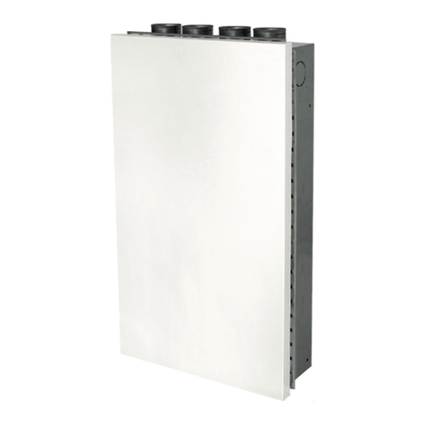
Pichler LG Series User manual

Systematic ventilation.
OPERATING AND
INSTALLATION INSTRUCTIONS
LG 750 – LG 6000
EU-Regulation
1253/2014
for residential buildings
EN13141-7:2010
ErP
2018
Ventilation and
air conditioning /
TÜV-certified design
COMFORT
VENTILATION

USER GENERALSPECIALIST PERSONNEL
OPERATING AND INSTALLATION INSTRUCTIONS LG 750 - LG 6000 PAGE 2
Contents
1. lntroduction Page 4
2. General Page 4
3. Use in compliance with the intended use Page 4
3.1 INTENDED USE PAGE 4
3.2 STIPULATIONS FOR OPERATION WITH FIREPLACES PAGE 5
3.3 STIPULATIONS IN CONNECTION WITH EXTRACTOR HOODS PAGE 6
4. Liability Page 6
5. Warranty Page 6
6. Safety Page 7
6.1 SYMBOLS USED PAGE 7
6.2 SAFETY REGULATIONS PAGE 7
6.3 SETTING UP THE UNIT PAGE 8
6.4 ELECTRICAL CONNECTION WORK PAGE 8
6.5 OPERATION OF THE SYSTEM PAGE 9
U G
7. Customer service Page 10
8. Ventilation unit design Page 10
8.1 DESCRIPTION PAGE 10
8.2 UNIT LAYOUT WITH FITTINGS LG 750 - LG 6000 PAGE 11
9. Control unit Page 12
9.1 HOME SCREEN PAGE 12
9.2 MAIN MENU PAGE 13
10. Messages / Faults Page 17
10.1 ALARM DISPLAY PAGE 17
10.2 OPTIONAL: ALARM LOG IN THE WEB-SERVER PAGE 17
11. Filter maintenance Page 18
11.1 MAINTENANCE INSTRUCTIONS (FILTER) PAGE 18
11.2 FILTER MESSAGE ON THE „PI-HMI“ PAGE 18
11.3 CLEARING FILTER MESSAGES PAGE 19
11.4 FILTER CHANGING PAGE 20
S P - M / I
12. Scope of supply, transport, storage and disposal Page 21
12.1 SCOPE OF SUPPLY PAGE 21
12.2 PACKAGING & TRANSPORT PAGE 21
12.3 STORAGE PAGE 21
12.4 DISPOSAL PAGE 21
13. Technical specifications Page 22

USER GENERALSPECIALIST PERSONNEL
OPERATING AND INSTALLATION INSTRUCTIONS LG 750 - LG 6000 PAGE 3
14. Functioning of the ventilation system Page 22
14.1 FUNCTIONAL OVERVIEW PAGE 22
14.2 SYSTEM DESCRIPTION PAGE 22
14.3 SYSTEM EXTENSIONS FOR HEAT EXCHANGER FROST PROTECTION PAGE 22
14.4 OPTIONAL: SYSTEM EXTENSION FOR AUXILIARY HEATING PAGE 23
14.5 OPTIONAL: SYSTEM EXTENSION FOR COOLING PAGE 26
14.6 HEAT EXCHANGER PAGE 30
14.7 OPTIONAL: DEMAND-DRIVEN PLANT OPERATION PAGE 31
14.8 OPTIONAL: BUILDING AUTOMATION - NETWORKING PAGE 32
15. Übersicht PI-Air-2 Funktionen Page 32
16. lnstallation Page 34
16.1 PREREQUISITES FOR INSTALLATION OF THE UNIT / INTERIOR INSTALLATION PAGE 34
16.2 UNIT INSTALLATION PAGE 35
16.3 LEGEND FOR THE SYMBOLS USED PAGE 36
16.4 SEALING PAGE 36
17. Electrical connection Page 37
17.1 CONNECTION TO WEB SERVER (OPTIONAL!) PAGE 37
17.2 CONNECTING THE OPERATING UNIT PAGE 38
17.3 INSTALLATION ON FLAT SURFACE PAGE 38
17.4 INSTALLATION IN WALL BOX/PANEL FRONT PAGE 38
17.5 MODBUS CONNECTION PAGE 39
17.6 MODBUS RJ12 6P6C PAGE 39
17.7 MODBUS SCREW TERMINALS PAGE 39
17.8 MAINS CONNECTION PAGE 40
18. Shutdown/Maintenance/Cleaning Page 40
18.1 FACTORY CUSTOMER SERVICE PAGE 40
18.2 MAINTENANCE INSTRUCTIONS FOR THE SPECIALISED COMPANY PAGE 41
18.3 MAINTENANCE CHART PAGE 43
S P - C - S
19. Initial starup Page 46
19.1 BASIC PROCEDURE FOR COMMISSIONING BY A SPECIALIST PAGE 46
19.2 CONNECTING AIR DUCTS AND COMPONENTS PAGE 47
20. Installation/Operation from the web server Page 48
21. Spare parts and accessories Page 48
22. Subject to change Page 48

OPERATING AND INSTALLATION INSTRUCTIONS LG 750 - LG 6000 PAGE 4
USER GENERALSPECIALIST PERSONNEL
This chapter contains general
information on the series LG with control
unit type „PI-HMI“.
READ THESE INSTRUCTIONS
CAREFULLY BEFORE INITIAL
STARTUP OF THE UNIT!
This Manual contains notes and
information on safe operation and
proper installation of the Series LG
ventilation unit and on its use and
servicing. Reference this Manual during
servicing to ensure proper execution of
the tasks. Keep this Operating Manual in
a safe place and readily available at all
times.
Fault rectification and intervention
work may only be performed by a
licensed, specialist installation company.
These units are subject to ongoing
improvement and further development.
Your unit may therefore vary slightly
from the description in this Manual.
Subject to change without notice:
This guide was prepared with the
utmost care. Nevertheless, no rights can
be derived from it. We are constantly
making an eort to provide technical
improvements and optimisations to our
products and reserve the right to change
the designs of the units or technical data
completely or in part without any prior
notification.
For the ventilation unit series LG, our
„General Terms and Conditions“ in the
applicable version apply.
Dear Customer,
thank you for purchasing a Series LG
750 - LG 6000 ventilation unit.
Series LG ventilation units are state-
of-the-art. They are convincing by their
high cost eectiveness, ease of use and
reliable operation.
Please read this manual carefully and
follow the instructions to ensure the
safe, reliable and economic operation of
your ventilation system.
Do not use your ventilation system
unless in perfect condition and use only
as designated; be aware of safety issues
and any hazards and familiarise yourself
with the notes and information contained
in this Manual.
Please always keep the model and serial
number (see nameplate on unit) at hand,
in case of queries or when ordering
spare parts.
In case of further questions or lost
documentation, please contact.
1. lntroduction
2. General
J. Pichler
Gesellschaft m .b.H.
9021 KL AGEN F URT
Karlweg 5
T +43 (0)46 3 32769
www.pichlerlu ft.at
Equipment type:
08LG1400R
Construction
year
L
Serial number
Weight
190 kg
Order number
Order No.
Volume flow
max. 1400 m
3
/h
Dimensions WxHxD:
1.445x1.340x765 mm
Voltage / frequency:
230V / 50 Hz
Power consumption
max. 1,0 kW
The energy ecient Series LG 750 to
LG 6000 ventilation units are specially
developed and optimised ventilation
units with integrated Pichler-Air2
controller customised to meet individual
demands.
The ventilation units are deployed for
controlled mechanical aeration and
ventilation with heat recovery from
several dwelling units in multi-storey
residential buildings, student quarters
and old age homes, commercial/hotel/
oce buildings or similar applications.
The purpose of the controlled
mechanical ventilation of living areas
is to improve air quality and to reduce
heating requirements through the
use of a highly ecient heat recovery
system as well as influencing indoor air
humidity.
3. Use in compliance with the intended use
3.1 INTENDED USE
J. Pichler Gesellschaft m.b.H.
9021 KLAGENFURT
Karlweg 5
T +43 (0)463 32769
Onlineshop: https://shop.pichlerluft.at/

OPERATING AND INSTALLATION INSTRUCTIONS LG 750 - LG 6000 PAGE 5
USER GENERALSPECIALIST PERSONNEL
The ventilation unit‘s applications
and designated use are limited to
the deployment and operation for
mechanical ventilation and extraction
of air in residential and non-residential
buildings. The ventilation unit may not
be used for drying, since the unit is
not designed for dehumidifying. The
conveyed air at minimum and maximum
temperatures of -16 °C to + 35 °C resp.
must be free of aggressive vapours and
substances causing wear.
Any other use shall be deemed contrary
to designated use. The manufacturer
shall accept no responsibility for
damages or consequential damages
arising from improper use. Designated
use shall also include compliance with
our prescribed Operating and Installation
Manual.
This unit is available to the general
public and is intended for installation in
residential or industrial buildings. The
unit is used for mechanical aeration and
ventilation of ambient air and, combined
with a heating and cooling battery, also
for re-heating/cooling of the air.
This unit is not intended for use by
persons, including children, with
limited physical, sensory or mental
capacities or lacking experience and/
or knowledge, unless under supervision
or instruction of a person responsible
for their safety. Series LG ventilation
units are not ready-to-use products.
They shall not be started up unless after
proper installation and connection in the
ventilation and air conditioning system.
Only qualified and instructed persons
may work on and with the unit.
Persons transporting or
working on the unit must
have read and understood the
Operating Manual, especially Chapter 6
„Safety“. The end user must be informed
of potential hazards.
Local requirements in terms of stand-
ards, laws and directives, must be taken
into account.
The central air conditioners with heat
recovery should not be installed in
comparably sized rooms, apartments
or facilities with room air dependent
heating apparatus unless:
• safety systems are in place to prevent
simultaneous operation of room air
dependent heating apparatus and units
extracting air, or
• special safety systems will monitor
waste gas extraction of a heating
apparatus dependent on room air. For
ambient air-dependent heating sys-
tems for liquid, gaseous and solid fuels,
the heating or ventilation system must
be switched o in the event the safety
equipment triggers.
Central air conditioning equipment for
controlled ventilation and extraction of
air in an apartment or similar facility
shall not be installed if the facility has
room air dependent heating apparatus
connected to waste gas units with multi-
ple infeeds.
For normal operation of central air con-
ditioning systems, it must be possible to
close any ducts for combustion air
or waste gas systems from heating
apparatus dependent on room air. Shut-
o systems for waste gas from solid
fuel heating apparatus must be manual.
The position of the operating lever must
indicate the status of the shut-o unit.
This is deemed complied with if a shut-
o system is used to block soot (soot
shut-o).
Fire protection requirements
The regional regulatory provisions,
especially the fire protection regula-
tions for air conditioning of buildings, as
amended, must be taken into considera-
tion when installing the air conditioning
system in accordance with the instruc-
tions for fire protection.
3.2 STIPULATIONS FOR OPERATION
WITH FIREPLACES

OPERATING AND INSTALLATION INSTRUCTIONS LG 750 - LG 6000 PAGE 6
USER GENERALSPECIALIST PERSONNEL
Series LG ventilation units were deve-
loped and manufactured for ventilation
in living rooms and rooms with similar
purposes such as oces and seminar
rooms.
For proper operation of the central air
conditioning systems, it must be possi-
ble to close any ducts for combustion
air and flue gas systems of fireplaces
drawing in room air.
Any other use shall be deemed improper
and may cause personal injury or dama-
ge to the ventilation unit, for which the
manufacturer shall accept no liability.
The manufacturer shall accept no liabi-
lity for any damages due to:
• non-observance of the Safety, Opera-
ting and Servicing notes in this Opera-
ting and Installation Manual
• installation of spare parts other than
parts supplied by the manufacturer
• normal wear and tear
On account of the heavy load and irre-
gular operation the extract air of any
kitchen extractor hood present must
not be integrated into the apartment’s
ventilation system. The extract air from
such extractor hoods should be removed
separately out of the roof via an exhaust
air line. The supply air is provided sepa-
rately, e.g. via the window ventilation.
If an extractor hood is being operated
without separate introduction of the
supply air, the air volume balance in the
apartment is no longer balanced and the
proper functioning of the apartment’s
ventilation system is not ensured (odour
entrainment etc.). One possibility is to
operate the extractor hood with adequa-
te air filtering in recirculated air mode.
3.3 STIPULATIONS IN CONNECTION
WITH EXTRACTOR HOODS
4. Liability
5. Warranty
The warranty starts when the unit is put
into operation, or one month after delive-
ry at the latest. You can find details on
the warrantee in our „General terms and
conditions“ in the current version and
the dealer conditions in your country. It
only applies if there is documentation of
maintenance carried out in accordance
with our regulations by a licensed, spe-
cialised installer company.
Warranty claims can be made exclusi-
vely for material and/or construction
flaws that occur during the warranty pe-
riod. In the event of a warranty claim, the
ventilation unit may not be disassembled
without the prior written consent of the
manufacturer.
The manufacturer then only grants
a warranty on spare parts if they are
installed by an installer recognised by
the manufacturer.
The warranty shall expire automatically
at the end of the warranty period, or in
the case of improper operation, such
as operating without filters, installation
of parts not supplied by the manufac-
turer, or where non-approved changes
or modifications have been made to the
system.
Failure to comply with these operating
and installation instructions will auto-
matically void all warranties.

OPERATING AND INSTALLATION INSTRUCTIONS LG 750 - LG 6000 PAGE 7
USER GENERALSPECIALIST PERSONNEL
6. Safety
Read this operating and installation
guide carefully and observe the safety
instructions during installation work,
start-up, maintenance work or general
work on the ventilation unit.
Keep the operating and installation guide
close to the unit during its entire service
life.
Always follow the safety regulations,
warning information, instructions and
comments described in this operating
guide. The specifications mentioned in
this document may not be changed.
Not observing these safety regulations,
warning information, instructions and
comments can lead to bodily harm or
damage to the ventilation unit.
A service agreement is recommended to
ensure that the unit is checked and ser-
viced at regular intervals. Your supplier
can give you the addresses of recognis-
ed installers in your area.
6.1 SYMBOLS USED The following safety symbols identify
text passages in which there are
warnings about dangers and sources of
danger. Please familiarise yourself with
these symbols.
Important information!
Caution! The non-observance of
this warning can lead to injury
or danger to life and limb and/
or damage to the unit.
Caution - dangerous electrical
voltage! The non-observance of
this warning can lead to injury
or danger to life and limb.
The installation, start-up,
maintenance and repair must
be carried out by an authorised
specialist (heating/installation
specialists).
The local national regulations and
standards apply without restriction
beyond these operating installation
instructions in respect of operation of
the unit.
Let the installer of the system instruct
you on the unit and control unit after the
installation. The ventilation unit may only
be used in accordance with the usage in
accordance with the intended purpose
given in Chapter 3 „Use in compliance
with the intended use“, page 4.
All safety and danger notices attached
to the unit and described in these
instructions must be observed.
In the event of any malfunctions, shut
down the unit immediately and secure
it suitably against being switched back
on. Faults on the unit must be rectified
immediately. Make sure that children do
not play with the unit.
After the repair work, the operational
reliability of the unit must be restored by
qualified persons.
Attaching or installing additional
equipment is not permitted. Changes
and modifications to the ventilation
unit are not permitted and release the
manufacturer of any warranty and
liability. Only original spare parts may
be used.
Modifications and adaptations to the
ventilation unit are not permitted and
release the manufacturer from any
warranty and liability.
6.2 SAFETY REGULATIONS

OPERATING AND INSTALLATION INSTRUCTIONS LG 750 - LG 6000 PAGE 8
USER GENERALSPECIALIST PERSONNEL
6.3 SETTING UP THE UNIT The national and local regu-
lations must be observed for
installation and setup. The unit
must be installed only in compliance
with the national installation regulations.
The assembly and installation must be
carried out in accordance with the gene-
ral, locally applicable building, safety and
installation regulations of the respective
municipality, or of the water and electri-
city services and other institutions.
The ventilation unit is designed for
upright installation or in case of ceiling
installation, for the installation on the cei-
ling and may only be set up on a suitable,
load-bearing floor. The unit may not be
subjected to vibrations and the customer
shall provide suitable structural acoustic
decoupling between unit and building.
Permissible reasonable maximum lifting
capacities of persons and lifting equip-
ment must be noted when transporting
the ventilation unit.
Suitable permanent drainage of conden-
sate arising during operation of the ven-
tilation unit will be required, including
eective odour blocking traps (siphon).
Ensure adequate spacing between the
base of the unit and the floor or perhaps
false ceilings.
Installation of the unit, the electrical con-
nection work as well as the installation
and connection work for the water, hea-
ting and condensate connections must
only be performed by a specialist.
Proper installation is essential for ensu-
ring the water-tightness and eective-
ness of the condensate discharge line
and in order to prevent damage to the
building. The condensate drainage has to
be checked for operability by means of
an on-site inspection prior to initial star-
tup and after any servicing work. During
manual transport take care that only
reasonable human lifting and carrying
forces are used.
System components of the ventilation
system such as, for example, air lines
with built-in components, optional
heating batteries with accessories,
which are possibly installed in unheated
areas, must be designed to be suitably
insulated in order to prevent heat loss
or the formation of condensate (if the
temperature drops below the dew point
temperature). If there is a danger of frost
for components, then suitable measu-
res must be taken to ensure automatic,
reliable, frost-free operation.
Structural, safety and fire protection
regulations, provisions and standards
that must be applied locally must be
complied with. If applicable, suitable
measures must be taken during the
installation of the units on site, e.g. the
installation of fire protection dampers in
the air lines, etc.
Take into consideration the ambient
influences and do not install the venti-
lation unit in the vicinity of combustible
liquids or gases, in swimming pools
or in areas subject to the influence of
chemicals.
When installing ceiling units, special
care must be taken to ensure that the
unit is secured at all times and cannot
fall down.
• Warning: dangerous electrical
voltages!
• Failure to observe this risk
can lead to death, injury or
damage to property.
• Before carrying out any work on live
parts, the unit must always be dis-
connected completely from the power
supply (all poles) and secured against
being switched back on.
Electrical connections and work carried
out on electrical components of the unit
and its accessories may only be carried
out by authorised electricians in compli-
ance with the applicable laws, require-
ments, standards and directives.
Before opening the unit and
when carrying out work on the
unit e.g. maintenance work and
repairs, the unit must be isolated from
the mains (all poles disconnected) and
secured against being switched back on
for the duration of the work.
The ventilation units are designed for a
power supply of 230 V/50 Hz or
400 V/50 Hz.
Refrain from any way of wor-
king that has an adverse eect
on safety. For safe operation,
safety equipment must not be disassem-
bled or rendered inoperative.
6.4 ELECTRICAL CONNECTION WORK

OPERATING AND INSTALLATION INSTRUCTIONS LG 750 - LG 6000 PAGE 9
USER GENERALSPECIALIST PERSONNEL
The electrical equipment with the
warning and protective devices of the
unit must be checked regularly to make
sure they work properly. In the event of
malfunctions or deficiencies such as, for
example, loose connections or scorched
cables, the unit must be shut down
immediatel.
Only original fuses with the specified
amperage and dimensions may be used.
If the mains connection of the unit is
damaged or defective, then it must be
repaired without delay in order to avoid
any resulting danger. It is forbidden to
operate the unit until restoration of safe
system operation.
If electrical deficiencies and mal-
functions arise, then only authorised
electricians may determine the cause
and resolve the problem without delay.
After completion of electrical work, all
protective measures on the unit must
be checked (e.g. grounding resistance,
etc.). Details see Chapter 17 „Electrical
connection“, page 50.
It is only permitted to ope-
rate the ventilation unit if all
necessary connections related
to planned external fittings and compo-
nents such as, for example, a pre-heater
battery with air filter, re-heater battery,
sound suppressor, etc. have been estab-
lished properly and are also operational
and in working order.
If faults, deficiencies or damage
occur that can endanger people
or other components, then
the ventilation unit must be shutdown
immediately and all poles disconnec-
ted from the mains power supply. Any
further use of the system must be
eectively prevented until its repair.
Measures must be taken to prevent the
unit from being switched back on unin-
tentionally.
When the front covers are open or
the cover plates removed, make sure
you proceed in a safety and danger
conscious way. With ceiling units, special
attention must be paid to parts that may
potentially fall. Refrain from any way of
working that has an adverse eect on
safety. It is only permitted to operate
the unit with a connected air line and
attached system components such as
a sound suppressor for example, with
a minimum line length of 1000 mm in
order to ensure that the fans, for example,
cannot be touched by the hands.
The ventilation units may only be
operated in accordance with the design
documents. They must comply with the
Equipment and Product Safety Act as
well as the relevant regulations of the
EU guidelines and standards.
Take environmental eects into conside-
ration and do not install the ventilation
unit close to combustible liquids and
gasses, in swimming pools or in areas
that are aected by chemicals or hazar-
dous substances.
Never operate the ventilation unit wit-
hout installed air filters. The air filters
must be checked or replaced regularly
for contamination and damage and clea-
ned or replaced if necessary. The control
unit will warn of the need to replace fil-
ters. Air filters must be replaced at least
every six months or when a correspon-
ding message is displayed on the control
unit. Use only genuine spare filters.
If the unit has not been in service for a
longer time, for hygienic reasons the air
filters have to be replaced before putting
it back into operation.
In case of simultaneous use of the ven-
tilation unit with fireplaces consuming
indoor air, the applicable safety instruc-
tions and standards must be observed.
In the case of indoor air dependent
fireplaces the combustion air supply has
to be provided separately. See the pro-
visions on this topic under the point 3.2
“Provisions for operation with fireplaces”,
page 6.
Owing to their heavy loading and irre-
gular operation, extractor hoods must
not be integrated into the extract air or
exhaust air circuit of the ventilation unit.
Advice on this is provided under point 3.3
„Provisions for use with extractor hoods“,
page 6. Exhaust air extractor hoods must
be operated via separate air lines, with
provision for a suitable fresh air supply,
e.g. by opening windows, or via suitable
air filters in recirculated air mode.
6.5 OPERATION OF THE SYSTEM
OPERATING AND INSTALLATION INSTRUCTIONS LG 750 - LG 6000 PAGE 10
USER GENERALSPECIALIST PERSONNEL
U G
7. Customer service
Please contact the installer of your
ventilation and air conditioning system
or contact us directly for any questions
relating to the compact ventilation unit
of the series LG supplied.
8. Ventilation unit design
The energy ecient Series LG 750 to
LG 6000 ventilation units are specially
developed and optimised ventilati-
on units with integrated Pichler-Air2
controller customised to meet individual
demands.
The ventilation units are deployed for
controlled mechanical aeration and ven-
tilation with heat recovery from several
dwelling units in multi-storey residential
buildings, student quarters and old age
homes, commercial/hotel/oce buil-
dings or similar applications.
Weatherproof variant with flat roof as
standard (unit height + 60 mm).
Suitable bases available on request for
roof-integrated unit design.
20 mm must be added to the unit height
for ceiling units, because of the vibration
damping and hinges provided.
8.1 DESCRIPTION
8.1.1 Unit housing The unit housing is a compact, thermally
insulated galvanised sheet steel frame
construction enclosure with minimal
thermal bridges. The panels are double-
walled, made of galvanised sheet steel
with respectively 30 mm thick insulation
for ceiling unit, 50 mm for interior and
100 mm for exterior installation.
8.1.2 Heat recovery Energy ecient heat recovery is achie-
ved through the adequately dimensi-
oned, highly ecient, corrosion- resis-
tant aluminium air/air counterflow heat
exchanger. Alternatively, enthalpy heat
exchangers which also recover moisture
are available. The integrated 100 % auto-
matic bypass is used to bypass the heat
exchanger (summer use, frost protection
etc.. It is fitted with an internal bypass
for continuous heat transfer control.
8.1.3 Fans The units are fitted with energy-saving
and quiet high performance EC technolo-
gy radial fans. Compared to conventional
drives, the potential for saving energy is
up to 60 %, especially when operating on
partial load. The fans are maintenance-
free.
8.1.4 Outdoor air filters- (ODA-filter)/
Extract air filters (ETA-filter)
The units are supplied with outdoor air
filters of quality standard ODA-filter ISO
ePM1 55% and with extracted air filters
of quality standard ETA-filter ISO ePM10
75%. If there are higher requirements of
the air filter quality, then they can also
be supplied with higher quality stan-
dards. After opening the maintenance
doors, the air filters are easy to replace.
8.1.5 Integrated control and regulation The LG 750 - LG 6000 ventilation units
are equipped with an integrated control
and regulation system as a standard
feature. An operator control unit is
used to operate the unit, which can be
optionally installed directly on the unit.
System operation can be programmed in
accordance with the individual requi-
rements using an integrated daily and
weekly program. The volume flow is set
using a 0 - 10 V control signal, which
can also be used to incorporate external
pressure control systems such as a fan
optimiser, for example.
J. Pichler Gesellschaft m.b.H.
9021 KLAGENFURT
Karlweg 5
T +43 (0)463 32769
Onlineshop: https://shop.pichlerluft.at/

OPERATING AND INSTALLATION INSTRUCTIONS LG 750 - LG 6000 PAGE 11
USER GENERALSPECIALIST PERSONNEL
8.2 UNIT LAYOUT WITH FITTINGS LG 750 AND LG 6000
1 Flexible connection
2 Shut-o valve
3 Outdoor air filter with push-pull device
4 Extract air filter with push-pull device
5 Bypass flap with actuator
6 Counterflow heat exchanger
7 Condensate cup
8 Condensate drainage
9 Exhaust air fan
10 Supply air fan
11 Control uni
Ill.: LG 1000 ...LV for interior installation, illustrati-
on left-hand version, with vertical heat exchanger.
8.1.3 Heat exchanger arrangement The heat exchanger positions shown are
the preferred ones, in each case in left-
hand and right-hand versions for the dif-
ferent inspection sides and with airflow
arrows. Standard ventilation units are
available in the following designs: Ven-
tilation units for indoor installation are
fitted with horizontal heat exchangers;
weather-resistant and roof-integrated
ventilation units are fitted with ver-
tical heat exchangers. Weatherproof
and roof-integrated ventilation units in
version „N“ are designed with a horizon-
tal heat exchanger.Prices and delivery
times for other versions are available on
request.
Standard ventilation units
for indoor installation:
Standard ventilation units with weather-
resistant or roof-integrated design:
WT vertical left WT vertical right WT horizontal leftWT horizontal right
Standard ventilation "N", in weather-resistant
or roof-integrated design:
Type 0810KNDLHVE & 0825NDLHVE:
WT horizontal left
For protection against the counter-cur-
rent heat exchanger freezing in the event
of low outside temperatures, dierent
frost strategies can be taken into con-
sideration, for example by using bypass
control with a re-heater battery. The set
system parameters and also the current
values of temperature, volume flow or
pressure that are currently in operation
can be read on the Pichler handheld ter-
minal or an other operator control unit.
Fault messages are output on the control
panel as a collective fault message or
alternatively as a fault message.
Side-by-side units,
also ceiling units:

OPERATING AND INSTALLATION INSTRUCTIONS LG 750 - LG 6000 PAGE 12
USER GENERALSPECIALIST PERSONNEL
9. Control unit
Product: PI-HMI
Type: 3,5“ touchscreen panel
The settings made on the ventilation unit
are performed via an operator control
unit. Control and operation of the venti-
lation unit is performed via the „PI-HMI“
control unit in-wall or on-wall mounting.
The touchscreen makes performing
settings simple. All important operating
data are displayed.
The control unit is normally
installed in the living area and
should be suitably positioned.
Thermal source areas, radiators, direct
sunlight etc. have to be avoided on ac-
count of their temperature influence!
PI-HMI is a touchscreen panel with
user-friendly graphical user interface
specially developed for controlling venti-
lation systems. The panel communicates
with the PI Air2 system via a Modbus
interface, ensuring easy installation.
The panel communicates with the PI Air2
system via a Modbus interface, ensuring
easy installation.
The following changes to the
ventilation unit can be set from
the PI-HMI control unit. When
the screensaver is enabled, tap the
touch display to open the start view.
9.1 HOME SCREEN Basic functions (such as fan speed,
temperature and configuration) can be
accessed from the start view.
1Time and weekday are shown on the
left in the topmost row on the display.
2The main menu can be accessed from
the icon in the top right.
3The alarm bell in the top left denotes
an active alarm.
4The house icon on the left in the midd-
le row enables an overview screen
for the ventilation unit to be accessed.
Temperatures, air quantities and filter
pressures can be checked.
5The desired temperature value is
shown in the middle row on the right.
Click this value to change it.
6The icons in the lower part of the
start view are for quick access to
the individual components. They can
be changed in the main menu under
Settings – Start view, and so can be
dierent from the figure.
At least one
active alarm
1 2
3
4
5
6
Setpoint

OPERATING AND INSTALLATION INSTRUCTIONS LG 750 - LG 6000 PAGE 13
USER GENERALSPECIALIST PERSONNEL
9.2 MAIN MENU Press this icon to return to the home
screen.
Home screen
Communication
Weekly program
Alarms
Extended operation
Components
Update
Settings
Here you can enter times and modes for
the built-in 7-day clock.
Then you can choose among three die-
rent modes:
• „Whole week“ – A ventilation setting for
the whole week
• „Daily program“ – For each day
dierent ventilation settings can be
parameterized
• „Weekday / weekend“ – Ventilation
settings on weekdays and weekends
are set
By pressing the button, the mode is
turned on or o
1Switching between the dierent modes
2Mode
3Weekday
4Time to start and stop the system
5Fan speed
6Timer: A fan speed can be selected for
a certain period (e.g. in the morning).
Up to four timers can be programmed.
9.2.2 Weekly programm
Daily program
Tuesday
Start Stop
Timer Timer Timer Timer
1
2
3
4
5
6
Static IP/DHCP Static IP
IP address
Net mask
Gateway
Primary DNS
Secondary DNS
Mac address
10.10.10.104
255.255.255.0
10.10.10.1
10.10.10.18
10.10.10.19
00:23:38:00:30:13
Communication Here you can configure LAN settings.9.2.1 Communication

OPERATING AND INSTALLATION INSTRUCTIONS LG 750 - LG 6000 PAGE 14
USER GENERALSPECIALIST PERSONNEL
Alarm log
Alarms
Reset
No. Current alarms
Fire alarm
Alarm external
fire thermostat
External stop activated
Fan lO 1: No
communication
Fan lO 2: No
communication
Alarms
Here you can view active alarms and
an alarm log. In case of an alarm, this
screen can also be accessed via the bell
icon on the home screen.
9.2.3 Alarms
• Air-conditioning:
o General settings:
- Temperature control type
- Desired temperature value
- Minimum Supply air temperature
- Maximum Supply air temperature
o Heat exchanger settings
o Heating register settings
o Cooling register settings
• Ventilation settings: (can also be ac-
cessed from the start screen)
o General settings:
- O: The fans are stopped and the
system is not running.
- Low: Low ventilation level is active.
- Medium: Medium ventilation level
is active.
- High: High ventilation level is active.
- Service stop: The system can only
be restarted locally from the
control unit.
- Week program
- Calendar program:
o Configuration via web server
o Supply air fan settings
o Exhaust air fan settings
• Filter settings:
o General settings
o Outdoor air filter: Reset filter time
o Extract air filter: Reset filter time
Thur
Start
Fri
Stop
Tue Wed Thur 2. Fri
MonSunSatFri
Extended operation
Gen. settings
Fan¬
control Constant pressure
Weekly program
O-Calibration of the
pressure measuring
transducer
(PTH)
O-Calibrate
General settings
Alarm type Dynamic
Measure
O-Calibrate
If a dierent pattern of operation is
required for a short period of time, the
weekly program can be overridden. The
override period can last up to a week
at most. Once the period has elapsed,
the system returns to standard clock-
controlled operation.
9,2.4 Extended operation
9.2.5 Components

OPERATING AND INSTALLATION INSTRUCTIONS LG 750 - LG 6000 PAGE 15
USER GENERALSPECIALIST PERSONNEL
Here you can check if an SD card in-
serted into the PI Air2 Master contains
a new software version. Then select
update in the settings and follow the
instructions on the display
Home screen
Communication
Weekly program
Alarms
Extended operation
Components
Update
Settings
9.2.6 Software update
• Language: The PI-Air2 software sup-
ports the following languages
• Time & Date: Here you can set the time
and date for the system.
• Adjustment: Here you can lock fan
speed during system adjustment.
Once the required air volume has
been reached, the fan is locked at its
current speed. This gives the installer
the opportunity to adjust the system,
ensuring the right amount of air in the
individual rooms without interference
from ventilation system regulation.
• Fire: When the fire alarm is active, this
speed is set for the fans (default = 0%)
Language
Settings
Time & date
Adjustment
Fire
Screensaver
Factory setting
Language
Time
9.2.7 Settings
Fire
Set fan operation in case of fire
alarm
Supply air fan
Exhaust air fan

OPERATING AND INSTALLATION INSTRUCTIONS LG 750 - LG 6000 PAGE 16
USER GENERALSPECIALIST PERSONNEL
• Screen saver: Here you can set the
screen saver timeout period.
• Factory settings: (PIN-requiered) Here
you can restore factory settings.
• Quick access: (PIN-requiered) Configu-
ration of the icons in the lower part of
the start view.
• Software version: Here you can view
information on software versions.
Restore
factory settings?
Ok
Factory setting
Time set before screensaver
starts.
Screensaver
Home screen
Select the data to be displayed
for the home screen
Not visible Visible
Software version number
OJ-Air2-HMI-35T
00:15
Software version number
OJ-Air2 Master
03:34
About the control

OPERATING AND INSTALLATION INSTRUCTIONS LG 750 - LG 6000 PAGE 17
USER GENERALSPECIALIST PERSONNEL
10. Messages / Faults
Pichler Air2 system malfunctions will
be shown as alarms. This display may
dier, depending on the control unit or
internal Web server.
10.1 ALARM DISPLAY
The bell icon flashes on the home
screen.
The operator control unit „PI-HMI“ will
display active alarms and an alarm log
in the ALARM submenu.
In case of an alarm, this screen can
also be accessed via the bell icon on the
home screen.
Pressing the “Reset” button acknow-
ledges all active alarms.
Alarm log
Alarms
Reset
No. Current alarms
Fire alarm
Alarm external
fire thermostat
External stop activated
Fan lO 1: No
communication
Fan lO 2: No
communication
Alarms
At least one
active alarm
10.2 OPTIONAL: ALARM LOG IN THE
WEB-SERVER
The log of the most recent 16 active
alarms is shown in the user menu.
Clicking the “Turn o alarms” button
resets all active alarms
Oper ati on
Ext. operat i on
Temperatur e
Time and date
Control information
Internet
Alarms A larm log Alarm preview Data log Oper ati ng mode
Overview of active and past alarms
Time Date No. Alarm log
Frequency converter alarm extract air fan
Frequency converter alarm supply air fan
Temperature sensor fault: Heat recovery
Pressure sensor defect: High pressure 2. Cooling unit
Pressure sensor defect: Low pressure 2. Cooling unit
Pressure sensor defect: High pressure 1. Cooling unit
Pressure sensor defect: Low pressure 1. Cooling unit
Temperature sensor fault: Heat recovery
Pressure sensor defect: High pressure 2. Cooling unit
Pressure sensor defect: Low pressure 2. Cooling unit
Pressure sensor defect: High pressure 1. Cooling unit
Pressure sensor defect: Low pressure 1. Cooling unit
Temperature sensor fault: PWW heater 1
Frequency converter alarm extract air fan
Frequency converter alarm supply air fan
A alarm B alarm
Alarm/operation/log

OPERATING AND INSTALLATION INSTRUCTIONS LG 750 - LG 6000 PAGE 18
USER GENERALSPECIALIST PERSONNEL
11. Filter maintenance
11.1 MAINTENANCE INSTRUCTIONS
(FILTER)
These instructions relate ex-
clusively to regular inspection,
maintenance and replacement
of air filters by the user.
Check the condition of the air
filters regularly.
If they are very dirty, then the
filters must be replaced imme-
diately. Otherwise the filters
are replaced at intervals of at least half
a year depending of the pollution of the
outdoor air.
Original replacement filters are to be
used exclusively to replace the filters,
taking the designated filter quality stan-
dard into consideration. The ventilation
unit must never be operated without the
air filters for outdoor and extracted air
in place.
If ventilation units are put out
of operation for an extended
period of time, then it is neces-
sary to replace the air filters for hygienic
reasons before the unit is switched back
on.
The ventilation unit will display a filter
replacement warning. An error message
will be displayed on the control unit
when the max. pressure dierence set
for the filter is exceeded.
Plant eciency will drop
and power consumption will
increase unless the filters are
replaced regularly.
11.2 FILTER MESSAGE ON THE
„PI-HMI“
Symbol Designation
Filter ODA ISO ePM1 55%
(outdoor air) standard
Filter ETA ISO ePM10 75%
(extract air) standard
11.2.1 Filter message on touch display
(PI-HMI) Alarms
Alarms Alarm log
Reset
No. Current alarms
Outdoor air filter
Extract air filter
Message on the touch control unit
Compensation
active
Tue

OPERATING AND INSTALLATION INSTRUCTIONS LG 750 - LG 6000 PAGE 19
USER GENERALSPECIALIST PERSONNEL
11.3 CLEARING FILTER MESSAGES After the filters have been replaced, the
message on the touch display (PI-HMI) or
in the web server can be reset by pres-
sing the „Reset“ or „Switch o alarms“
button.
11.2.2 Filter message on the web server
Alarms Alarm log Alarm prediction Data log Status Zones
Displaying and turning off active alarms
Technician
User Maintenance Plant OJ modules
Operation
Extended operation
Temperature
Time & date
Alarm & log
Via the control
Internet
Current alarms
Outdoor air filter
Switch off alarms
A-alarm B alarm
No.
Systematic ventilation

OPERATING AND INSTALLATION INSTRUCTIONS LG 750 - LG 6000 PAGE 20
USER GENERALSPECIALIST PERSONNEL
When replacing the air filters,
avoid soiling the unit and its
components. Dirty air filters
must be immediately and suitably dispo-
sed of. It is advisable to package the air
filters in an airtight container immedia-
tely after removal to avoid contaminati-
on of the ventilation system and the unit.
Before carrying out any work
on live parts, the unit must
always be disconnected com-
pletely from the power supply (all poles)
and secured against being switched
back on!
Before pulling the air filters (2) out of the
unit, the filter‘s clamping frame (1) must
be released by pulling it forward. Only
then can the air filters (2) be pulled out
easily and replaced.
Caution with ceiling units:
Care should be taken when
opening the housing or loosen-
ing component fixtures as the loosened
components may potentially fall!
When inserting a new filter (2),
make sure there is a good seal
and adequate clamping bet-
ween the air filter and filter clamping (1)
frame in order to avoid too much filter
bypass leakage.
Note the indication of proper air flow
direction on the filter.
Where can I order filters?
Use only original replacement filters of
the filter class specified.
11.4 FILTER CHANGING
J. Pichler Gesellschaft m.b.H.
9021 KLAGENFURT
Karlweg 5
T +43 (0)463 32769
Onlineshop: https://shop.pichlerluft.at/
clamping frame (1)
FIlter ETA ISO ePM10 75% (2)
Filter ODA ISO ePM1 55% (2)
This manual suits for next models
2
Table of contents
Other Pichler Fan manuals

Pichler
Pichler LG 500 System VENTECH User manual

Pichler
Pichler LG 100 UP Specification sheet

Pichler
Pichler LG 750 User manual

Pichler
Pichler PKOM4 Classic Specification sheet

Pichler
Pichler LG 100 DE Specification sheet

Pichler
Pichler LG 500 System VENTECH User manual

Pichler
Pichler LG 350 User manual

Pichler
Pichler LG 500 P-R User manual

Pichler
Pichler LG 740 Specification sheet

Pichler
Pichler LBE 250AO Specification sheet